LS-THC Comprehensive Troubleshooting Guide
6/11/2021: We have created a THC Troubleshooting Flow chart that should greatly increase your ability to fix any THC related issues. We highly recommend first working to this chart to help solve any issues that you might have!
THC TROUBLESHOOTING FLOW CHART REV. B
**********The below guide has been Archived. Please refer to the troubleshooting Flow Chart above for more recent help on troubleshooting your THC system. ***************
Purpose:
The purpose of this guide is to ensure that your plasma cutter/THC wiring are correct and also that all of your components are functioning properly. There is a separate guide for both of the input methods; Divided Voltage and Raw Voltage. You will need a digital multimeter (DMM) that is capable of measuring DC Voltage and continuity in order to perform the below troubleshooting steps. IF AFTER CHECKING THIS GUIDE YOU CONFIRM THAT YOU ARE WIRED UP CORRECTLY BUT YOUR VOLTAGE READINGS IN FIRECONTROL ARE LOWER THAN EXPECTED (10-30V RANGE), TRY UNPLUGGING YOUR LAPTOP CHARGER FIRST. IF THE ISSUE PERSISTS, CHECK FOR GROUNDING ISSUES HERE.
DIVIDED VOLTAGE INPUT
A1. Verify that your plasma cutter’s 50:1 voltage divider port is functioning properly while cutting.
If your plasma cutter is equipped with a 50:1 voltage divider in the CNC port (called a CPC port on Hypertherm), we will use your DMM to measure the DC Voltage across the two pins of this port while the plasma cutter is cutting. Place the black electrode of the DMM on the negative pin (torch) of your voltage divider port, and place the red electrode on the positive pin (work clamp). Next, perform a straight line cut with your machine with the THC panel toggled off in FireControl and measure the DC voltage across these two pins. Depending on your plasma cutter, the typical arc voltage while cutting will range between 60-150V and since the voltage divider is 50:1, you should see an output voltage of around 1.2 - 3V. If your voltage value is within range but is a negative reading, you have your two pins switched (positive and negative are reversed). If you are not getting the expected voltage here, contact your plasma cutter manufacturer to remedy the issue. NOTE: The Divided Voltage cable from your plasma cutter to the VIM box DIV INPUT socket is for monitoring voltage only NOT for Torch Firing. You will still need to setup remote torch firing separate from voltage monitoring; once connected this torch firing cable plugs into the Torch On/Off port on the electronics enclosure.

A2. Verify that your Divided Voltage Input Pigtail Cable is wired correctly
Next, you will need to use the provided ‘Divided Voltage Input Pigtail Cable’ for wiring up to the divided voltage port that you tested in step 1. Per the instructions, the red wire should be connected to the negative pin, and the black wire should be connected to the positive pin (see pic below). NOTE: Yes we know this is reversed from a color perspective but please make sure that you are wiring this cable correctly according to the picture below or you will get no voltage reading!

Once you’ve fashioned a suitable plug onto this bare-wire end for connecting to your voltage divider port, use your DMM to verify that your wiring is correct. Touch the red electrode of the DMM to the inside of the barrel connector and the black electrode to the outside of the barrel connector. The DC voltage that you measure here should be identical to the value measured in step 1. If you are getting a negative voltage here but the magnitude of this value is correct, you need to switch the polarity of your wiring on the plug to the 50:1 voltage port. Failure to do so will result in no voltage reading in FireControl; the THC module can only measure positive voltage not negative.
A3. Verify that your VIM Box is wired and operating properly
Plug the barrel jack end of your Divided Voltage Input Pigtail Cable into the DIV INPUT socket on the VIM Box. Next, plug in the supplied Output Voltage Cable into the DIV OUTPUT socket on the VIM Box.
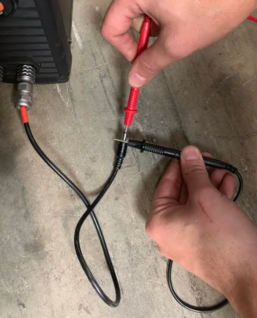
Next, locate the free end of the Output Voltage Cable and note the pins labeled 1 and 2. Using the DMM, touch the Red DMM lead to pin 1 and the black lead to pin 2. Perform the same straight line cut as before and measure the DC voltage between these two pins as shown in the pictures below. For safety, do not touch the exposed leads of your DMM when performing this test.Again, this voltage value should be positive!
You will notice that the DC voltage that is coming out of the VIM will be less than what you measured in steps 1 and 2. This is because the VIM further divides the voltage for an effective voltage division of 73:1. To figure out the ballpark voltage that you should be getting, multiply the voltage you found in steps 1 and 2 by 0.685 to get the value you should expect in step 3. For example in step 1 we measured 2.16V multiplied by 0.685 gives us an expected voltage of 1.47V which is very close to the 1.45V we measured.
If you are getting good voltage values in steps 1 and 2 but measure no voltage or an unexpected voltage coming out of the VIM box, double check the continuity in the Output Voltage Cable. If everything looks good with the cable, you are more than likely experiencing a VIM module failure; contact support@langmuirsystems.com for next steps.
If you are getting the expected voltage values (and voltage polarity) in steps 1, 2, & 3 but still showing no voltage in FireControl, proceed to the section ‘Further THC Module Troubleshooting’ below for further help.


RAW VOLTAGE INPUT
!STOP! VOLTAGES HAZARDOUS TO HEALTH AND LIFE ARE PRESENT INSIDE A PLASMA CUTTER CHASSIS.
Connection to the main terminals of your plasma cutter either inside or outside of the chassis can expose you to deadly voltages. Our LS-THC operating manual should be read in its entirety before attempting to install this hardware. If you are unqualified to perform the installation and subsequent testing, we recommend working with a qualified professional electrician to perform this installation. Langmuir Systems will not be held liable for damage or bodily harm as a result of improper installation.
Making modifications to your plasma cutter in order to connect to the main plasma terminals may or may not violate your plasma cutter’s warranty. Langmuir Systems does not provide instructions for hooking up to the main terminals of your plasma cutter. It is your responsibility to check with your plasma cutter manufacturer regarding the terms of the warranty and whether or not executing the wiring procedure violates those terms. Langmuir Systems will not be held responsible for warranty violations.
Once the Raw Voltage Pigtail Cables are connected to your Plasma Cutter, they are live and carrying high voltages. The sheathed banana connectors protect against exposure to high voltages ONLY when installed into the VIM module. YOU WILL BE ASKED IN THE BELOW GUIDE TO MEASURE DC VOLTAGE BETWEEN THESE UNINSTALLED BANANA CONNECTORS TO VERIFY INSTALLATION; BE CERTAIN TO NEVER TOUCH THESE EXPOSED LEADS WHEN THE PLASMA CUTTER IS UNDER OPERATION OR YOU RISK EXPOSURE TO HIGH VOLTAGES THAT CAN KILL YOU.
Completing the wiring procedure may require you to open up the cabinet of your plasma cutter power supply which will expose you to high powered electrical components. It is your responsibility to make sure that all work is done safely and with the power disconnected and discharged. If you have any doubts regarding your ability to safely perform this work, we strongly urge you to solicit the services of a professional electrician. Langmuir Systems will not be held responsible for any injury or death resulting from the incorrect or unsafe execution of this procedure.
B1. Verify that your Raw Voltage Pigtail Cables are connected correctly
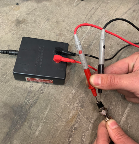
In this step we need to verify that you have successfully connected to raw voltage inside your plasma cutter and that the polarity of this wiring is correct. Using a DMM, connect your black DMM lead to the black raw voltage banana connector and connect your red DMM lead to the red raw voltage banana connector (as shown below). DO NOT TOUCH THESE EXPOSED BANANA CONNECTORS OR DMM LEADS WHILE CUTTING! Next, perform a straight line cut with your machine with the THC panel toggled off in FireControl and measure the DC voltage across these two connectors. Depending on your plasma cutter, the typical arc voltage while cutting will range between 60-150V. If you are getting a negative voltage reading, you need to switch the connection points inside your plasma cutter or FireControl will read 0V (FireControl can only read a positive voltage). If you are getting no voltage reading at all, you will need to contact your plasma cutter manufacturer for better guidance on how to hook-up to raw voltage inside your cutter.

B2. Verify that your VIM Box is wired and operating properly
Plug the banana connector ends of the Raw Voltage Pigtail Cables into the corresponding sockets on the top of the VIM box… Next, plug in the supplied Output Voltage Cable into the PV OUTPUT socket on the VIM box.
Next, locate the free end of the Output Voltage Cable and note the pins labeled 1 and 2. Using the DMM, touch the Red DMM lead to pin 1 and the black lead to pin 2. Perform the same straight line cut as before and measure the DC voltage between these two pins as shown in the pictures below. For safety, do not touch the exposed leads of your DMM when performing this test. Again, this voltage value should be positive!
You will notice that the DC voltage that is coming out of the VIM will be much less than what you measured in step 1. This is because the VIM divides the raw voltage input for an effective voltage division of 73:1. To figure out the ballpark voltage that you should be getting, divide the voltage you found in step 1 by 73. For example in step 1 if you measured 110V, divide this by 73 and you should expect roughly 1.5V DC across the plug pins.
If you are getting a good voltage value in step 1 but measure no voltage or an unexpected voltage from the VIM box, double check the continuity in the Output Voltage Cable. If everything looks good with the cable, you are more than likely experiencing a VIM module failure; contact support@langmuirsystems.com for next steps.
If you are getting the expected voltage values (and voltage polarity) in steps 1 & 2 but still showing no voltage in FireControl, proceed to the section below for further troubleshooting.
FURTHER THC MODULE TROUBLESHOOTING:
!WARNING! DANGEROUS HIGH VOLTAGE PRESENT INSIDE ELECTRONICS ENCLOSURE: In order to troubleshoot the THC module, the electronics enclosure cover needs to be removed. Make certain to completely disconnect the power cord from the power inlet rocker socket on the front of the electronics enclosure before proceeding. If you need to cut with the machine while the cover is off, be certain to never touch any high voltage input leads including behind the rocker inlet switch and the wires plugged into the power supply.
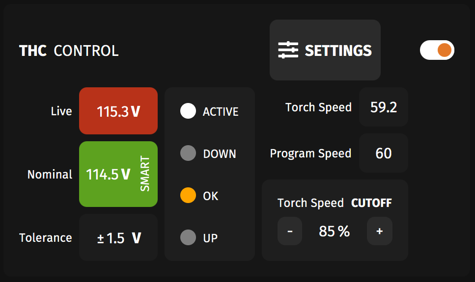
C1. Verify that your THC unit is connected and functioning properly in FireControl
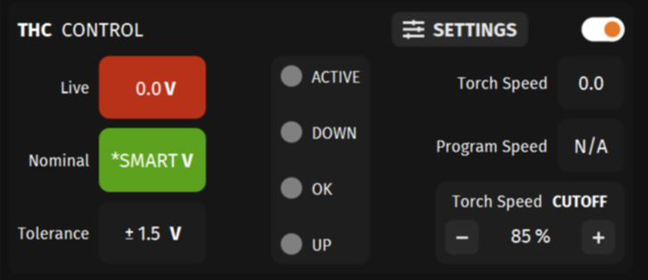
Open FireControl and make sure that your THC is properly connected to your computer. If connected, the THC panel should open on the left side of FireControl. To test that your THC module is working properly, jog the machine around and watch the Torch Speed value in the THC control panel. This value should change as you jog the machine around. If you are getting no speed to show here, your THC unit is likely defective or installed into the socket wrong; please contact support@langmuirsystems.com for a replacement unit.
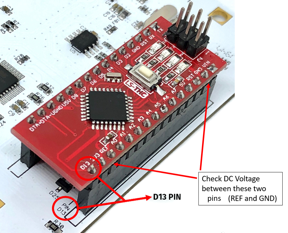
C2. Verify that reference voltage to the LS-THC is correct
With the THC plugged into the white motion control board and the CNC electronics box plugged into your computer, you should see LEDs illuminate on both boards. Next using your DMM, check DC voltage between the REF pin and the GND pin on the THC unit. You should be measuring something around 4.0 - 4.2V here. If you are getting no voltage here, please contact support@langmuirsystems.com as your THC unit could be damaged.
C3. Verify that the LS-THC resting voltage is correct.
With the THC plugged into the white motion control board and the CNC electronics box plugged into your computer, you should see LEDs illuminate on both boards. Make sure that your VIM box is hooked up to your plasma cutter and that the VIM box is hooked up to the THC port on the front of the electronics enclosure. Next using your DMM, check DC voltage between the A1 pin and the GND pin on the THC unit. You should be measuring close to 0V here. If you are measuring 0V here but FireControl is showing 300V, your THC unit is damaged and needs to be replaced. Also,if you are getting a voltage reading here that is greater than 100mV while the plasma cutter is off, please contact support@langmuirsystems.com as your motion control board could be malfunctioning.

C4. Verify that the LS-THC cutting voltage is correct at the THC unit
With the THC plugged into the white motion control board and the CNC electronics box plugged into your computer, you should see LEDs illuminate on both boards. Make sure that your VIM box is hooked up to your plasma cutter and that the VIM box is hooked up to the THC port on the front of the electronics enclosure.
Next, you will need to perform a straight line cut with your machine with the THC panel toggled off in FireControl. While cutting and using your DMM, check DC voltage between the A1 pin and the GND pin on the THC unit (make sure that your black DMM lead is connected to GND and the red connected to A1). The DC voltage that you measure across these two pins should match the same voltage that you measured in step 3 of the Divided Voltage input guide or step 2 of the Raw Voltage input guide above. If you are getting no voltage reading here but measured a voltage out of your VIM box in the previous troubleshooting steps, then you most likely have a continuity issue between your VIM box and the Motion Control Board. Put your Voltmeter in Continuity mode and trace the two THC wires that are plugged into your white Motion Control Board back to the VIM box (Look for the gray and white wires that plug into DIV and GND on the Motion Control Board and make sure that these both have continuity to the DC barrel connector that plugs into the output side of the VIM box).
If you are getting DC voltage between these two pins while cutting but the voltage is much less than what was found in step A3, it is possible that you have a grounding issue between your electronics box and the machine frame. Please check out our following guide as you most likely have a DC grounding issue: http://www.langmuirsystems.com/thc/guide#grounding-section
We also recommend trying to re-run this test with your laptop charger unplugged to see if this fixes the issue. Another potentional fix of a grounding issue is to remove your electronics box from the leg completely and retry the cutting test. If this fixes your issue, please contact support@langmuirsystems.com for plastic isolating spacers.
C5. Unplug your Laptop Charger
We have found that some customers are getting lower than expected Live Voltages in FireControl when their laptop charger is plugged in due to a grounding issue in the supply voltage. If you are experiencing this issue, we recommend unplugging your laptop charger and trying to cut again and seeing if it fixes the issue. Otherwise, you may have another lingering grounding issue and we suggest troubleshooting here: http://www.langmuirsystems.com/thc/guide#grounding-section