Torch Not Firing – Troubleshooting Guide
1.) Confirm that Mach3 Settings are correct:
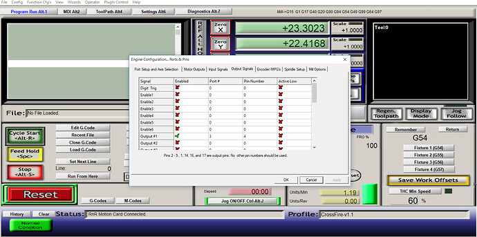
a.) At the top bar click Config > Ports and Pins and then click the tab for Output Signals. Your screen should look identical to the screenshot below with Output #1 checked green and Port# = 3 and Pin Number = 4. No other outputs should be enabled. If your configuration is different, make the correct changes and click apply and then OK.
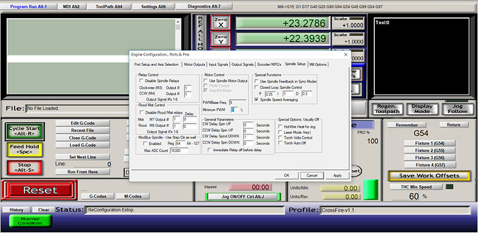
b.) Go back into Config > Ports and Pins and select the tab ‘Spindle Setup’. Your settings should be identical to the screen below with the box for ‘Disable Spindle Relays’ unchecked and Output #1 entered for both Clockwise and CCW directions. If your configuration is different, make the correct changes and click apply and then OK.
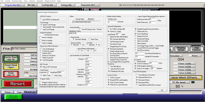
c.) Go into Config > General Config and confirm that all of your settings are identical to the ones shown below. If they are not make the correct changes and click OK.
d.) If your settings are correct, turn your plasma cutter on and place the torch into the CrossFire torch mount. Be sure that nothing is below the torch and you are over air between two slats. In Mach3 there is a button ‘Torch On/OFF F5’ which is a toggle button to manually fire the torch. Click this button once and you should see your torch pilot arc come on. You should also see the ‘Torch On/OFF F5’ button blinking yellow. If your torch fires and the pilot arc goes out, be sure to press ‘Torch On/OFF F5’ again so that the light stops blinking and the plasma cutter stops flowing air. If your torch is still not firing, proceed to step 2.
2.) Check Plasma Cutter Wiring:
a.) We are going to check that splicing into the plasma cutter wiring was done correctly. Unplug the black barrel connector for torch firing from the electronics enclosure. Make sure your torch is in the torch mount and is over air between two slats and turn your plasma cutter on. We are going to simulate the relay firing the plasma torch by jumping the two leads on the barrel connector. To do this, we recommend using a paperclip and placing on end inside the barrel connector and touching the other end to the outside of the barrel connector. If torch wiring was done correctly, this will cause the plasma cutter to fire when the connection is jumped across the barrel connector. If your torch is still not firing, proceed to step 3.
3.) Check Relay and Breakout Board:
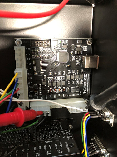
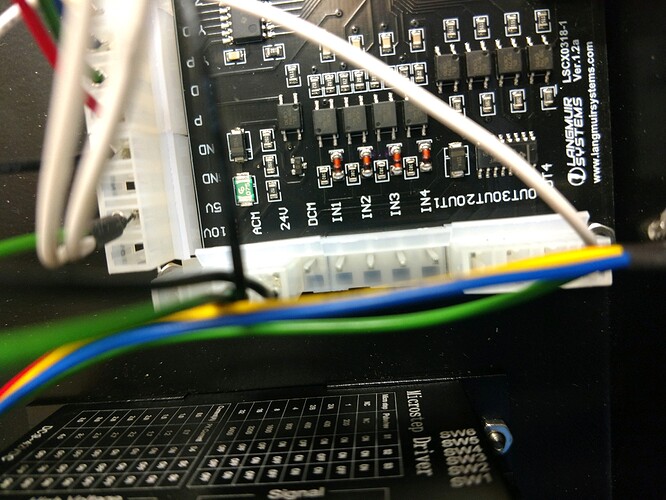
a.) With all cables unplugged from the electronics enclosure, remove the front panel by unscrewing the 10 sheet metal screws from the top and bottom of the front panel. Plug the USB cable into the enclosure and open Mach3. You should see an LED (either red or green) on the Langmuir Systems electronics board and it should be blinking when USB is plugged into the computer. Press the blinking Reset button in Mach3 and the board LED should go from blinking to solid to indicate that it is connected.
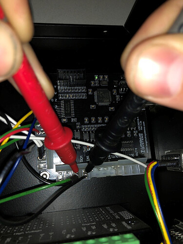
b.) For the next steps you will need to have access to a multi-meter for checking continuity and voltage. Switch your multi-meter to measure voltage in the 5V range. With the black probe on the DCM connector and the red probe on the 24V connector you should be measuring between 4-5V (be sure USB is plugged in and Mach3 is on). If you are not getting the correct voltage, then you will need to have the Main Wiring Harness replaced.
c.) Next, place the red probe on 24V and the black probe on Out4. You should be measuring 0V. Make sure that your Torch Firing Cable is not plugged into the enclosure. In Mach3, click the ‘Torch On/OFF F5’ button and the light should be blinking yellow. Go back to the enclosure and place the red probe on 24V and the black probe on Out4. You should be measuring between 4-5V. If you are not getting the correct voltage, you will need the Langmuir Systems Break-out board replaced. Be sure to click the ‘Torch On/OFF F5’ button again before plugging your torch back in to disarm the manual torch firing (button should not be blinking).
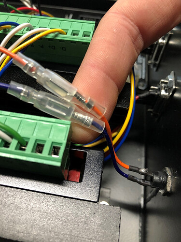
d.) Inspect the blade connectors (orange and purple wires) in the clear plastic sheathing and make sure that they are plugged in correctly. Also inspect the backside of the torch inlet port and be sure that the connections are soldered on securely.
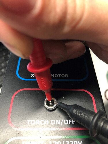
e.) With your multi-meter in continuity mode, place one probe on the outside of the female barrel connector and one probe on the pin inside the barrel connector at the Torch On/Off Port. In Mach3, click the ‘Torch On/OFF F5’. You should have continuity between these two pins when the yellow Torch light is blinking in Mach3. If you don’t have continuity, you will need your Main Wiring Harness replaced due to a faulty relay. Be sure to click the ‘Torch On/OFF F5’ button again before plugging your torch back in to disarm the manual torch firing (button should not be blinking).
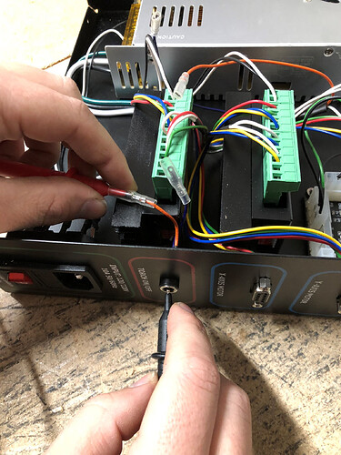
f.) Next we are going to check for continuity through the torch inlet female barrel connector on the electronics enclosure. Unplug the orange and purple blade connectors from the main wiring harness. With your multi-meter in continuity mode, place one probe on the orange blade connector and touch the other probe to either the outside barrel or the inside pin. You should have continuity to one of these. Next, probe the purple blade connector and probe the barrel connector again (if the orange had continuity to the inside pin, then probe the outside of the barrel connector and vice versa). If you are not getting continuity through both of these blade connectors to the port, you will need to have your inlet port replaced.
If you need to replace faulty items, please contact us at Support | Langmuir Systems and we will get you taken care of!
