I’m struggling with lead in room on letters, I’m not sure how to fix the errors. I have tried using bold letters and also scaling the whole project up to make the letters bigger. I was going to try narrowing the kerf width, but for the life of me I can’t figure it out. I swear I knew how to do it last week. But with frustration comes stupidity.
Can someone give me some pointers?
text test file.dxf (34.5 KB)
It’s just a little small but to cut the inside of the A and R use a 0.055 lead in and pierce clearance and it will make a cut path.
1 Like
Thanks, Is it possible to get a clean line without the lead in if I wanted to cut even smaller letters?
If you can nail your pierce delay which is tough without getting some sort or divot by setting sideways compensation to center and 0 lead in and 0 pierce clearance.
Not saying it cant be done but it will be tough cause all the heat will be concentrated in such a small area. Some letter will be fine but some will give you a hard time.
How small of letters do you want those are only 1/2"
1 Like
I’m not sure. This is part of an aluminum “hood ornament” I’m working on for my RV.
Lets just say I should have started with a less complex idea. This one has taken a long time but taught me how to fix many mistakes.  I could always up size it, but I don’t want a hub cap sized emblem.
CALVIN ON A LOG TAKE2.dxf (129.4 KB)
This started as a color page from one of my books.
I’m a learning by doing kind of guy and the documentation on all of this is pretty terrible IMO. But, I’m pretty happy with the current results.
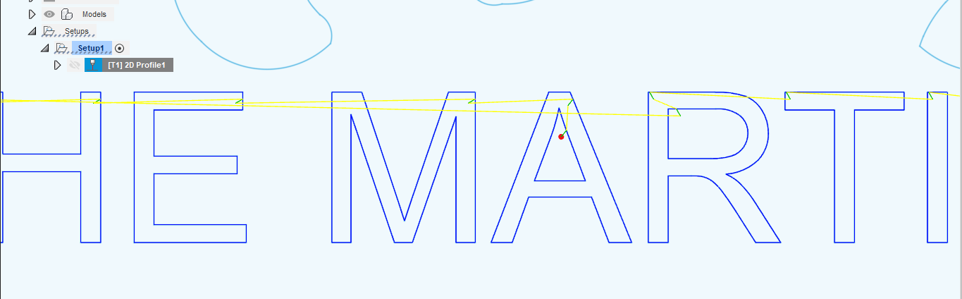
when i zoom in close there is no cut path to part of the letters? did I do something wrong to caused this?
You wont be able to cut those from inside.
If you set your sideways compensation to center with a 0.05 lead in it will lead in from the the inside of the letter and cut right on the line.
Not sure what your plan is but if your just cutting out the letters and the characters your going to lose the inside of the A and R without a bridge.
Actually you can increase your lead in to 0.08 with sideways compensation set to center
1 Like
What is sideways compensation? I haven’t found that setting yet.
By sideways compensation, did you mean no offset? when I try no offset it moves all of the lead ins to the outside.
I reversed the cut side at every starting point and it seems to be error free. Of course now I’m over the line limit on Sheetcam. 
Is there a better way to have done it?
Thanks for all of your help. It’s pushing me to figure things out more.
I assumed you were using fusion because thats where most people run into issues with things like this.
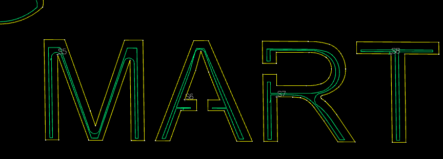
Here’s a screenshot of your file in sheetcam.
Here’s a screen shot with that M and R fixed.

And here’s the fixed file that will work with sheetcam or fusion.
martins.dxf (95.8 KB)
What is sheetcams line limit without purchase? The file is only 800 lines.
I believe the sheetcam limit is 800 lines. What did you do to fix the M and the R? I tried moving the start points around but couldn’t get a toolpath to cut the whole letter?
Last night I ran the operation with “no offset” selected, but it turned all of my lead ins to the wrong side. I manually had to change each one back to the correct side.It did however give me a complete operation with no errors, so that’s good. I was thinking there has to be a better way.  Thanks for all of your help.
I just opened the file in fusion and made the leg of the M the same width as the other side that it would cut and the R just got rid of that sharp turn in the leg.
1 Like
Awesome. I’ll try to go back to my original file and do the same. As a side note, If I add the text in sheetcam will it automatically use fonts that it can cut?
I’m not sure how it works I don’t use sheetcam very often and haven’t used any of its features beside making cut paths.
Is there a way to bridge the letters in sheet cam? I’m striking out with sheet cam and inkscape when I try to modify the letters. Is there something procedurally that needs done first?
Have you converted the text to paths? You need to do that first. Then select a letter (they should all be just vector shapes now) - if your selection has multiple letters, check the status on the bottom of your screen - it probably says “group of x objects” or something similar. Ungroup until you’re down to just single letter shaped objects. Now you can select the path and cut the lines, add nodes, add new lines, etc to create your bridge. But the key is to first convert the text to paths.
1 Like
You will probably have issues trying to get those small letters to bridge. In the A you only have a .125 line to try and make the letter readable and have a bridge.
You could try to cut that but I don’t know how it would turn out.
m.dxf (101.0 KB)
OK, I’ll try that when I get home tonight. I fought with it last night for way too long and got nowhere.