Sometimes I am so confused, I can't even figure out how to ask a question

So there I am needing some holes in some 1/4" mild steel for a project I am working on for my hoist.

I bought the metal, “pre-Langmuir”, and I wanted to use it.

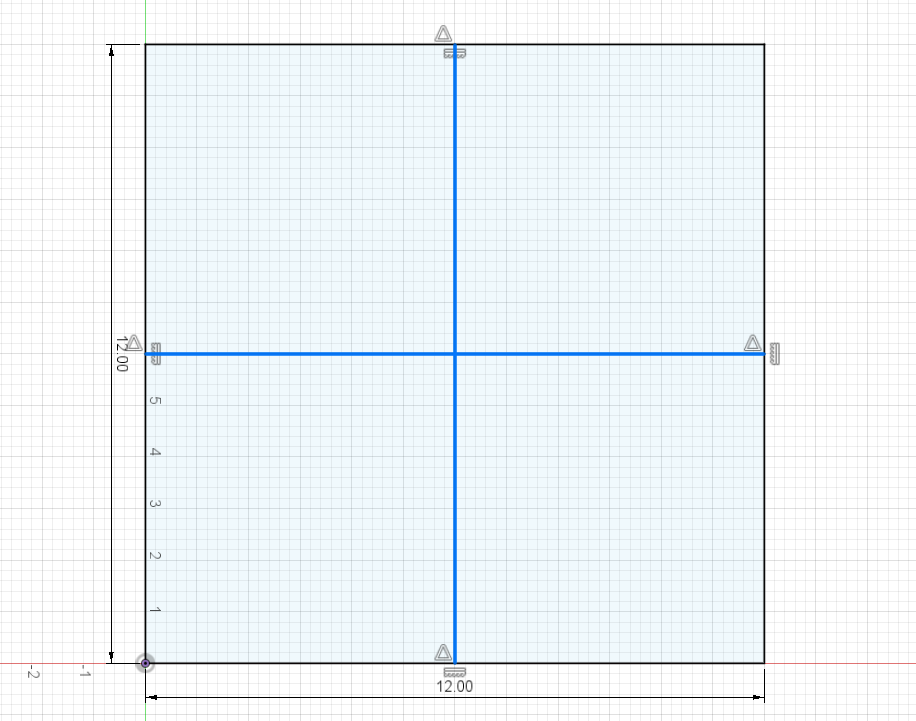
I needed 5 holes in each plate, and all 3 plates should be the same. One “big hole” (1.5 dia) in the center, and 4 (3/8 dia) holes at the mid point of each side of the square.

Well I draw it out in 360 and run into all kinds of problems, mostly having to do with, for some reason, not being able to turn a “cut line” into a “construction line”.

Well after some “jacking about” I finally get what I thought was a “construction line square” with the 5 holes" in place.

So now how the hell do I “place the metal properly” so that the holes end up in the right spot?

Well my dumb ass decides to ‘dry run" the program, then shift it around, then "rinse and repeat’ until I get it “good nuf”

Hit dry run, and “reposition it”

Again hit “dry run” and reposition it.

Then I was “ok with it” and hit “run” and to my dismay, I FORGOT TO HOOK UP THE DAMN GROUND CLAMP!!!

Well the cuts were of course all “jacked up” but I was able to stop it relatively quickly’

So I take my “Mulligan” and hook up the ground.

I have no idea where the hell that little “divot” came from, but it’s not a big deal in this project, so I call it a “win”

Now here is the hard/interesting part. I have 2 more plates that need the same holes.

I can not figure out for the life of me how to do this, so i go “old school” and just use ‘witness marks’ on the plates and the table.

Well it aint 'NASA Accurate" but its ok, I guess.

Any suggestions on what to do in a situation like this next time?

I just did something similar with bar stock. I left the outside cut line and just stopped the program after the holes were cut.

It didn’t require a high degree of precision, so I just lined up the torch with the lower left corner of the bar stock.

I did have an issue with Firecontrol including the perimeter lead in with the size of the drawing. I found that I had to move my work zero over by the distance of the lead in.

I could have rotated the part, so the lead in was not on the left or bottom side. I could also have set the origin to the center and made a center mark on the work piece to zero the torch.

2 Likes

I just read David’s response and realized that I set out to do this like you were cutting out the entire piece including the outside. I have done exactly like David mentioned with projects in the past. All it takes to stop the program is to hit the space bar on the computer after the holes are cut.

It is nice to have a straight edge or square so you can position each piece of metal in the exact same spot. You could even use a square cut out of plywood and clamp it to the table. This way you only need to get the first one lined up appropriately. Each time before starting the cut, remember to tell the torch to “Go To Work Zero.”

(So in light of the fact that I read every third word, you might get some value out of what I did here. For your exercise, you could change the outer square to construction lines in the same way that I explain below.)
Not sure where you want me to start but lets just do a mock up. I first make a 12 x 12 square. Then I place two lines at the midpoint and cross in the center. All of the holes will live somewhere on those lines:

I want the center lines to be construction so I select one, then hold [CTRL] and select the other:

Both lines are selected so I hit “x”. The “x” will switch the line from construction to/from regular:

Now I make the center hole 1.5 inches, easy enough. For the 3/8" holes I will make one hole in the top and then make a “circular pattern” of 4 to make the other 3.

Extrude the body and then go to Manufacturing in Fusion 360 or just use the sketch for SheetCAM.

Once you get to the table, import your gcode file and set whatever will be your program origin.
Now put the torch on table that will correspond to the location on the metal in which you want the corner of the sketch to be represented.

That’s it.

1 Like

^^^What they said^^^

I always try to use a corner, and if the area is tight, or it’s an odd shape, then I will get dimensions from F360 so I know that my 0,0 origin will be xx.xxx" from the first hole on X and xx.xxx" on Y.

Once you upload in to FC, you can zero out your axis and then drive around to verify that all of your cut points will be within your designated boundaries.

1 Like

This sounds way overly complicated for something so simple.

Create a sort of jig or stand-off and place your metal.

Run program.

Replace cut sheet with a new sheet and use the same jig or stand-off and run the program on the new sheet.

Rinse and repeat.

I have an “L” I made that I use with one of my many squares from my welding table, but it also helps to set an edge on my table when I need it.

I even posted abour using a Fireball square as it sets you at the exact distance needed for full use of the 48" cut envelope.

Maybe I’m not understanding something but this is way too simple.

3 Likes

Much like the others have said - aligning your blank to a “similar” location will do wonders.

I have to ask, based on some earlier posts, are you changing the origin in Fusion to the lower left corner when in Manufacturing? If not, it makes loading repeat jobs so much easier. (Just go to “Home - Work 0”, ensure the new plate is just below / left of the nozzle, and cut. Run a Dry Run if needed to ensure plate is in correct location.)

2 Likes

Thanks guys.

I basically did like Jim did in his above post, (although he explained it much better than I did)

So, I recon I was not too far off.

I don’t know how often this comes up, but is there some sort of “pointy tipped doo-hicky” that is made that can be quickly swapped out on the torch in order to help “locate the tip center” ?

Or do people just make them out of “old tips”?

In this case, I switched the origin to be in the center. Basically because that was the easiest for me to locate on my blank.

The hard part was, “aligning” it so that the 4 “outer holes” were being properly cut.

A pointy tip like that could be 3d printed and put in place of the nozzle for locating the exact center of the torch. I may work on that later today for Hypertherm nozzles.

2 Likes

Here’s a link to another thread here about the 3d printed pointy things that fit on to your torch. This lets you easily line up corners, or existing holes for indexing or just adding new features to parts.
If you don’t have a 3d printer and would like a pointy thingy. Drop me a dm we can work something out, I have some “extras” from a batch I made before. I know they work on the PT-60 sized torches if the bore size and threads are the same on the hypertherm they may work on it as well.(I checked some drawings these will not work on the hypertherm (1" bore) IPT-60 is 3/4")

1 Like

Been there done that, don’t forget to take it off before you hit the “Go” button. Ask me how I know.

85psi behind it makes quite a projectile.

3 Likes

Here is my 3d printed pointer for the Hypertherm torch. It should fit any torch that uses Hypertherm consumables. It is designed to screw on in place of the shield, so the nozzle and electrode stay in place. I made it Orange to help prevent me from hitting start with it still on the torch. I’ll put it on Thingiverse and probably Makerspace.

Link to Thingiverse file Hypertherm plasma torch pointer by starrcycles - Thingiverse

5 Likes
2 Likes

This look great!

I have a Razorweld machine though.

My SIL just got a 3D printer for his B-day and is “chomping at the bit” to make things.

If anyone has a file that they are willing to share that will work for his printer I would really appreciate it.

I don’t know much(anything) about 3D printing, so I am unsure what model he has, but I can ask him later today if that makes any difference.

Thanks for all the responses thus far.

It’s nice to have a "helpful community’ like this.

Paul

P.S. I also like the term “indexing tool” vs. my initial term of “pointy thingy” :smile:

1 Like

Thank you sir, I saw your post after I replied to @ds690

I definitely appreciate the offer :+1: :+1:

1 Like

If you have the X45 torch, it takes the same shield as a Hypertherm torch. The 3mf file that I posted on Thingiverse will work with most 3d slicers. The slicer program is the only thing that may be picky about file type. The 3d printer model isn’t really important.

1 Like

I am not sure what I have. The sticker on it reads UBHY45-25M.

It’s is the “long straight” handle one. Not the “pistol grip” style handle.

If you post a photo of it, someone will likely identify it.

Let me know if I need a better pic.

My pointer will fit on that torch