Arduino THC w/Mach3

I’ve decided it’s time to add THC to my Crossfire. I’ve also decided to do it the hardest way possible. I’ve been looking for motivation to get better at Arduino, and this is it. I’m going use the Arduino for the THC, and setup a Modbus serial connection from Mach3 to Arduino to adjust the THC parameters from Mach3. It could just as easily work as a standalone unit like the Robot3 and you wouldn’t need to worry about Mach3.

I have a long ways to go. Next immediate steps are to feed the Z-stepper signal through the Arduino, which should be easy. Slightly harder is to sniff X and Y with the Arduino. And then some circuits design to handle that + the voltage signal from the plasma.

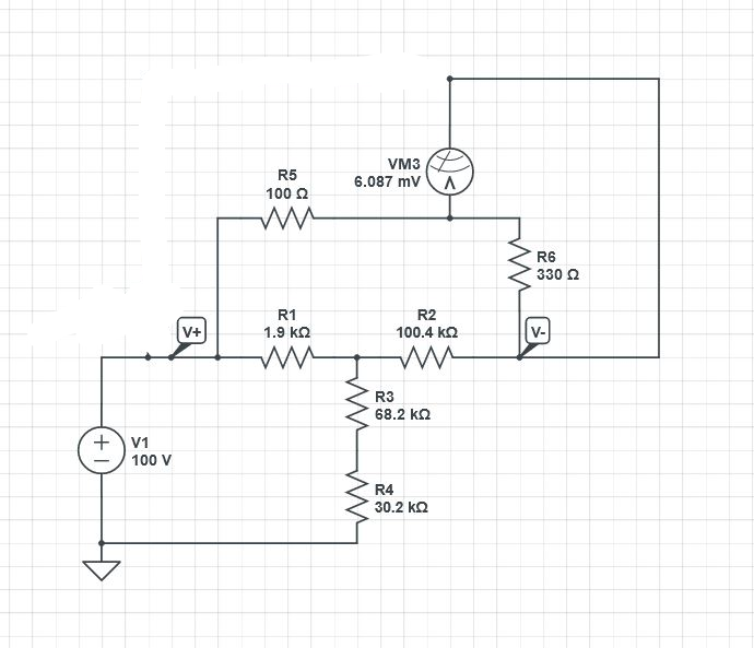
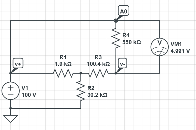
This wiring diagram is still a work in progress. Need to probably hook up some transistors for the stepper signals to the Arduino and figure out the THC circuitry on the Arduino shield next. And add limit switches/z-probe.
Wiring_Diagram_v0.1.pdf (318.2 KB)

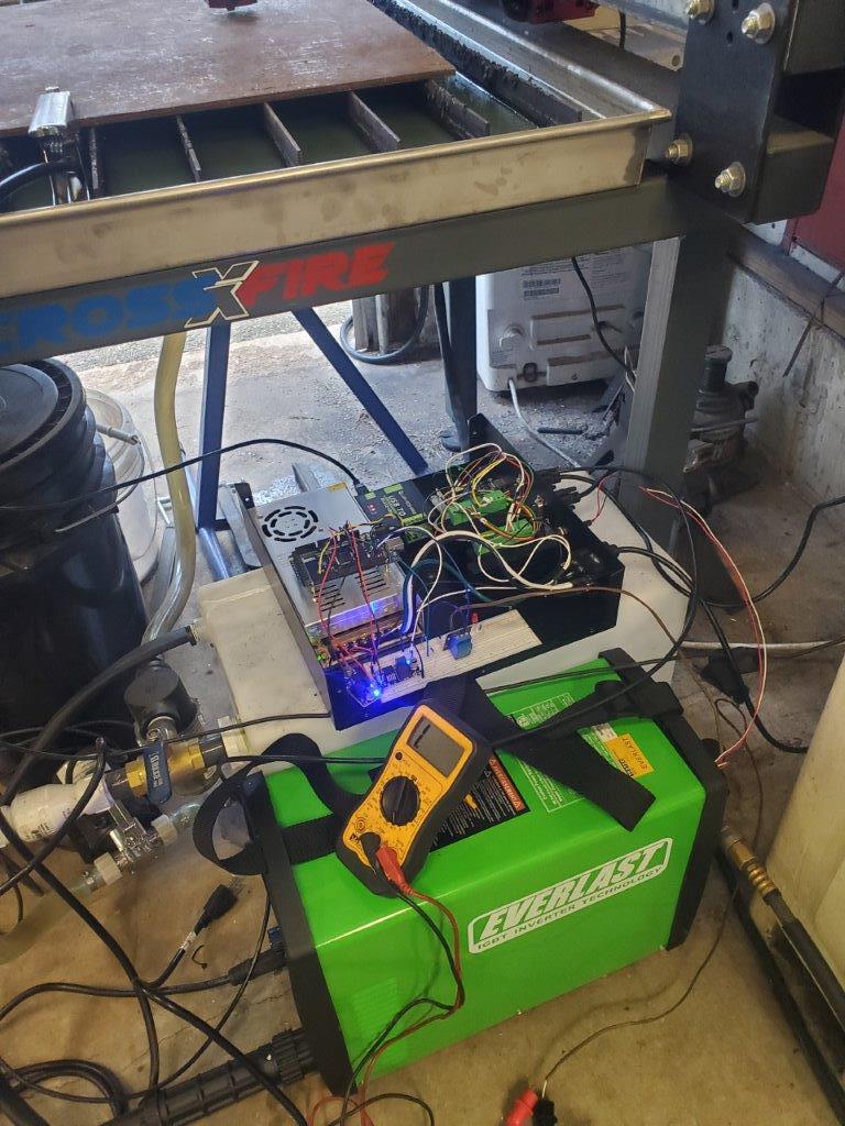
Here is a video of current state. I’ve worked and learned so hard to get this far and its been a ton of fun learning all this.

Disclaimer - I’m a Mechanical Engineer - blow up your stuff at your own risk :slight_smile: This will be a slow moving project.

References:
Shilling Systems Mach3 Modbus to Arduino Tutorial:

Physics Anonymous Mach3 Screenset:
http://www.physanon.com/pa-mach-3-screen-set/

Some other Langmuir user’s projects about how to utilize the existing BOB. Thank you @Burgs04, @Dicky and @TomWS - I have learned a lot from each of your posts!

2 Likes

Fascinating! I’m looking forward to watching your progress!
One question I have before I dig into this (it’s too late in my evening to give it its due) is why does the Arduino need to know anything about X or Y?
In general, THC doesn’t care about the other two axis, it only needs to know what’s going on with Z (and torch, of course).

1 Like

The intent of the XY input is to calculate velocity and use that in the anti dive controls. I think Mach3 has some algorithm for this but due to the signal delays with Modbus, it needs to happen on the Arduino in this setup.

Wow! It’s revelation to me that Mach 3 supports ModBus as a means to control devices. GREAT FIND! If I had only known… Looks like an easy and effective way to expand Mach 3’s control of the system. Presumably you’ll be using this to control THC operation (enable/disable) and it’s operating parameters?

The neat thing about using the Arduino platform is that it will be easy for you to move to other processors (with more memory or faster performance), not to mention that they are very inexpensive (and easy to roll your own PCB).

Re your comment about anti-dive. I’m not sure how that would work. If XY velocity is low, disable or slow down THC’s Z action?

Finally, the trickiest part of roll your own THC will be the voltage sense and track processing. The plasma voltage is noisy AND it needs to be electrically isolated from the rest of your electronics. I chose to go with THC3T for mostly this reason. That I didn’t want to be learning 12 things at once to get working THC was the other :wink: Good on you that you’re not daunted by this!

Looks like fun. If you need any help or information, feel free to PM me.

1 Like

I would definitely not call it easy (the Mach3 configuration anyways), but it does seem to be effective. Yes, that is the plan.

Correct

This is exactly what I’m doing! I’m in it for the journey as much as I am the end result with this project.

Very interesting indeed! :nerd_face:

Well I am for sure struggling with the Arduino code (I mean learning) . I’m trying to read the PUL and DIR from the BOB and output it from the Arduino. Never used interrupts before, so that’s taking some time, but making slow progress. Anyone really good with Arduino coding?

The Z_P pin on the BOB is normally low, right? Meaning the stepper steps when ZP rises?

Well, one problem you are going to have with that is that the pulse width of the PUL pin is between 5-8 microseconds long. There is no way you’ll capture that reliably by reading the pin. You may get a reliable interrupt when the pin changes state and be able to infer that it pulsed, but you won’t be able to read it with Arduino C code. FWIW, I believe the pin is normally high and pulses low, but I could be wrong about that. A voltmeter will tell you what its normal state is, however.

1 Like

[quote=“TomWS, post:8, topic:13792, full:true”]
Well, one problem you are going to have with that is that the pulse width of the PUL pin is between 5-8 microseconds long. There is no way you’ll capture that reliably by reading the pin. You may get a reliable interrupt when the pin changes state and be able to infer that it pulsed, but you won’t be able to read it with Arduino C code.[/quote]

I think you may be right. I haven’t given up on something like this, but decided to focus on the need to have stuff first, not the nice to have.

Apparently renovating a bathroom was needed to have, because that’s what I did in my free time the past month.

I have hooked up the Arduino to the plasma in the sketchiest way ever, just to grab some voltage measurements to see what the noise looks like so I can start piecing together a Digikey order. Turns out 18ga thermostat wire fits right into the CNC port terminals perfect!

I was expecting noise, especially without using any shieldling, but this was way worse than I expected. I had added a voltage divider outside of the machine because 16:1 could have sent 6.5v and the Arduino needs to read <5v. I thought I did the math right to get 5v max. (V+ and V- are the pins on the Everlast)

I was expecting a signal around 4v, whereas this is averaging .7v. After some more research, I had made two errors:

  • My plasma was set to 50:1 ratio, not 16:1. Oops.
  • The internal circuit inside the plasma is not a voltage divider, its a T Attenuator.

Since I forgot all the DiffEQ for that years ago, I used a circuit simulator. The circuit I created, would theoretically send 6mV to the Arduino. That probably explains why there are so many 0’s in my data and everything else is just noise. The ADC in the Arduino measures ~5mV/count.

So I think I need to go to 16:1 and change to something like this and try again. (A0 is the Arduino Analog in)
image

Just trying to see what the raw signal looks like, I plan to add filtering, shielding, etc. Hopefully I am not way off track!

1 Like

Well I’d say this is progress! Raw signal with the above circuit:

Added some caps for a quick and dirty filter:

I feel like that is borderline usable as is and I haven’t even placed my Digikey order yet. Its still not the nominal voltage I was expecting, but that really doesn’t matter as its just a relative measurement.

Something is weird with my millisecond timer too… it was spot on accurate yesterday but I made some tweaks to the code which seem to have thrown it off. This is .7sec worth of data for a cut that lasted about 6sec. I suppose the other possibility is the program is crashing after .7sec…

1 Like