Upgrading the control cabinet and adding a floating z axis with probing and other goodies. Stay tuned! Full write-up coming soon!
Alright then, patiently waiting.
You got my attention!
Here we go. First of many post. Thinking I will just keeping editing the main post to keep everything together.
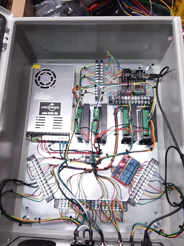
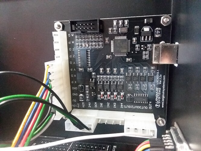
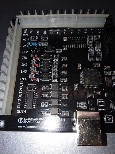
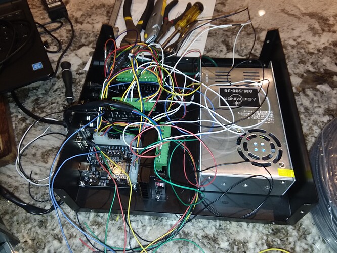
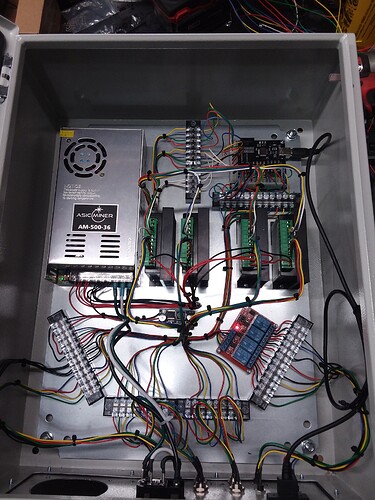
It all started with wanting to add an emergency button and torch ok to move which my plasma machine supports. I had issues with tip ups and torch not firing because of faulty consumables. So I started with taking pictures of the electronics enclosure and deciphering the bob (breakout board).
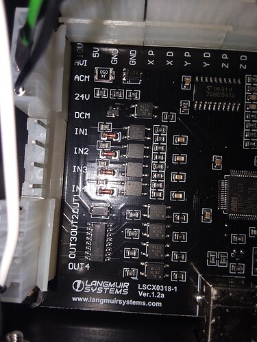
The ARM chip has many inputs and outputs and looks like most of them are populated. So inside mach 3 in the crossfire profile ports and pins output 1 is listed as port 3 pin 4 which is the torch on connector. So one could only guess that the other 3 outputs have to be port 3 pins 1, 2 and 3. Testing with a multimeter confirmed this guess. Sweet so now all the output pins are functional on the Bob and in mach 3.
Next I moved to input pins. Looking at the Bob and going thru the components of the input circuit and some testing with the multimeter you could tell that the pin was in a high state and needed a ground to activate the diode to drive the transistor low which would give the ARM chip an active low and should trigger the input in mach 3. Inside mach 3 there was no inputs listed. Start the guessing game. I activated every input there was 20 or 30 of them all with different ports and pins. Went to the diagnostic tab and ground out the input pins on the bob. Nothing lit up. Well crap. Back to the bob. Tested the input pin of the ARM chip to see if when I grounded out the input pin of the bob it too went to 0 volts. Nope it didn’t. A quick search on the ARM pdf revealed that it doesn’t go low until less then 1.25 volts or so on the ARM input. All I could get was 2.3v give or take when ground out. Next did the math on the input for the photodiode and found the the resistor value “302” was 3k ohms was incorrect for 5 volts which was coming from the usb. For the voltage at the diode to be correct the voltage coming into the resistor had to be in excess of 100v DC to fully light the led in the photodiode.
Must be a safety factor value or it didn’t need the full voltage to light the diode enough to close the circuit on the other side. If you notice there is a 24v marking next to the pin that’s getting 5v from the other header. Hooked up an external power supply of 24 volts and tada! I’m getting a signal in mach 3. Awesome! Well no. Now I need an external power supply to get the input pins to work. Crap. The minimum voltage that would trigger the input was 7.5 v. So I did the math and found that a 680 ohm resistor in the place of the 3k resistor should give the voltage I need with a bit of safety margin if I’m only using the 5v from the usb.
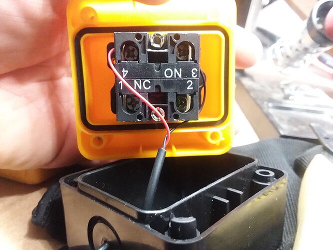
Sweet! Everything is finally working with only the 5v from the USB! I made a quick connection and got the e-stop button working on input 1 which is port 3 pin 1 on mach 3. Ground out to the switch and wire coming back goes to input 1.
Well hell… now I know all the pins for the inputs and outputs let’s move on to z and a axis. This was easy to figure out. If x is port 1 pin 2 and 3 and y is port 1 pin 4 and 5 then y must be port 1 pin 6 and 7 and a must be port 1 pin 8 and 9. Done with the motor side pinout.
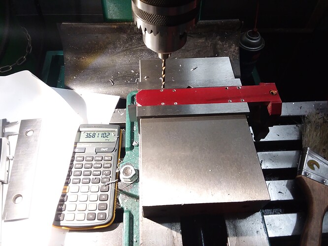
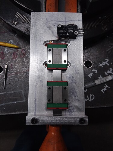
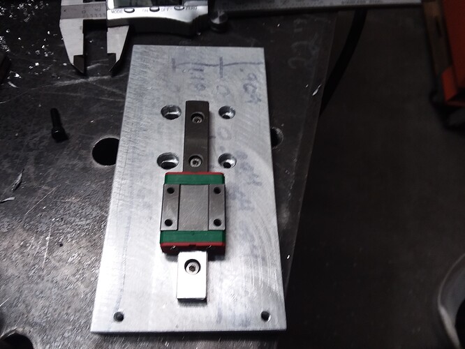
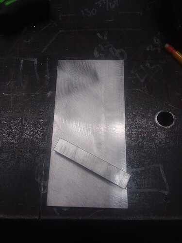
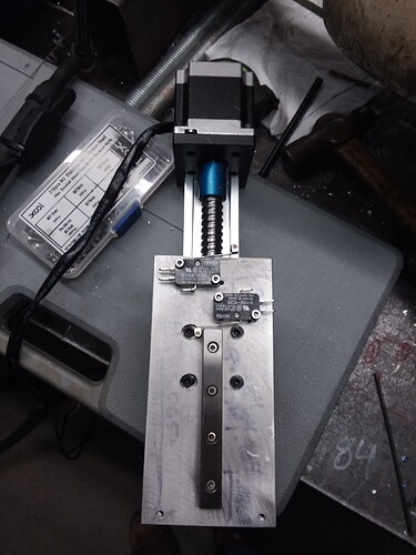
Now if I have everything labeled and working why not add a z axis.
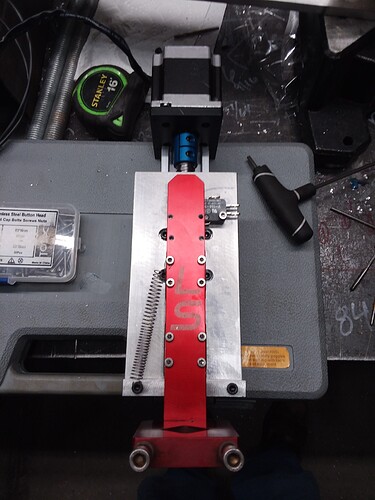
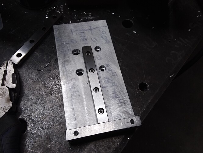
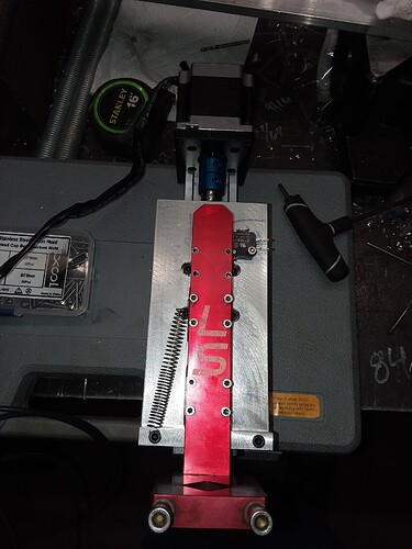
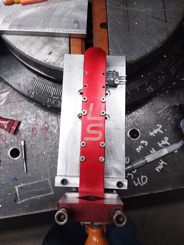
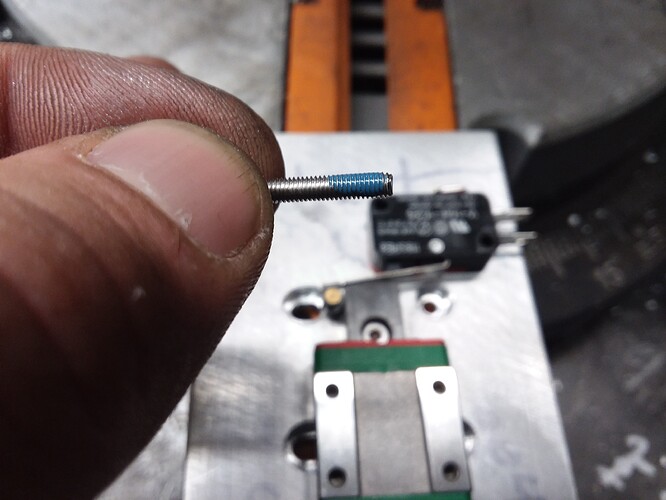
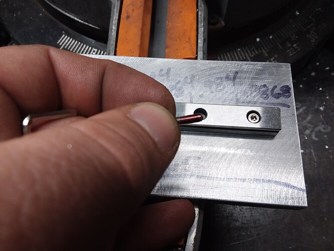
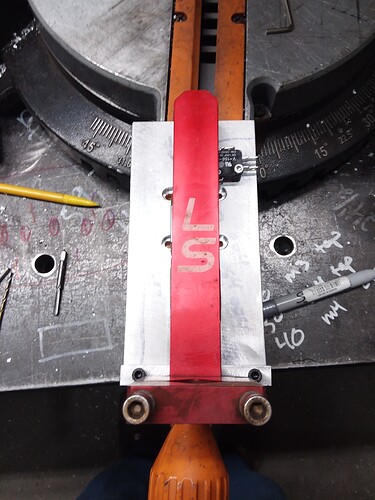
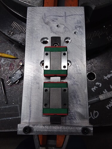
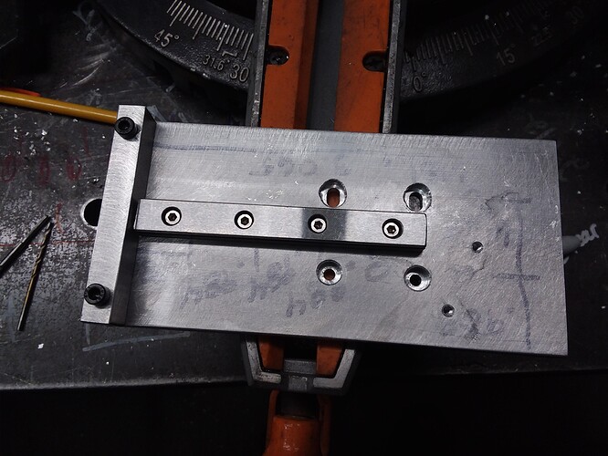
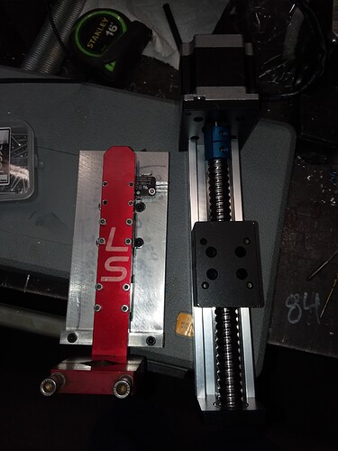
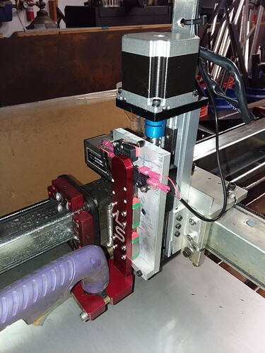
And if I have a z axis why not make it floating with switches for home and probing.
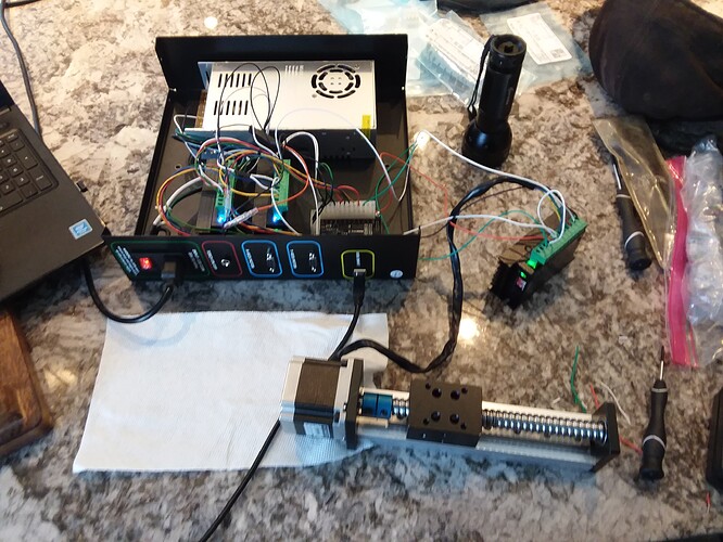
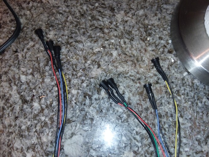
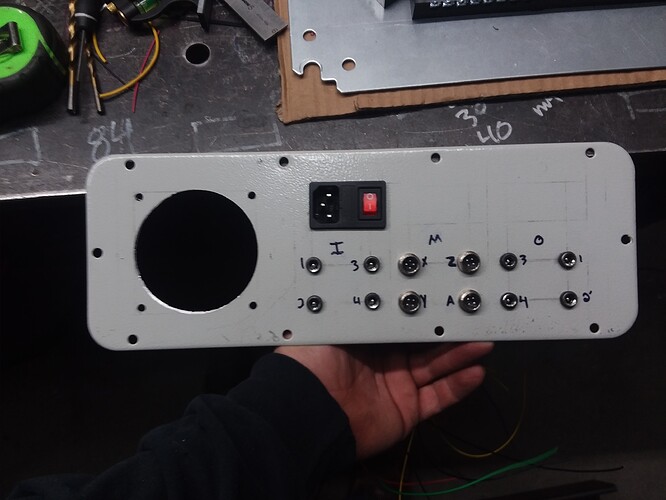
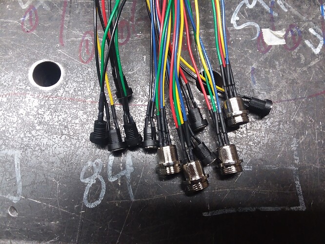
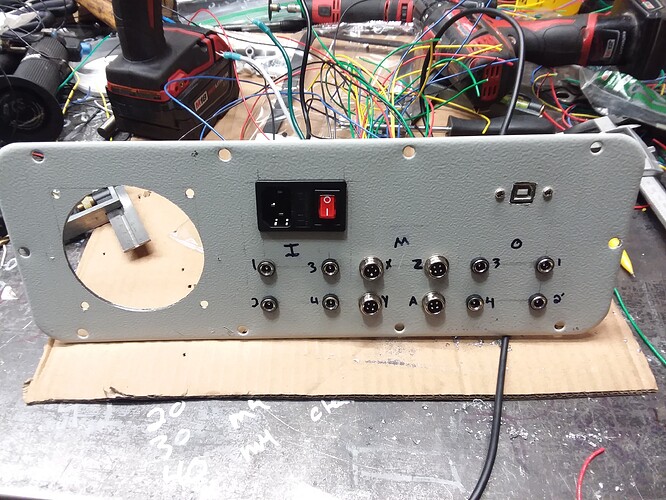
Now let’s add all the input and output connections and the z axis driver.
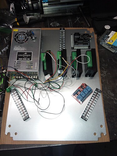
Also upgraded the power supply to 500 watts in the meantime.
Well this looks like crap.
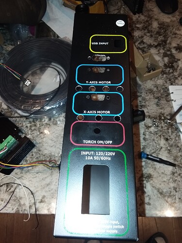
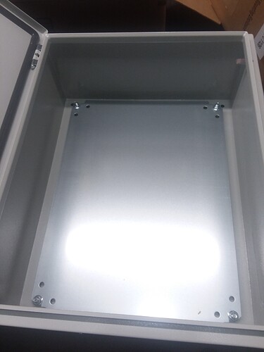
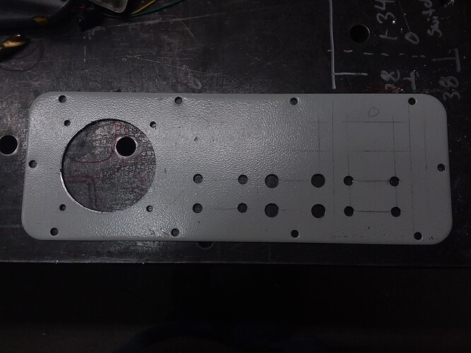
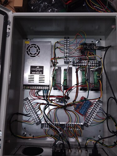
Time for a bigger cabinet. If I’m going to a bigger cabinet might as well go all out.
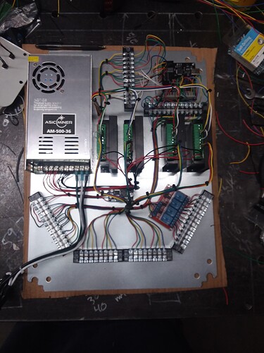
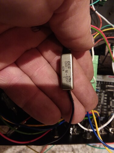
So now that I went all out I changed the resistor back to 3k ohms put in a 36v-12v power converter to supply all my inputs and outputs and take the load off my the USB. USB usually is only good for 500 ma and that ain’t much. So instead of having a bunch of Reed relays to control the outputs, which what langmuir had in originally.
I changed it out to a 4 position relay board with no and nc contacts. Shown in bottom right of cabinet photo with the blue relays.
Now I’m at the point of installation back onto the machine. Next update in a few days.
So bad ass!!! Thanks man.
Wow. Very impressive! I know very little about this stuff but I am learning all that I can in hope of building a rotary tube notcher that will utilize one of the axis of the crossfire. I will be following intently and trying to learn as much as possible from your journey!
Thank you! Any questions just ask. I’ll try my best to answer them as they come.
Thinking that’s what I’m going to do with the a axis. Set it up as a removable rotary axis. As soon as I get everything mounted and installed it will be time for that and possibly a thc!
@Burgs04 I cant wrap my head around how to take the profile around the circumference of the tube and turn it into a flat profile to be translated to the rotary axis. Im excited to continue to learn. The extent of my knowledge is from watching ThisOldTony build his router on youtube. lol
At this time I’m thinking the way would be to have your layout in fusion. Draw a square with the length being your tube length and width being your circumference. Draw your design in that space and post g code as you normally would.
Could use different profiles and make a z or a axis your rotary axis but wouldn’t be marked as a rotary axis.
In mach 3 you would change your steps per inch in motor tuning based on circumference of your pipe. So let’s say 1.8 degree per step, 32 micro stepping are your settings with a direct drive stepper. This would be 360/1.8 degree x 32 = 6400 steps per revolution. If your pipe circumference is 2 inch od x 3.14 = 6.28 inch circumference, you would take 6400 steps per revolution/ 6.28 inch per revolution ~ 1019 steps per inch. This would be you setting in the motor tuning in mach 3.
Now of course you couldn’t have a design go all the way around your pipe but it would be a start.
I think sheetcam has a rotary plugin and I might mess around with it when the time comes.
Awesome. that answers a couple of my questions.
Why wouldn’t you be able to go all the way around the tube?
I would be using it for coping tubes for rollcages, etc. My thought was to draw up a model of intersecting tubes in solidworks that would automatically update the tube notch when you change the angle. You change the angle, unroll the tube profile and you should have your 2d geometry.
Now i just need to work on the unroll function in Solidworks and see if i can get it working well.
In that situation it would work cause your cut would end where it started. But let’s say you had circle cutouts in the tube and they were above one another but offset by a 1/4 turn. This would be difficult to achieve a clean cut as where the edges of your material are in 2d would leave a small nib when cut because that is where your start and stop points are. A little clean up with a die grinder would take care of it. Does this make any sense lol.
Makes total sense! Thanks!
Please keep this thread focused on the table modification and upgrade. Start another thread of chat that isn’t directly about what is going on in this thread
Thank You
Rich
Floating Z Axis Dry Run
Z Axis Homing / Limit Switch
Awesome your doing all the hard work for me. Ha ha I bout the stepper controller and the motor hooked it up for a dry run then got busy and haven’t touched it. I’m very impressed thanks for the post.
What did you end of connecting to your 4 inputs and 3 outputs?
Input 1 z probing
Input 2 z limit
Input 3 e stop
Input 4 torch on from plasma
Output 1 torch on to plasma
