Absolutely not a solution. Start a thread @Wsidr1. Let’s get you figured out too. ![]()
I have a thick rubber strip between the control box and the frame leg it is mounted to.
I did that during my original assembly. I have the isolating washers on the screws which attach the control box to that leg.
However, I have continuity between the control box cover screws and the table frame. So, I assume it is the threads of the control box mounting screws to the table leg which are the pathway.
I also show continuity between all but one of the axis motor DB-9 connectors on the control box and the table.
Edit:
Maybe my next step should be to divorce the control box from the frame?
My control box is mounted up on the wall. I did this a while ago when I was running an everlast 60s.
I had a thought about finding these contact points that are completing the circuit by using a Megaohmmeter. I use a Megaohmmeter at work to test a compressor’s insulated windings. It’s basically the same as an OHM meter just with more power. It would definitely be destructive testing but it would ultimately let you know where the loop is being closed.
This was just a wild thought I was having.
3 Likes
Neither the washers nor that rubber pad will protect the screws from contacting the edge of the holes through the electronics enclosure. So unless you also have rubber grommets in those screw holes, you probably still have some metal to metal contact there.
The plastic 3 hole standoff that Langmuir currently supplies with newer machines has raised bosses that extend through the holes and, along with the plastic washers, does a decent job of isolating the screws.
3 Likes
You can also get washers that have a built in sleeve that work.
3 Likes
As @Martorious points out the plastic stand-off from the leg along with the plastic washers insulate the screws from the control box. I think in this case you present the screws will conduct through the edges. If you take control box off the leg do you still have continuity?
1 Like
Can we please move this discussion to a new topic?
4 Likes
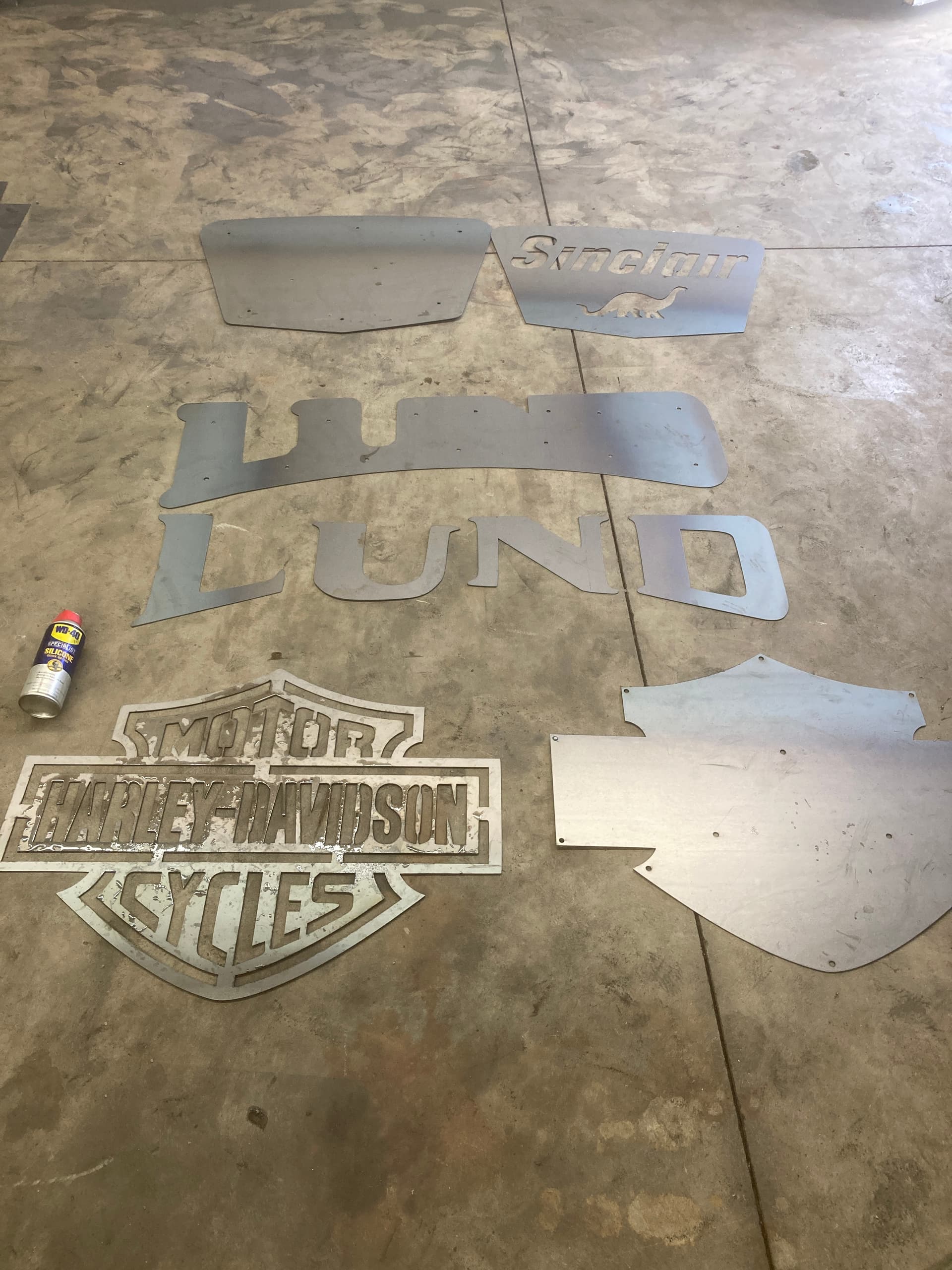
Got these cut out for my pole barn this morning. Just need to paint and put together. I added the WD can for scale of signs. I only do these for myself not for sale. This is hobby not business. Wish i could post lot of my layered signs but i believe it’s again the rules. Layering signs is something i got into few months ago and they look so much better than standard 2D when completed. i design them to make it easy to add the hidden studs in the back. i’ll post when completed if people are interested.
6 Likes
I do a lot of multiple layers. I even space some for lights. I is some of my last ones I did
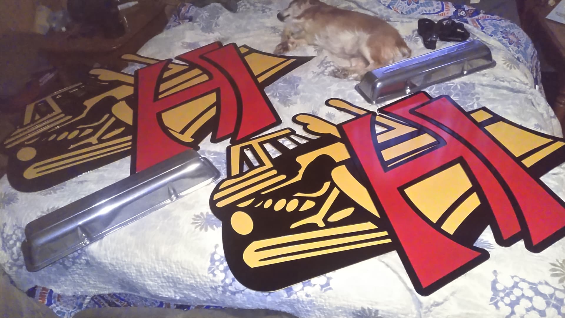
Look over the dog she belongs to the neighbors.
3 Likes
@Phillipw, I’m working on my first multi layer sign and I want to back light it. Is it too ambitious to have multiple light colors?
1 Like
I would not think so. You may want to cut you pieces and put light behind it to see how they blend. You may need to put dividers on the back to block the different colors.
Most of my backlit signs I tig 1/4 studs to the front plate and make spacers out of 1 inch tubing. I usually tell whoever get the piece to go buy magnetic puck lights they are some of those that can change colors also.
I have some plexiglass it put between layers I want to try some frosted paint on one and see how it changes the effect.
3 Likes
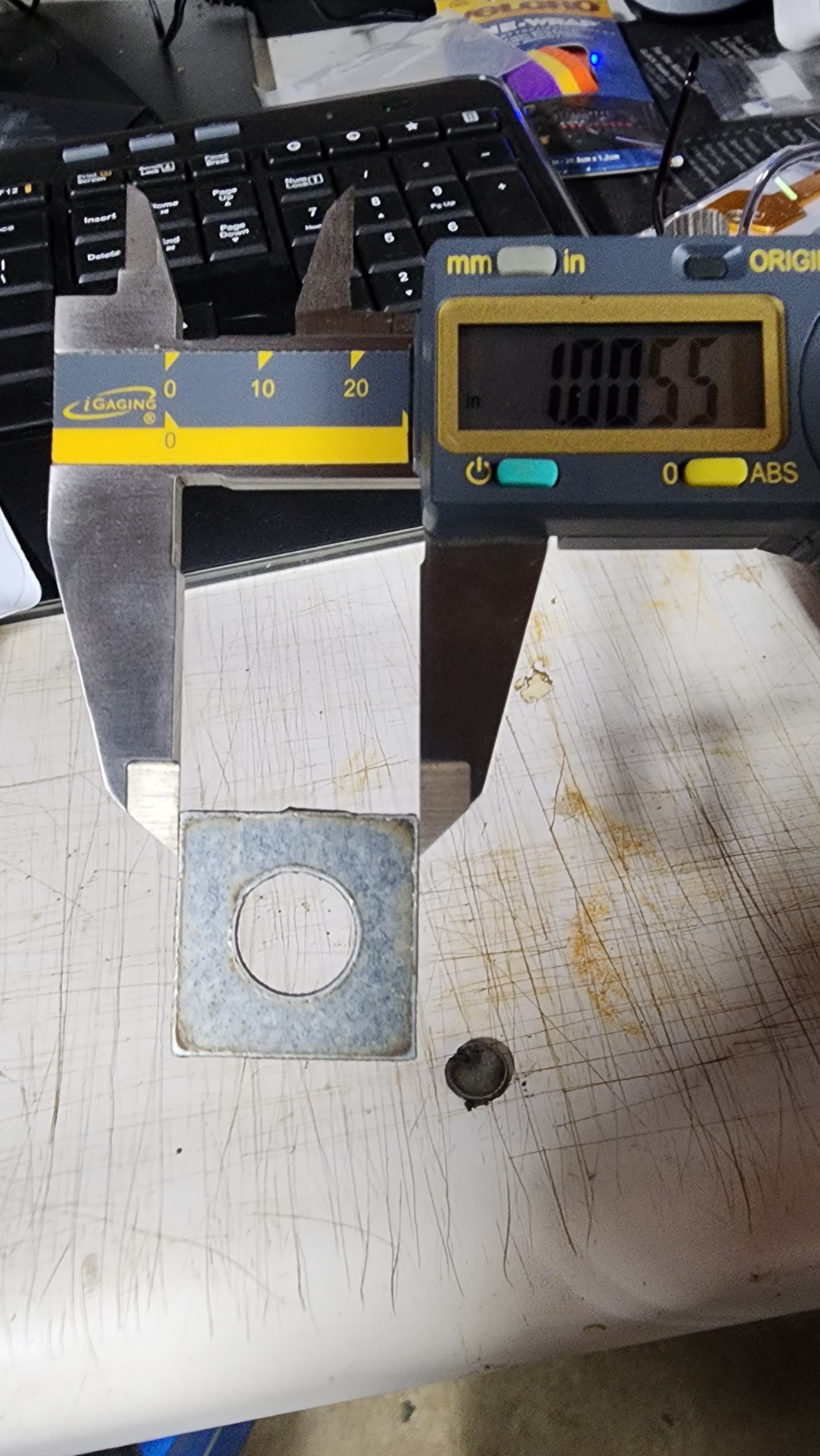
OK, not the most impressive of parts, but my first part designed, manufactured and post processed entirely in F360 by me. But it was square, and within 5 thousandths of size. I’ll take that as a win!
9 Likes
My first parts were also real simple. Brackets for some pallet forks for my tractor. But I was super proud and happy they actually cut.

Looking back and remembering how little I knew about the CAM settings, I’m still amazed they cut so clean.
5 Likes
I’m planning on dividers as the tree I think will be green and the matini blue… I was thinking 1/2 to 1" distance between layer 1 and the backer does that sound about right?
1 Like

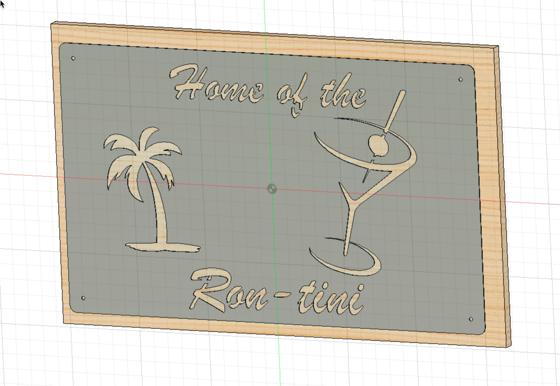
Very cool, what is the rough dimension of that sign and roughly how many LEDs if you remember. TY

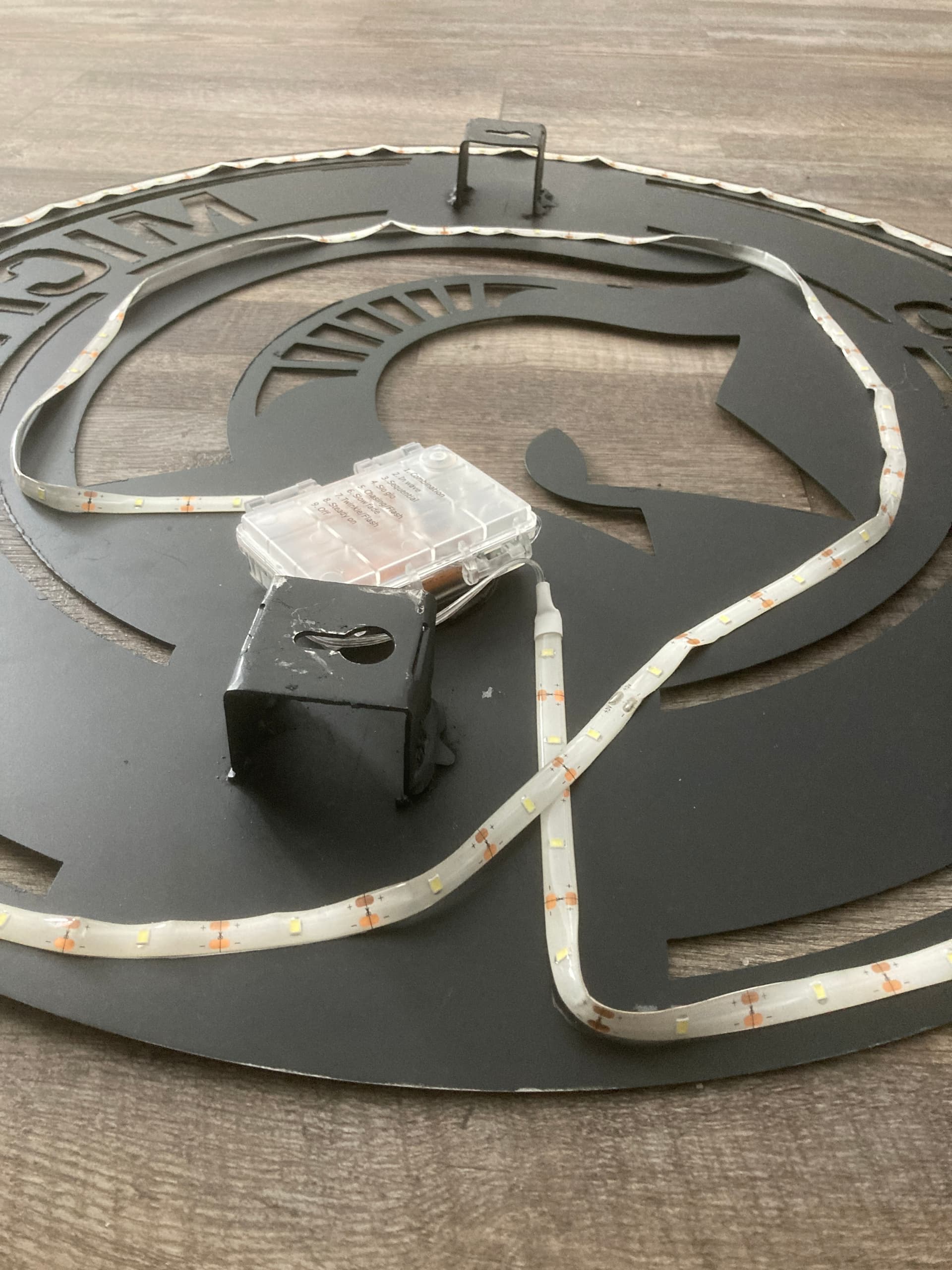


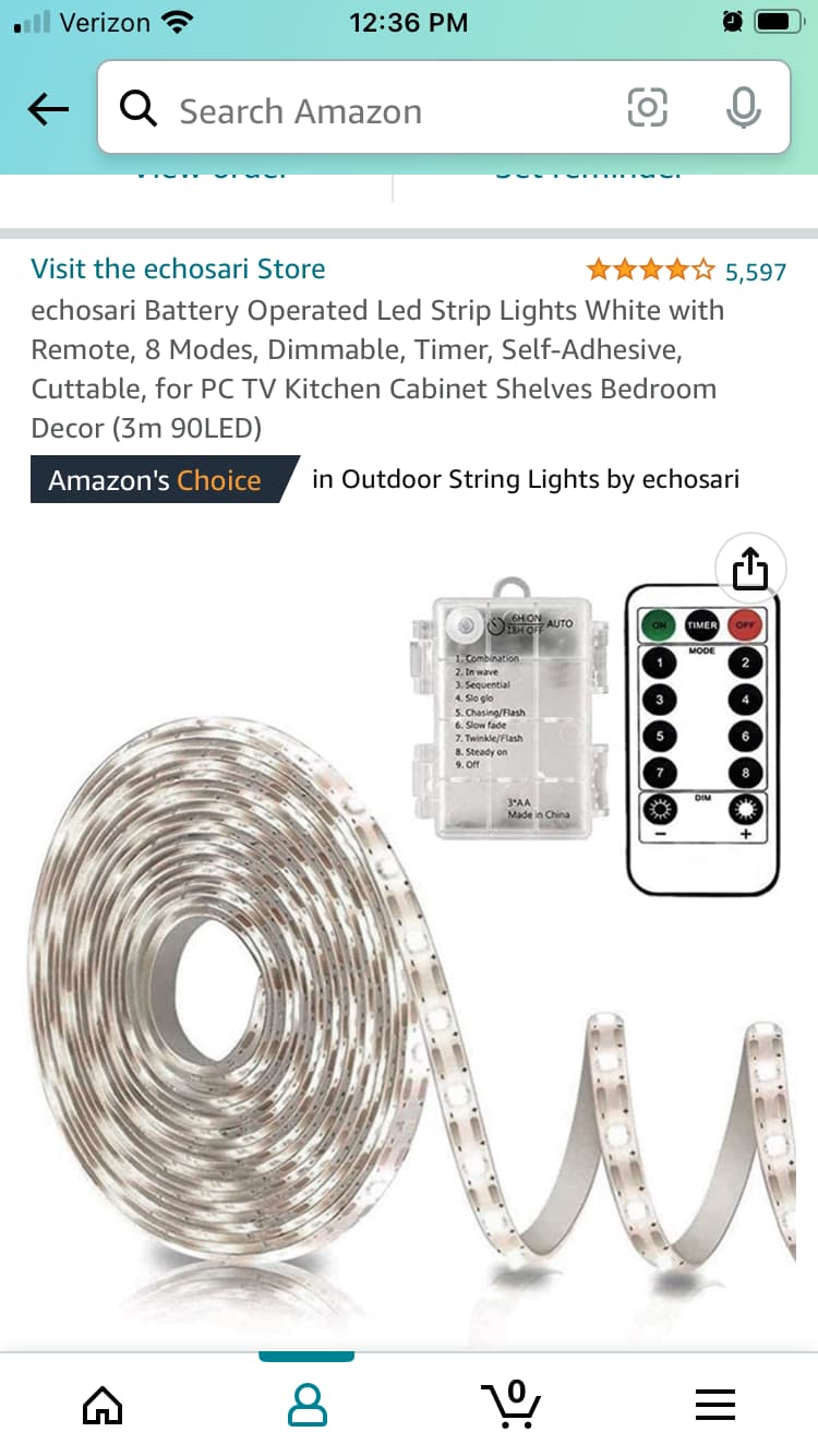
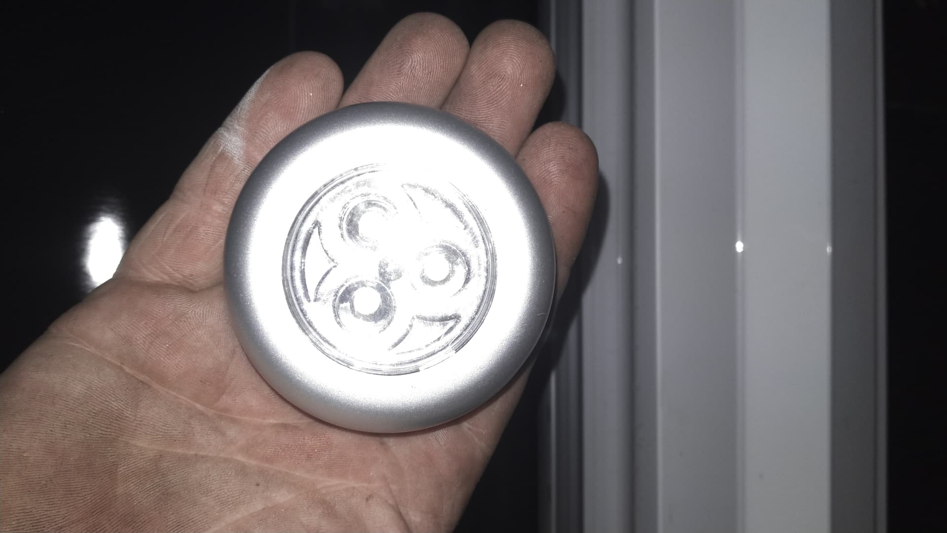
This was a sign a did months ago and have got way more advanced these days with stud welder. The easiest way to add lights is make a standoff that gives you the spacing 1"-2" from wall like one on this MSU sign. I recommend the battery lights because they last a long time and no cords. My son uses this in his room almost every night for last few months and never changed the batteries yet. $12 and comes with remote and you just stick it on. i did glue on the battery box in a way that i can change the batteries when needed. The standoff needs to far enough from wall to stick this battery box on without touching if that makes sense. I’ll post some weld on brackets or i guess you could buy some strong adhesive if you don’t have a welder if the sign isn’t too heavy. i use a threaded stud gun but there very expensive. I’ll post how i do it these days later tonight.
7 Likes
Thanks Don appreciate the ideas! I was wondering about the battery idea seems like a lot cleaner install! I do have Mig and tig here so I can do the brackets and standoffs. Looking forward to your other pictures!
i went and made you some sign brackets to give you 1.5" spacing so you can add lights.
1.5" wall mount for lights | FireShare | Langmuir Systems
4 Likes