Your pierce delay is too long, try .3
i also choose “Always inside” or “Always outside” depending which i’m doing. I believe most people use “left” side of compensation but i don’t because i use fine cut and dialed my cuts using Center. Whatever you do make them the defalt so you don’t have to switch them every time. Only time i change the lead in degree is if i’m cutting straight lines like relief cuts…i sitch to 0 degree. if cutting small circles i might need to change the lead-in radius to smaller number like 0.02 or 0. Sorry i know this is a lot of information but not sure what helps or not. I had to learn all of this stuff on my own it just takes time.
i believe the book says .04 but i’ve never had an issue using 0.06. So like a wise guy told me years ago “if it isn’t broke don’t fix it”…lol i might switch to .04 which really isn’t big deal. i appreciate the help
The lowest I’ve been able to enter without a FCtrl fault is 0.6. It’s probably because of the lead-in parameters I set, so I will keep trying to go lower as I get better at those settings.
Thanks for the advice.
Thanks for the reply. I am definitely going to use your lead-in numbers and several other things. I do usually leave left compensation except on single line.
Since the update a week or so ago, F360 has gotten good about using inside for closed loops and outside for outer loops which are my usual choices. I’ll confirm closely before I post.
I’ve been using 0.9 kerf on the 40 amp tip, 0.06 cut height, 0.08 pierce height, 65psi, 30 amps at 125ipm. Any values that seem strange I may have fat fingered. I do everything in metric system and sometimes don’t notice if I screw up a conversion. ![]()
I took your dxf file and did my best to dumb it down for my capabilities. Increased a lot of withs and clearances and simplified some stuff just out of fear. If I get it cut today, I’ll definitely be on here bragging… or asking for help.
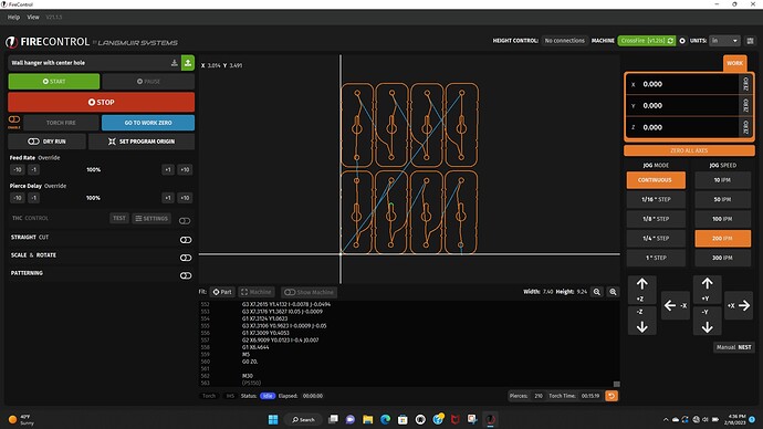
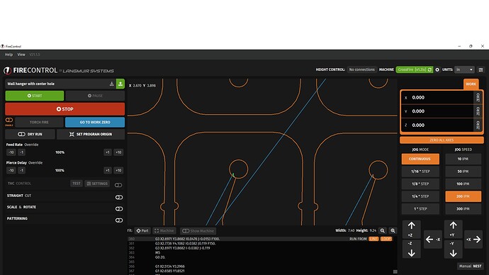
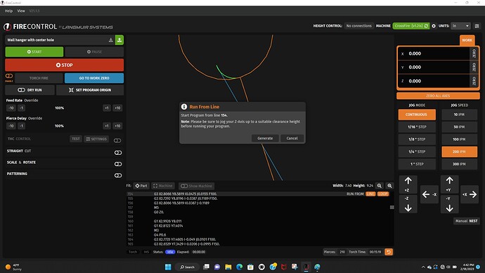
in firecontrol you can pause and let your compressor pump back up if needed. If a piece don’t cut out correctly you can always go back to theat one and generate from that spot. I’m going out to cut a mini bike motor bracket so i’ll take few screen shots becuase its really handly to know how to do it.
So i did try the 0.4 just few minutes ago and every letter was still fixed in sign by small uncut portion. i came back in and created my G-code using 0.6 and every letter was cut completely. Might be due to me running at 40amps and using fine tip. anyways i’ll keep using my setting. Never know until you try.
When you’re in fircontrol if you have a part that don’t cut or issue and stop in middle like error you can have it start wherever by going to the lead in for part you’re trying to cut and highlighted it and hitting the orange line button. It will ask if you want to generate cut path from that spot and say yes. The one thing you have to do is start from the original work zero spot. If you don’t it starts from the wrong position. hopefully this helps with future errors. like i said you can pause allow compressor to catch up and hit resume if worried about the long run time. I live in Michigan and had some issues with air condensation from compressor so added new motor guard M60 which seems to fix issue. just change out the roll of tolietpaper weekly…lol
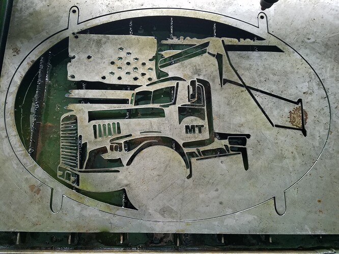
Crash and burn!
I didn’t have a piece of 16 gauge big enough. Thought I’d try 18 gauge just to get one cut.
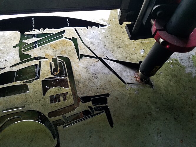
As expected, FCtrl froze on line 709. Program kept running until it found a spot where there was a weak point and Z axis pushed down to near water level. It might have been strong enough in 16 gauge, but I will go back and add a tab anyway. As I said in an earlier post, I made a lot of changes to this Fireshare file, so I must have screwed up the strength of that section. It was looking pretty good though cut quality wise.
FCtrl did “unfreeze” and let me try to regenerate and try again, but it left out a bunch of the code so it’s scrap.
i don’t have THC but its a great thing when it’s working correctly. You could turn it off and just manually set the height around .06 to .07. Thats what i run and never seem to have any issues.
I almost wonder if its the computer
it was looking good
That 18 gauge had a bit of contour from a previous cut. It’s a learning point for me to look for those weak places and add tabs. I’ll get it next time!
i just downloaded the truck and going to look over the file. I do agree you want thicker steel like 14 to 11 in my opinion for that cut. GL
I downloaded it and it’s cool design. i would do a bunch of clean up before i would cut it. sound like your on it. Lots of really small spots and if your running normal tip your going to have lots of issues. i switched to fine cut myself which allowed me to do really small letters.
Im not sure how many design changes that has gone through but originally I cut and posted it in 16 gauge using torch height control. It did ok. I wonder if you could put a piece of expanded metal behind it while you cut.
when you are working with it in your design program, you might make you stroke the actual size of your kerf, that will show potential issues where lines might touch that you cant guess. what size are you cutting it to? I had to do that with a real kerf of .034, which is fairly narrow.
That’s more or less what I was doing, plus some margin. The design is great. I was just paranoid about getting it to cut well since it had so much more detail than things I had cut previously.
I am sure I am the reason that section collapsed and caused my misfire. I will probably wait until I can get some 16 gauge in a few days. Give me time to correect my mistakes in Fusion.
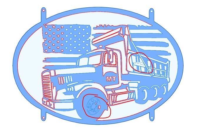
Here is what the drawing looks like as I tried to cut. I think I have addressed the areas you outlined.
Triax.dxf (637.6 KB)
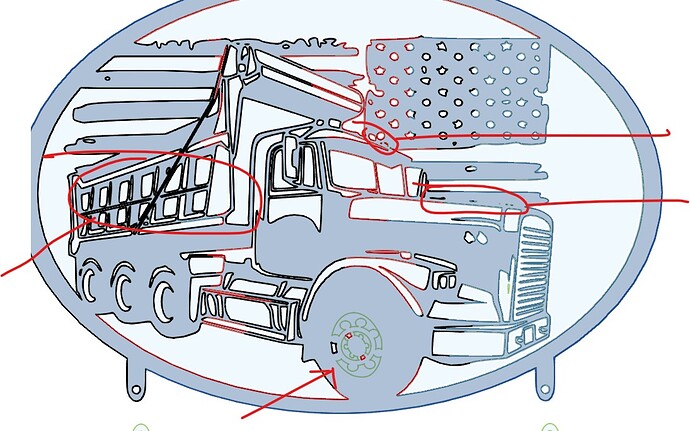
Your truck looks great. when i downloaded it and put in my fusion i see a couple things not in your drawing. This might be an issue with the dxf file and not your issue. I personally would go to any really small area and contour it and add the metal back to make sure you don’t have an issue.
