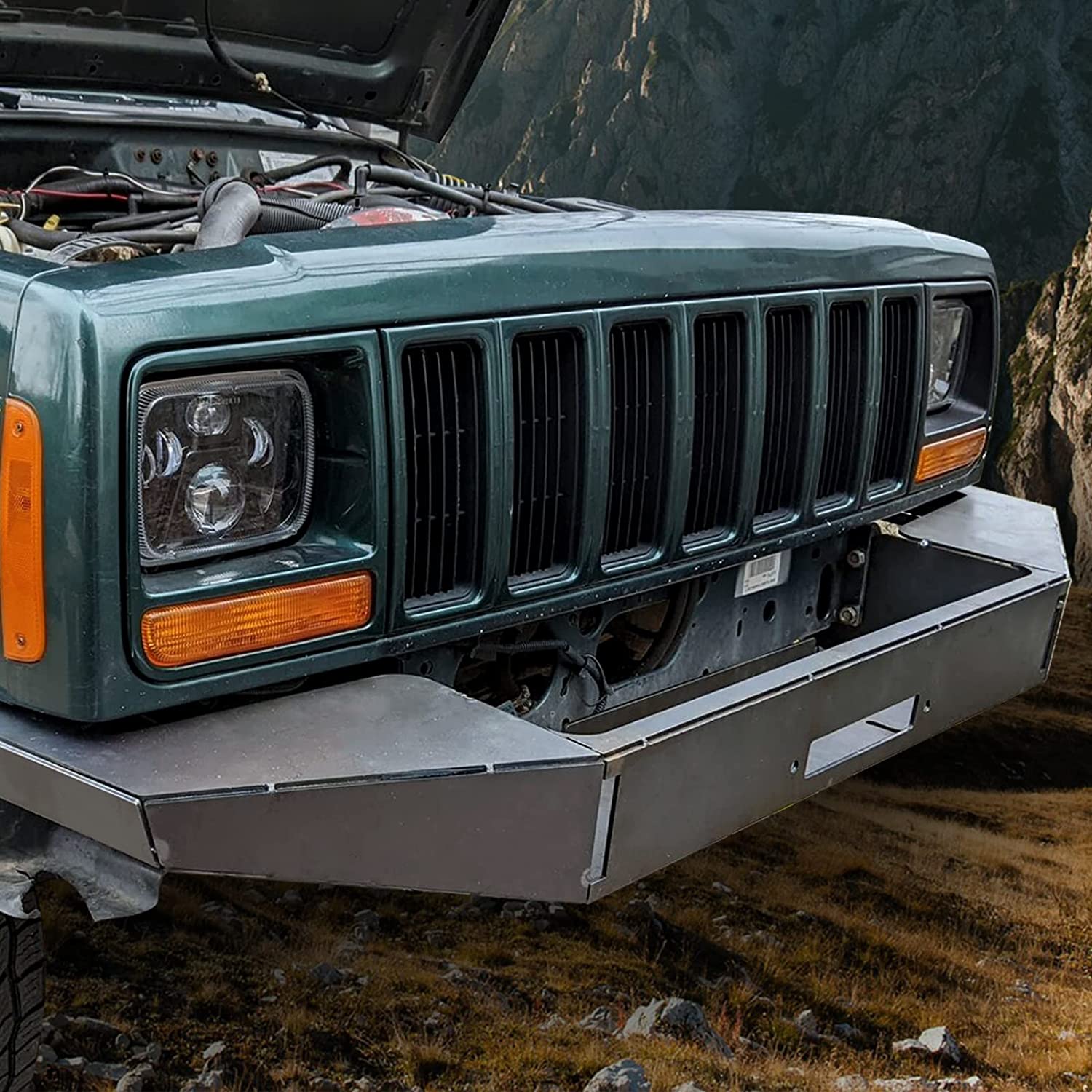
Hey everyone! I hope your weekends are going well. I am here because I have gotten pretty comfortable with 2d design, and have been recently trying to start learning the sheet metal factor. As it will be very handy for me in the things that i want to build in the future. I had high hopes because i seemed to pick up the 2d stuff fairly quickly. Boy was i wrong. I have been watching youtube pretty much all night and still struggling with what i am trying to do. My main goal is to be able to design a bumper for my jeep and maybe a couple buddies. I understand the flange control. and am starting to grasp the sheet metal rules. but i can not for the life of me figure out how to go back and add a part once in the sheet metal design. or how to add holes. I will post of picture of the type of stuff i am trying to do. I know there are a lot of good guys here and im sure something will click once explained to me.
Tinwhisperer is the guy that can help you with fusion. He has vids.
JEEP = just empty every pocket. couldn’t help myself.
Ive been doing some 3d stuff but just laying it out in 2d with cardboard or paper and putting in bend lines and individual parts. Following to see what I can learn however.
@TinWhisperer he might make you a video for what you’re asking. Much better to see a video. Glad you’re starting into 3D designs. Not sure what plasma table you have but when you start doing 3D you might be limited by size of table and your bender.
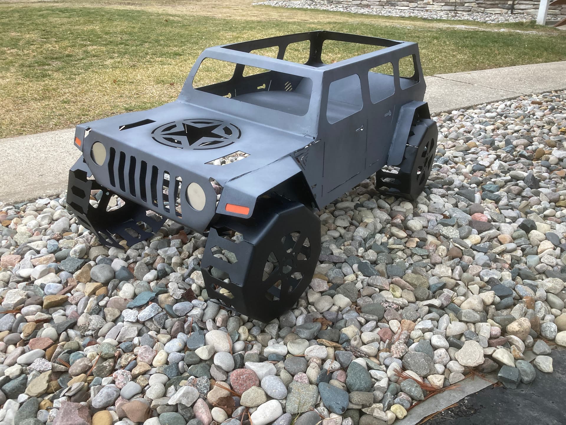
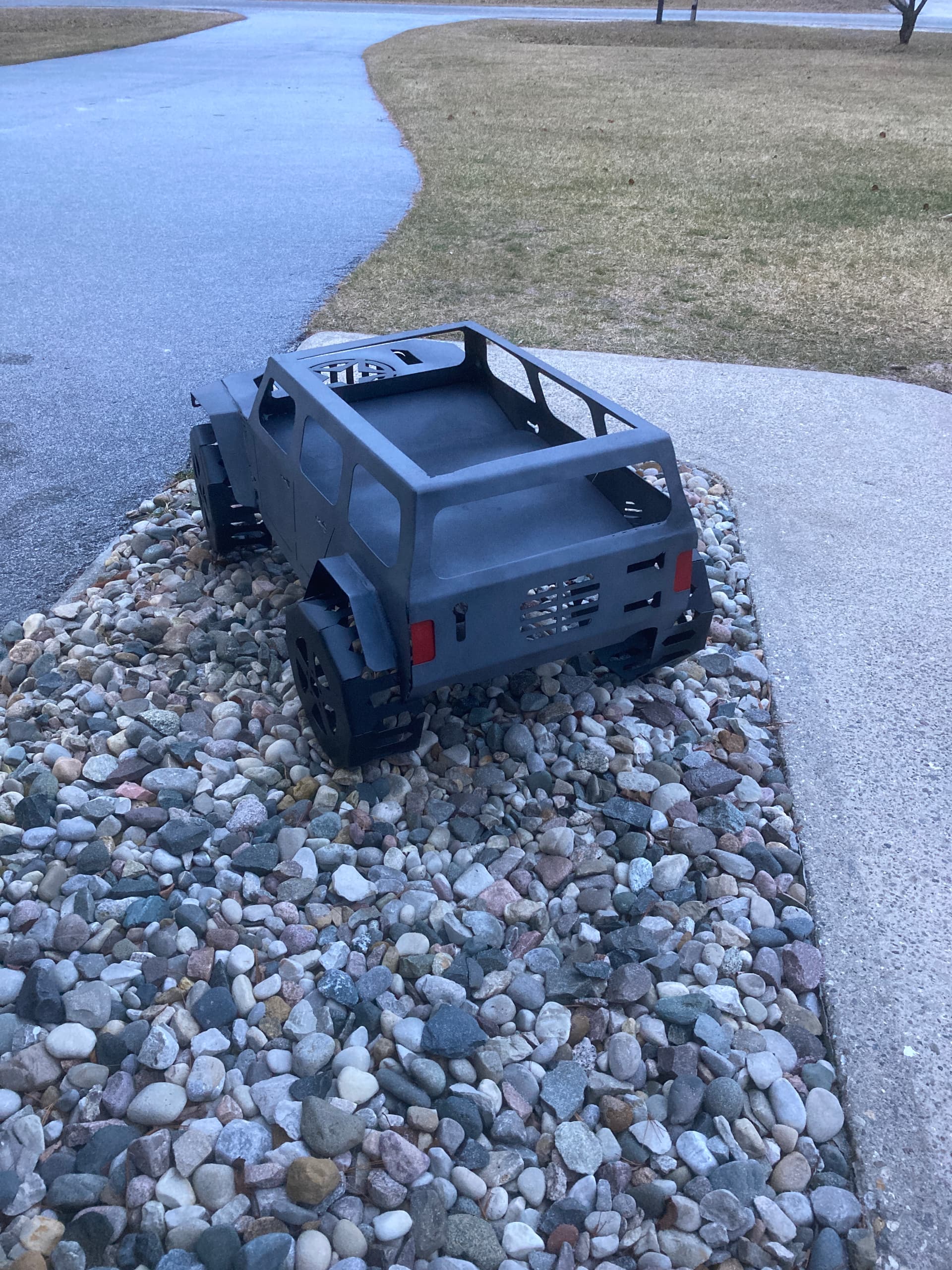
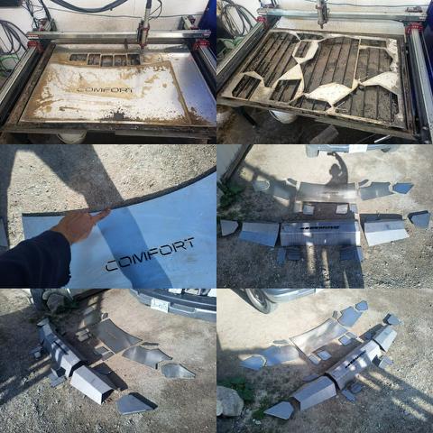
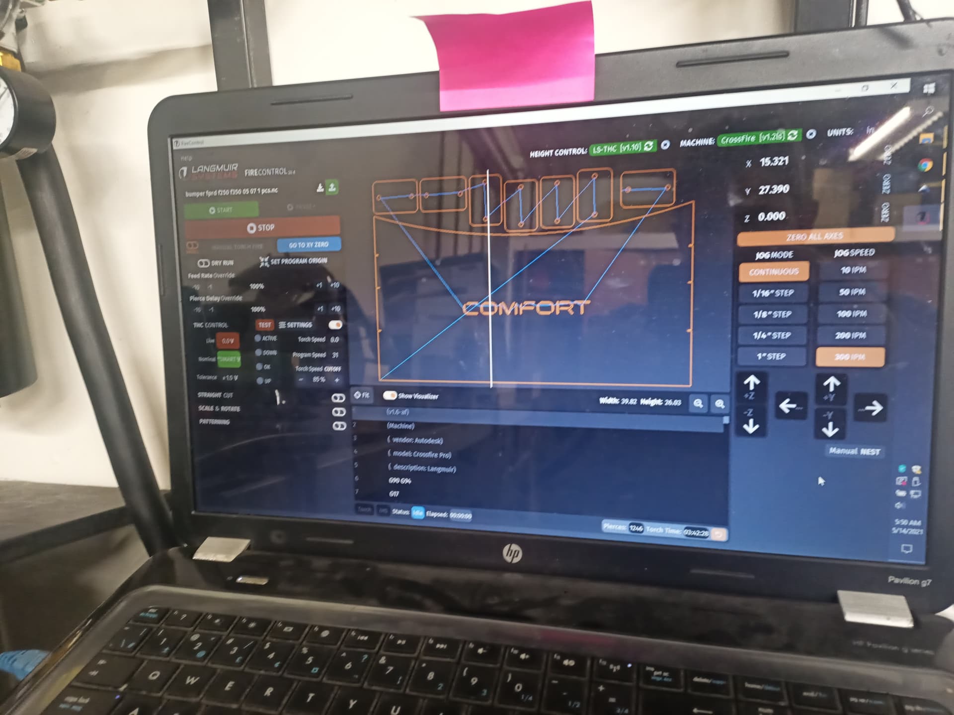
This was the only design i have ever purchased from etsy. I had to see how he made it. Very cool project to get you going on 3D. I didn’t spend much time making it and screwed up some of the bends but still looks like a jeep. i wish i could send you the file but i can’t due to rules. You can purchase yourself from etsy. Some really cool stuff you can make in 3D.
Scale it and do a body swap on an old power wheels. Better get some padding ![]()
A couple of things to identify within Fusion. A multi-part design is an assembly. A single-part design is a component. When designing an assembly, save it right off the bat, with no included parts (components.) Then add components as needed.
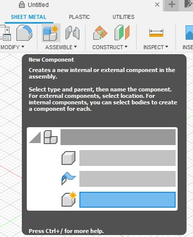
Each additional component can be defined as solid or sheet metal. Then use joints to connect them.
As far as adding holes, create a sketch on the surface you wish to modify and either add points (use the hole tool), or draw your holes as circles and extrude / cut.
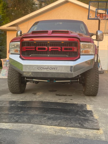
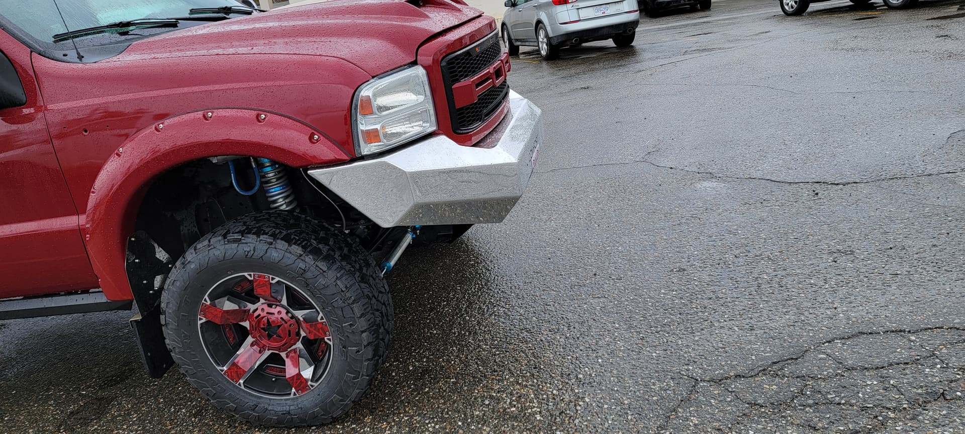
@asummers509 The bumper you posted the link for would not require the use of the sheet metal part of fusion 360 .
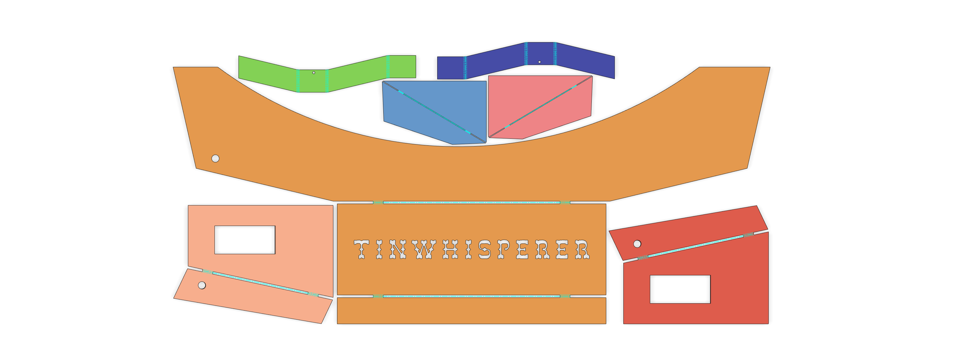
Sheet metal components are used to bend compensate for bend allowances. The picture of that jeep bumper has no bend components, it is several flat pieces tacked together.
@Simsworx is right, using proper file structure is critical when dealing with more then one sheet metal component .
So considering there is no bent parts in the example I could put together a video on how in go about creating it with simple bodies instead.
I’ll try to live stream something in the next couple hours.
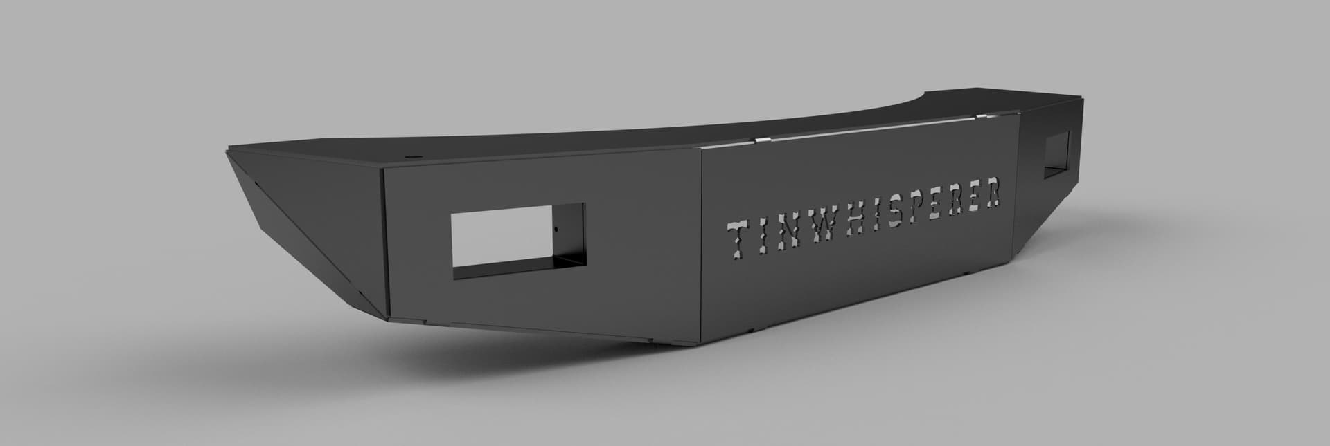
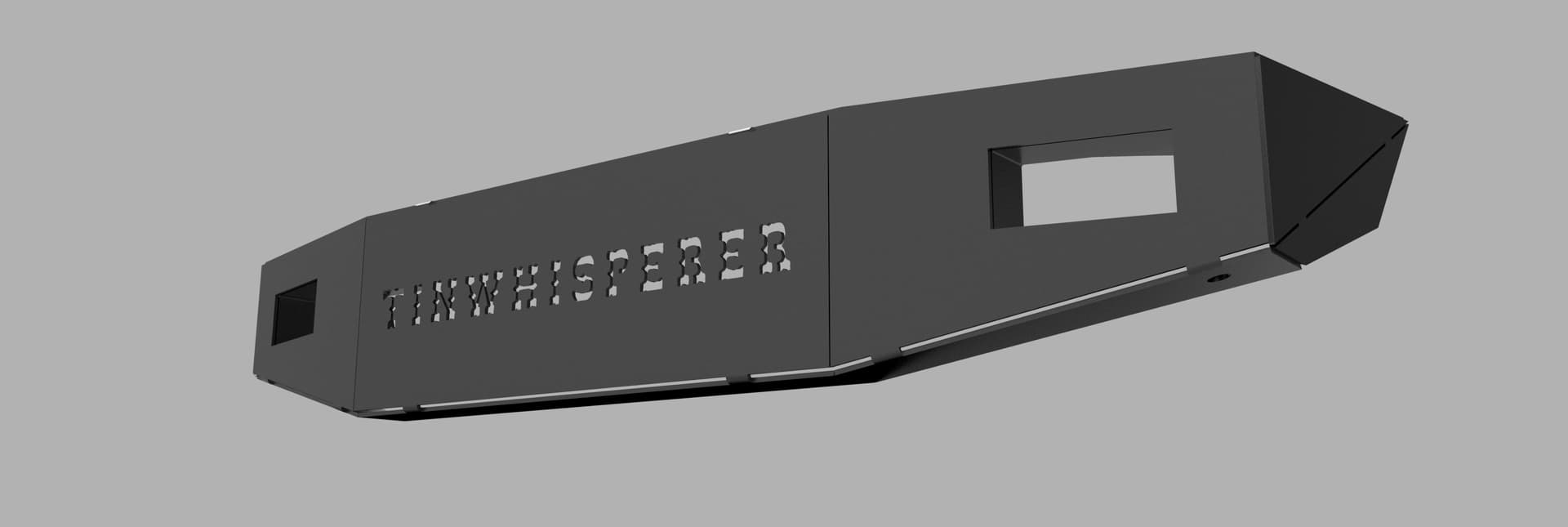
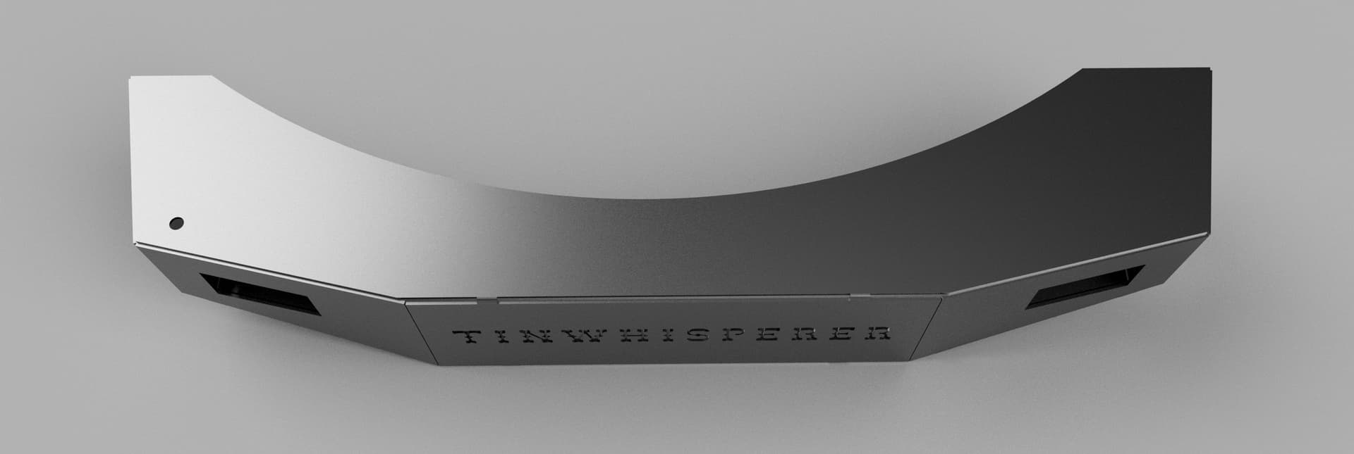
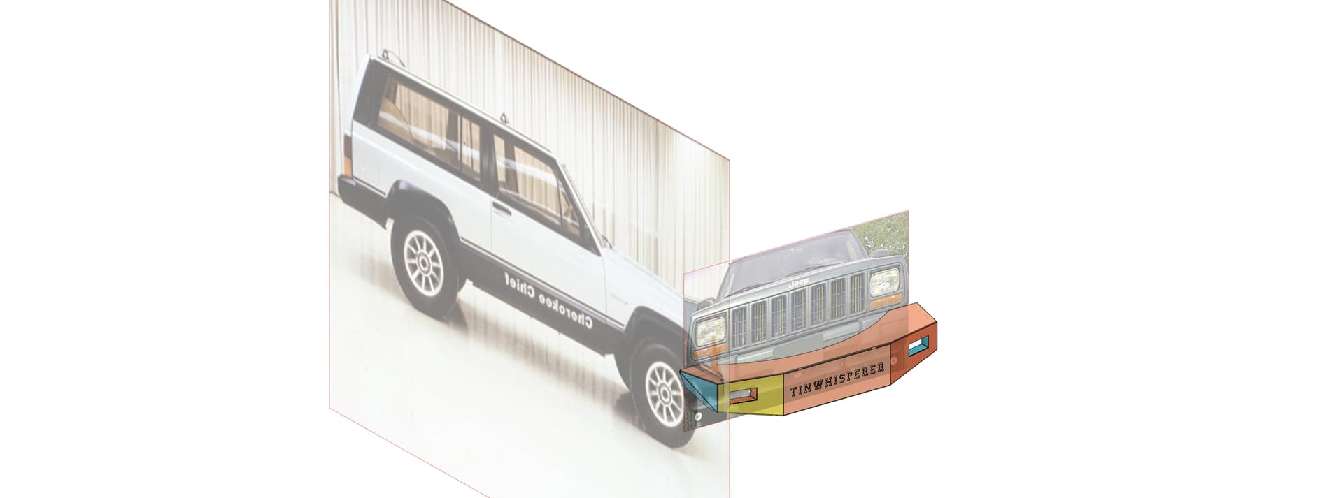
here is one I recreated for a customer, he bought a kit online of 3/16 steel but what it out of 1/4 aluminum some I reworked in fusion 360 to adjust the pieces for the aluminums thickness and bend allowances .
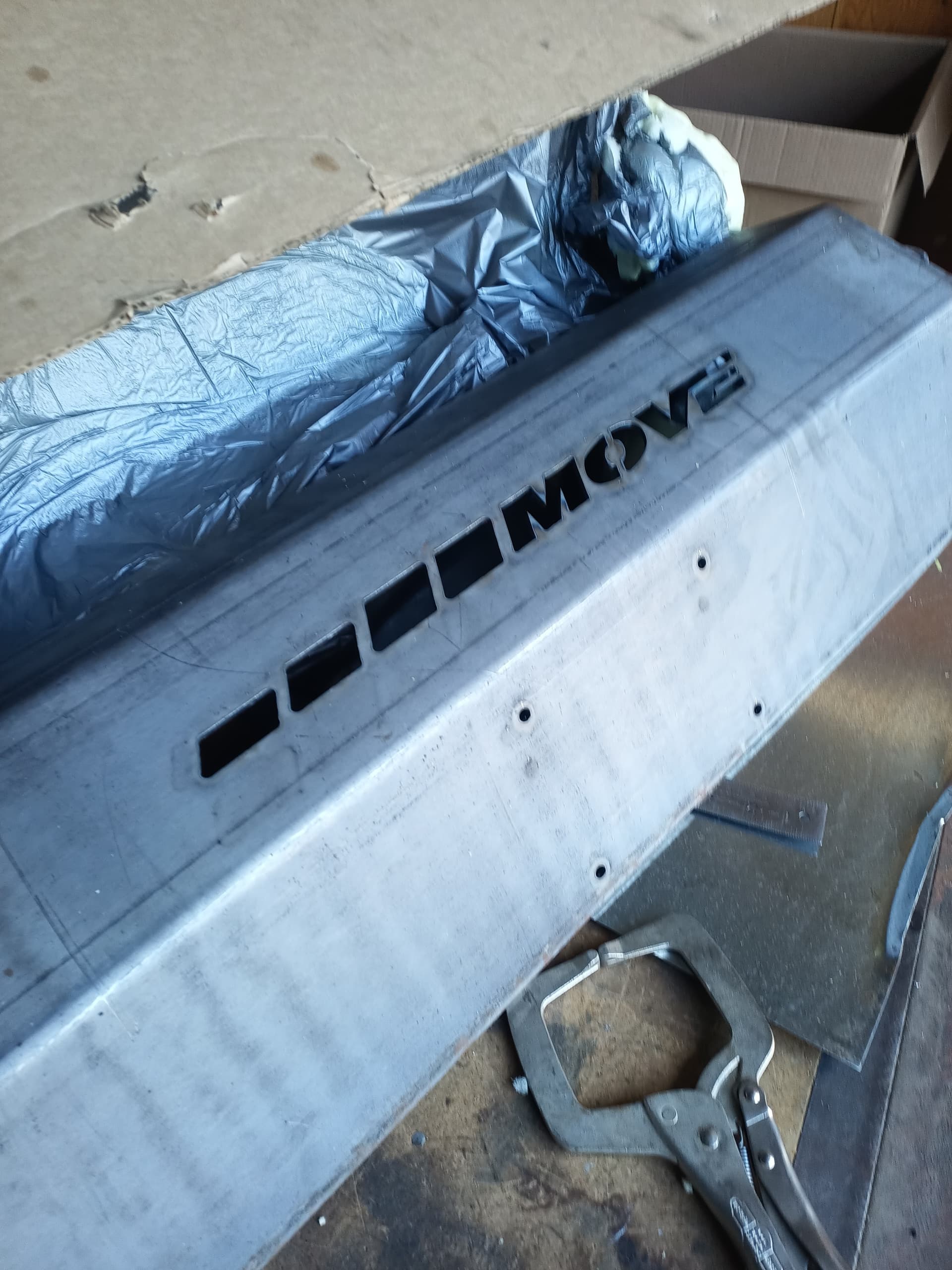
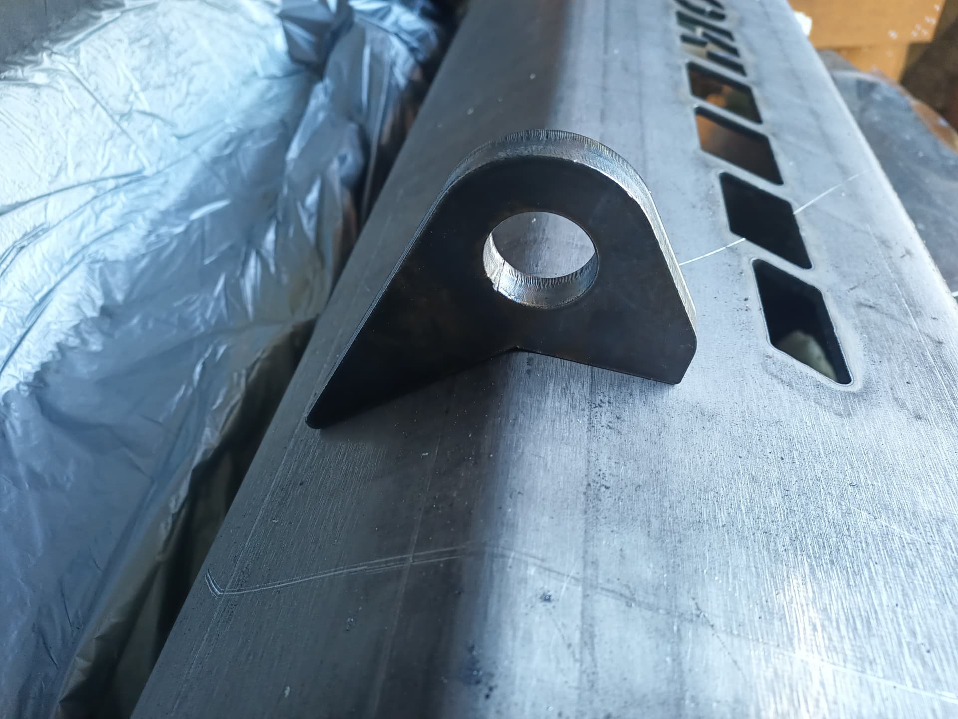
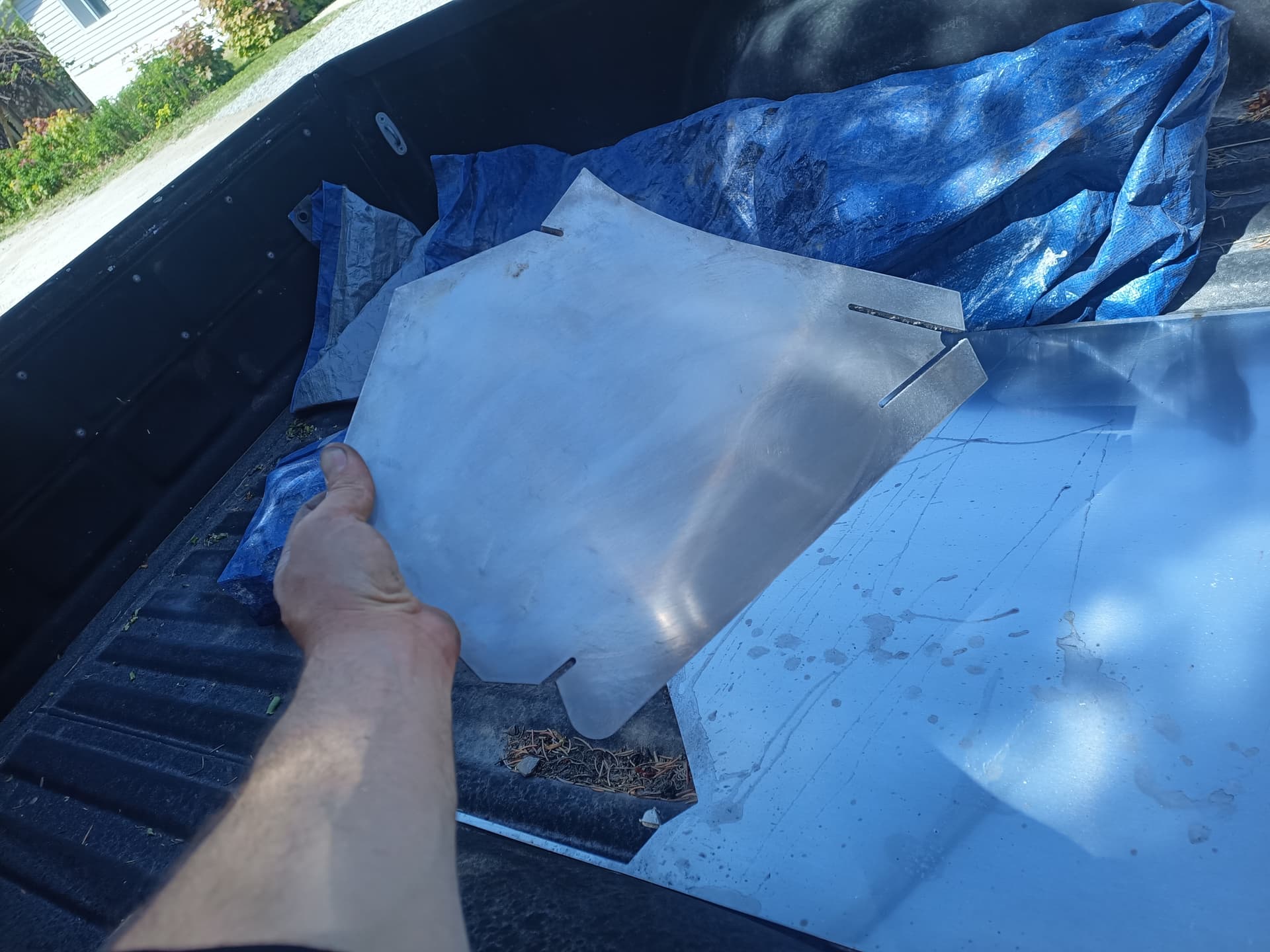
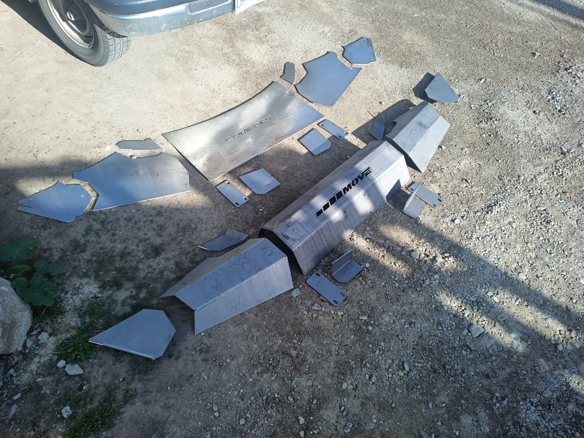
The customer assembled the components.
Is there a reason it needs to be extruded? Is that so it can calculate the extra material for the bend radius? Any other reason to extrude? Super nice bumper BTW. I can see this as being helpful for designing parts. I have been doing this the harder way it seems with my cardboard.
Thanks I think the customer was happy , really didn’t get any feedback from them.
Yes, If you are doing bends in fusion 360 it is going to need to have a thickness to apply sheet metal rules to.
Absolutely nothing wrong with the cardboard method it’s tried and true for years.
The 3D CAD programs can be a bear to use.
I’ve been pushing myself for years to try to do everything can within Fusion 360 and it’s a tough road.
I looked up that kit on amazon and now I see those are mini tab bend not tacks.
Ill see if I can figure out a video that show how to do it like its done in the kit.
That’s the method this guy uses. He makes the tabs while it’s still assembled. Seems like there should be a better way then the way he does it but it works.
What do you think @TinWhisperer

My next project id like to do a winch bumper for my 73 and 76 broncos so I have been researching bumpers.
I guess that bumper was a bad example. but the one you posted pictures of is more like what im trying to do. I have watched enough youtube videos that i halfway understand bends and how to do flanges and stuff. but i still am unclear how to have multiple parts at the same time. as always i really appreciate your responses. you are the man!
ive tried watching this video twice now. even before you posted it. and it just seems like he does a very roundabout way and its hard to follow. haha
I agree, there has to be a better way to do it. I think with al the compound bends in some of these bumpers the sheet metal workspace would be difficult. If you could do the design doing the bending might be difficult. I would like to see someone do it. Haven’t found one yet that used the sheet metal tools.
I have I different method then that video
I ll start a live stream in a few minutes 2 pm mst +/-

here is the file from the video
Sheet Metal Example multi part bumper all parts.f3d (4.5 MB)
you can use my profile picture
thank you for your time once again. it was a lot to in at once but i will for sure be referencing this video in the future.
@asummers509 When I create my Toyota bumpers I plan on 3D scanning the front end of the Toyota and importing that in Fusion 360 to design the bumper from.
I think a 3d scan will work well with the method I went over in the video
Wow and now a line of bumpers!