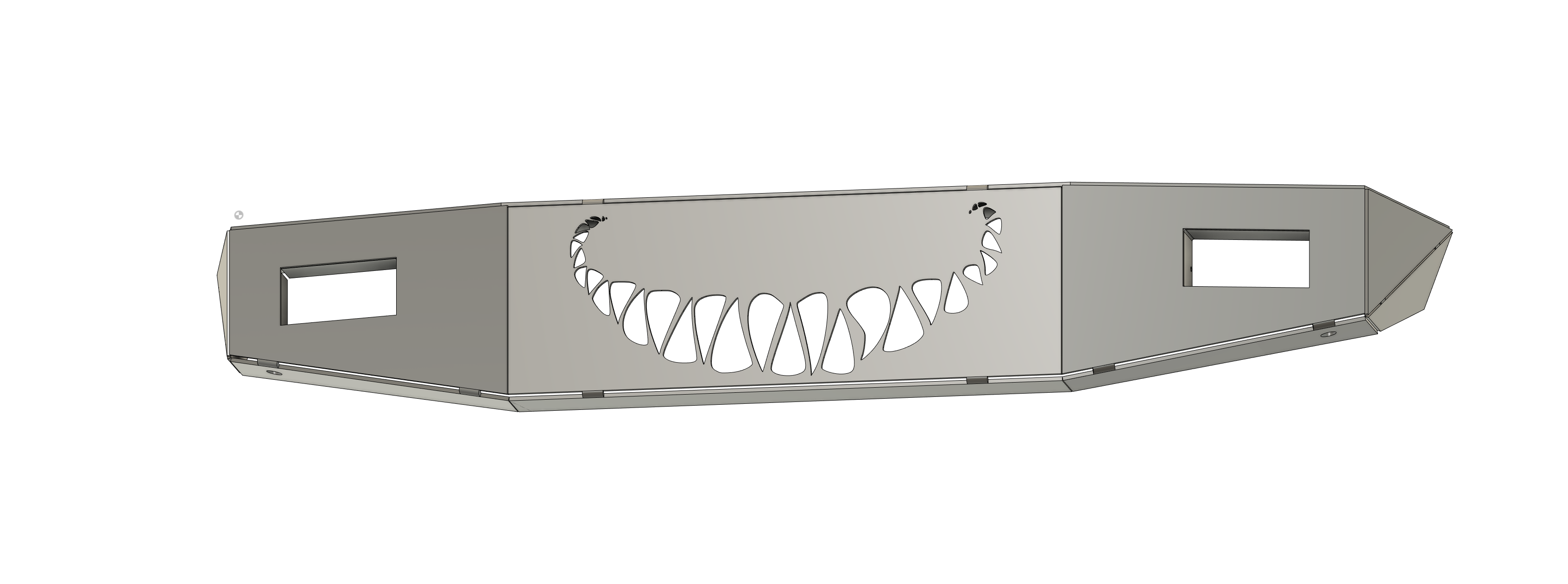
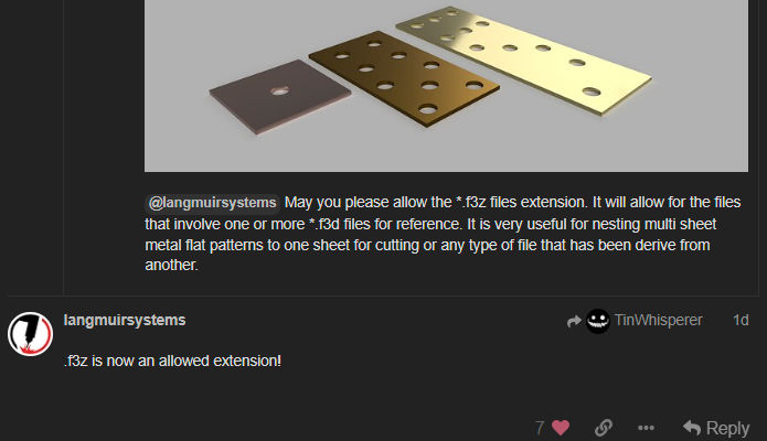
@langmuirsystems May you please allow the *.f3z files extension. It will allow for the files that involve one or more *.f3d files for reference. It is very useful for nesting multi sheet metal flat patterns to one sheet for cutting or any type of file that has been derive from another.
Honestly this has given me more than enough to think about this week. I’ve already done a similar build to the one from earlier today and gotten myself to the point of unzipping and zipping components . I struggle when I’m not actually building something to dimensions so I think I’ll go out to the jeep and get some to work with this week. I also need to set my table up this week as well. But at this point I should have plenty to keep myself busy when the time comes.
It’s a Fusion 360 file type. They’ve enabled the ability to upload Fusion design files without having to zip them first. You can just use the upload button in a message here.
Thanks for taking the time to produce these! Both videos helped simplify the sheet meatal workflow for me! And the questions I had in the first video were answered in the second. So glad I watched both before asking. I appreciate your desire to refine your content for your YouTube channel… but it really isn’t necessary. I actually really enjoy the raw nature of your twitch videos. I’d like to get through both of these again before they disappear so I can take notes. I hope you will consider putting them up on your YouTube. There is so much info in them. I should have taken notes the first time.
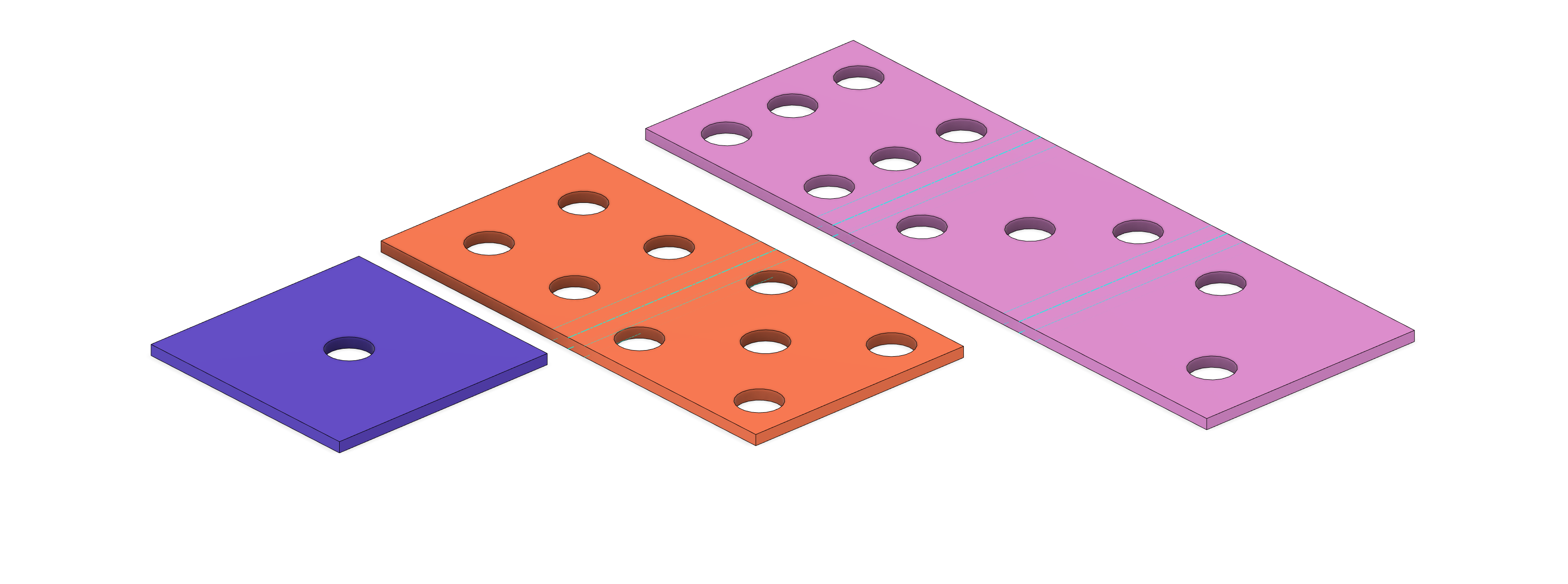
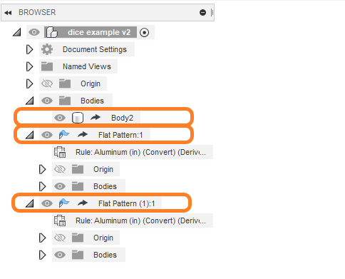
Noticed these black arrows in the browser bar, these arrows let us know that these objects were derived from another file.
I think the raw unedited live stream does make fusion feel more accessible. You get in watch the the workflow and the mistakes. Something feels relatable about content that shows everything unedited , warts and all!
All my live streams save to my hard drive so I can repost content that has value to YouTube if anyone wants.
The other issue permanent videos with Fusion 360 and my workflows are that they evolving so quickly that it make older fusion 360 videos antiquated.
@TinWhisperer you were recommended on the fb page as the sheet metal guru. I have an easy question for you. when working with a box and pan brake, witch of the 3 lines that f360 gives you in the flat pattern do you use as the mark in the brake?
@f4iryder Welcome to The Forum it’s great that you made your way here.
So what the three lines mean are the middle of the bend which is in the middle and then the two other lines are the bend extends which is the area that changes from being abandoned to being straight.
I use the center line myself on my brake .the way it’s set up it is pretty close. But all those bend allowances and everything are calculated for press brakes using a open dies. I would test to see how it works with your equipment first. The amount of material you lose should be pretty accurate. If you’re using a leaf brake or a box and pan brake you’re likely dealing with thinner materials so I would shoot for the center line on a properly setup brake.
If you do look in the sheet metal settings there is a inside outside bend allowance which could be used to really dial in a leaf brake but thin materials involved never warranted it in my case.
Relief lines or slots are always a great way of it wanting to track down the intended center.
Ideally if you want to be deadly accurate you’re using a CNC press brake.
Dang that was quick. Ive always guessed that in the past on non critical parts but i need these to be as accurate as possible. Im using 1/8 mild steel on these and ill probably be cutting reliefs. Thanks for your help, i appreciate it.