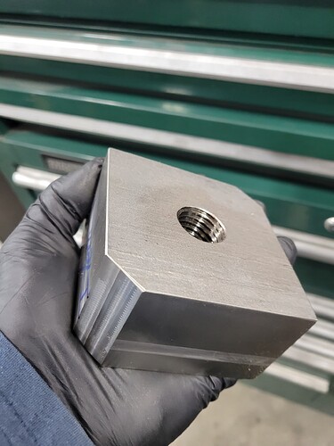
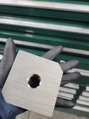
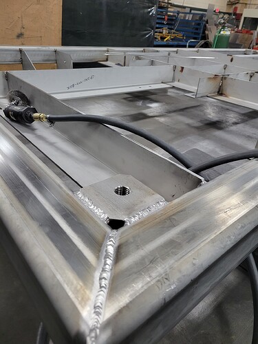
These are for a 1946 Logan lathe. 14-1/2 pressure angle I believe. There is a gear generator in Fusion that allows you to make any involute gear. My original gears are a semi-steel material, not quite sure what that is, but I made mine out of aluminum and fits my needs just fine. I made a missing 46t gear quite a few years ago out of aluminum and it’s still working fine. I made all the gears for my quick change gear box out of aluminum as well, but the compound gears kept slipping or breaking when I tried to join them together.
Looks great! Would you mind if I asked you a few questions on your threading?
No problem. I’ll do my best. I’m still learning the threading process. I have successfully done several projects with larger threads.
Thanks,
Im working with the assumption these threads were threadmilled correct? Im fine with modeling the thread ( in fusion 360), creating the tool path, ect. My question comes in regarding adjusting the fit of the threads. On the machines im use to running, mori seiki production machines, we comp our tools big and work up to the proper fit using a tool table. Seeing how cut control doesnt have this option, i assume to adjust the tool diameter/radius and thus the fit of the threads id have to change the tool dia info in fusion then repost that tool path, sound correct? I know im probably overthinking this.
Thanks.
I bring in the offset in several steps.
So your minor diameter less your max diameter. I would target 50% of the difference. But, bring in the tool in steps while checking fit at each program end.
I would say once I get some offset data vs the thread size. I would get a little bolder on the settings.
I would hate to screw up a part at the end trying to thread it.
Exactly the way i do it now. If its good enough for aerospace work its good enough for me.
Thanks, much appreciated.
You got it. Anything I can do let me know.
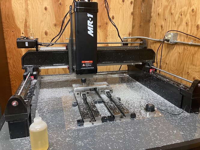
testing few more operations for my MR-1.
I tried a 2D pocket/boring operation and then a chamfer on my previously cut test part.
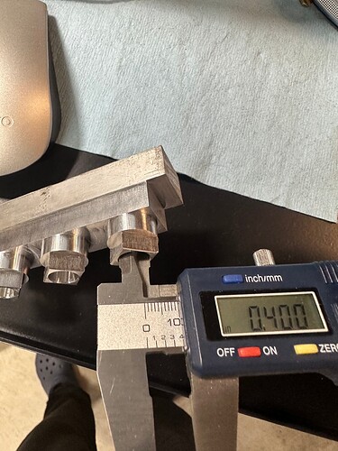
I used the probe to get a new origin on the previously cut part and then run the 2D pocket with roughing depths and a second 2D pocket full depth to remove 3/1000” left. I aimed at 0.4” hole.
I am impressed with the results I got.
You can see the link on the ops with more detailed description on youtube:
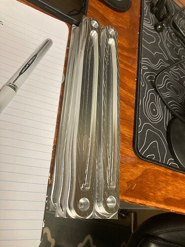
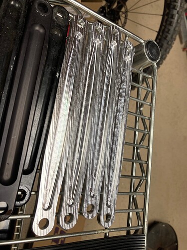
First operation on some jacobs ladder straps. 1/4” .03R endmill and a 1/4” chamfer mill. I’m happy so far. Still haven’t made my enclosure, so no flood coolant. Not an issue with simple stuff like these.
Looks great, Thanks for sharing!!
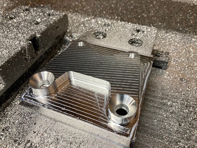
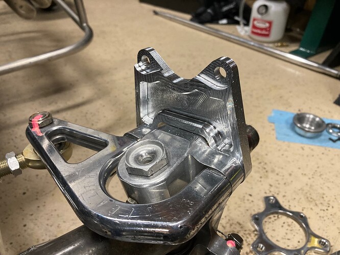
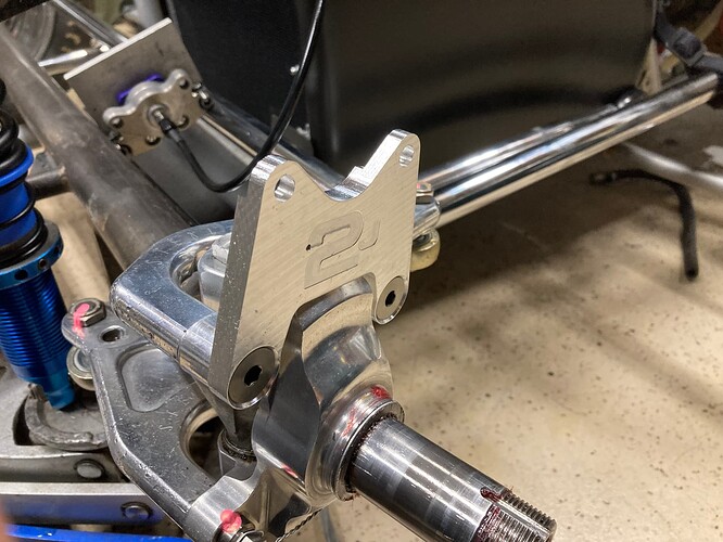
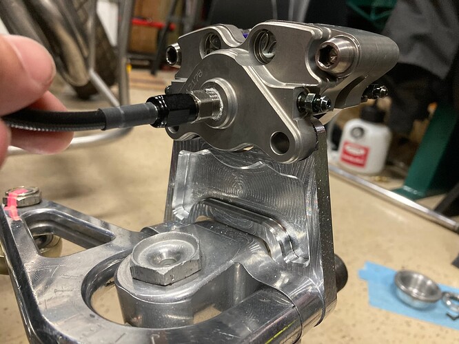
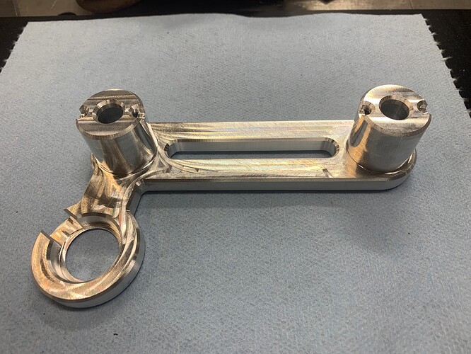
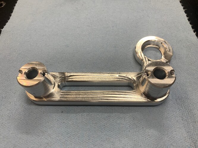
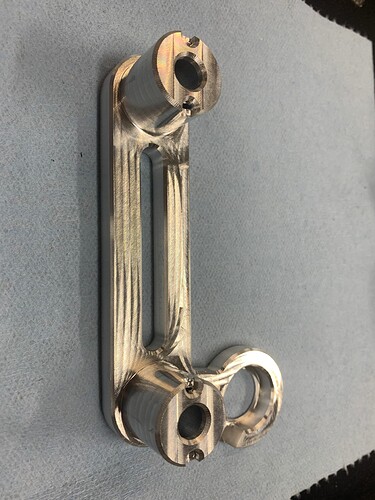
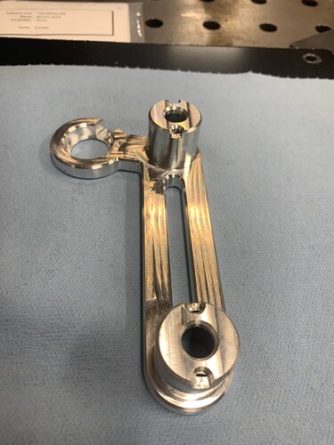
Finished the straps and started on a brake caliper mount. 1/4 bull endmill getting a workout, still no coolant.
Looking forward to more of your projects.
The caliper bracket is awesome. Without the enclosure it must be a god awful mess?
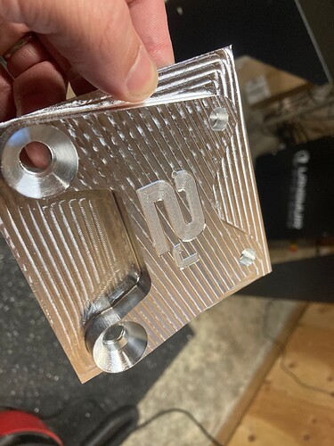
Thanks, the other side will have a pocket and a couple details, it will be a nice piece. Chips are everywhere, but after the wait they are a welcome sight.
Side note, don’t trust the tool setter without checking that z is where it’s supposed to be. Buried a 2mm ball mill going for the afterthought engraving. No big deal, glad I learned on this and not a 1/2 endmill. Gotta remember this is a hobby mill, not a haas.
do you know what went wrong with the tool setter?
I did that with a chamfer tool and put it all the way through a 3/4” piece of aluminum. It was my own fault though, forgot to set the new Z zero.
Not sure what happened yet. I’d been through probably ten previous tool changes the same method without error.
I’ve had this happen repeatedly. The offset error is often [exactly] 0.5" or 1" but I’ve seen it closer to 1.5". I am hoping that the cut control 22.1.1 firmware will fix this. I did the firmware update today and wasn’t able to trigger the error after about 5 repeated toolsettings. Fingers crossed…
Looking great. Glad your finally enjoying it


