I’ve spent the last day documenting and testing procedures that worked for me to cut a pattern in excess of the Crossfire Pro 32x48 limitations. Below is my guide and pictures of the example that I have used.
This would al be even easier if FireControl allowed you to move the torch head when the g-code program hits a pause, but I found that I could only do so when the program was stopped.
Please post if you have any better suggested ways to do this or any improvements.
Indexing Guide for Crossfire Pro
Physical Setup – To do this accurately, you should have a straight Y-axis guide on your machine and check to make sure your X-axis and Y-axis are at 90 degrees (cut a 12x12 piece and check the corners for square).
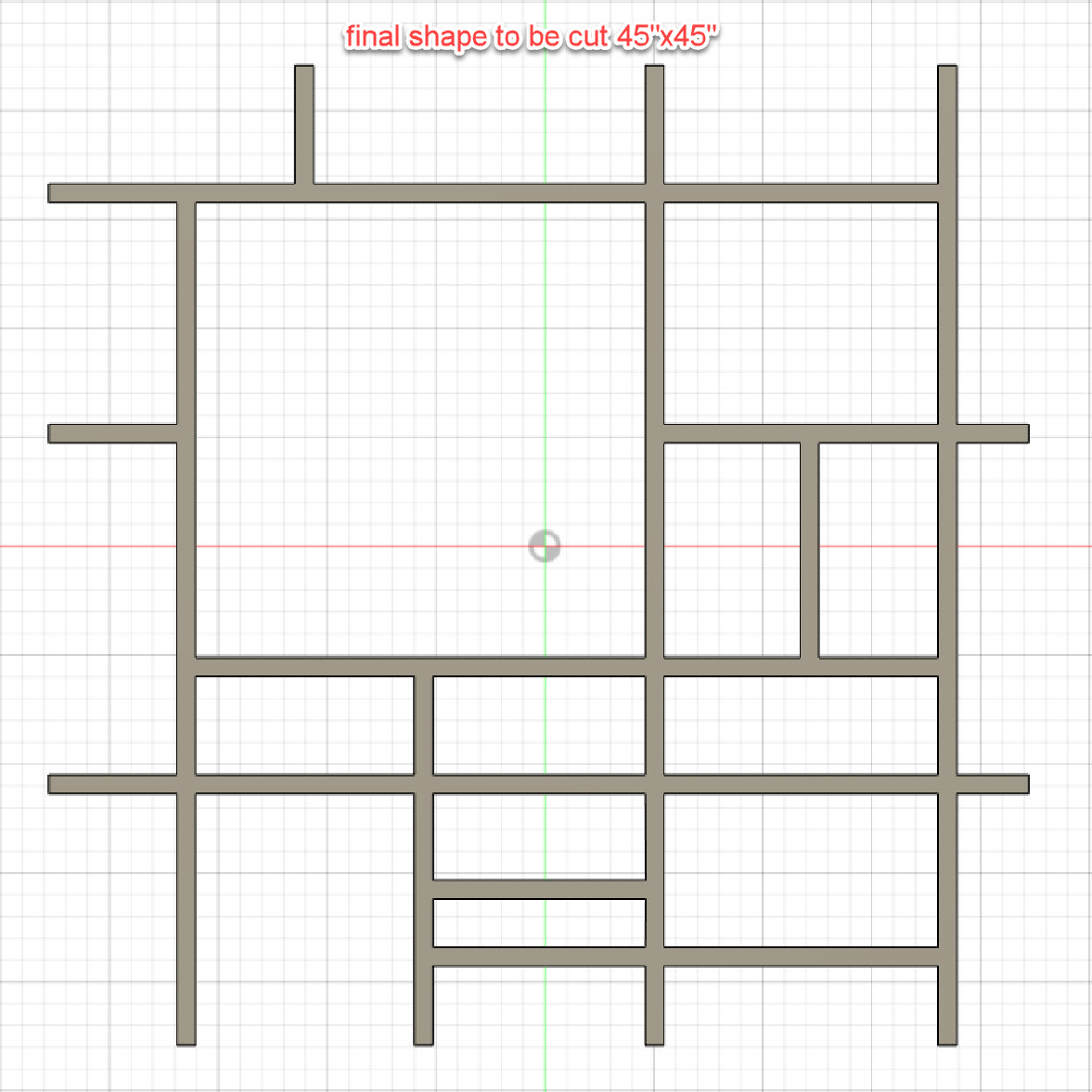
Example Parameters - I am using a Mondrian shape pattern 45x45 and assuming two sections (a lower half and an upper half) to be cut. You could in theory expand this to a larger height pattern of up to 60 inches, but after that the WCS orientation point could not be kept the same.
Design Mode
- Create full design in Fusion 360
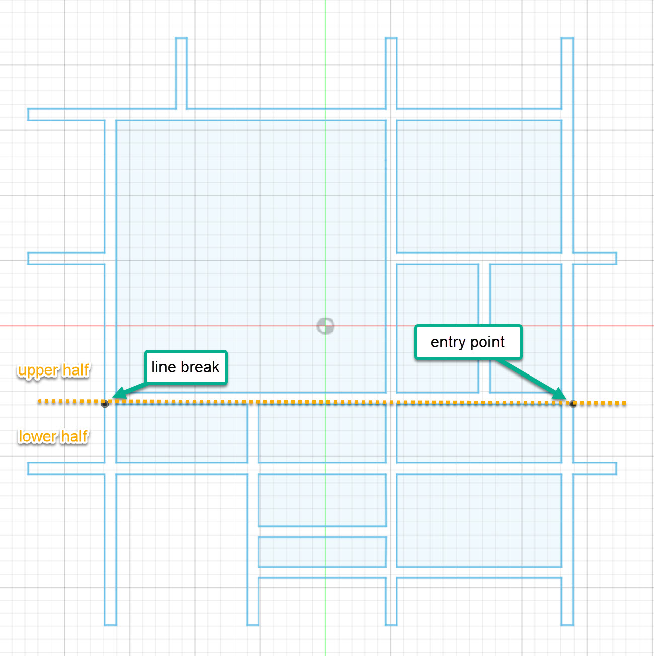
- Decide lower half to be cut so that each section of the design will fit in the cut area (32x48).
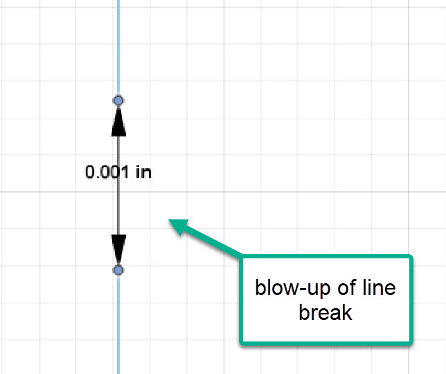
- Create small line breaks (mine are .001”) at the upper right corner and the upper left corner of the lower half. I did this by adding two sketch points very close together on the line, then deleting the line and redrawing it with the small break in between. You will no longer have a solid body when this is done and that is necessary so that you can have a cut break in the g-code and select individual line geometry order.
- Finish sketch
Manufacture Mode
- Setup -
a. Machine - Langmuir Crossfire Pro
b. WCS - Model orientation … IMPORTANT
c. Model box point … IMPORTANT
d. Box point – select as central a point as you can … IMPORTANT
e. Use Fusion 360 “I” measure shortcut feature to get distance from central point to (1) the lower model edge and (2) the left model edge. Record these distances for future use below. - Cutting -
a. Tool - Select your tool.
b. Geometry - Select cut contours paths in order of desired pattern.
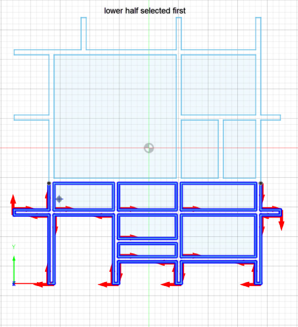
c. First select the lower paths and then the upper paths.
d. Each exterior segment has to be selected individually if it is not fully bounded.
e. Make sure cut is in correct direction and lead-in/out is on proper side. - Passes –
a. Preserve cut order … IMPORTANT
b. Choose other options you want. I slow down for sharp corners and circles. - Linking –
a. Choose options you want for the cuts you need. - Post Process -
a. Post to “indexfile1.nc” (or name of your choice).
Physical Setup And FireControl Mode
- Mark indexing points on Y-axis guide and on two spots 1 to 30 inches (XX inches) apart on your metal sheet. The distance may vary for your particular design needs depending how far you need to slide the metal sheet to fit your design. In my example I used 16 inches.
- Open Fire Control and load “indexfile1.nc”.
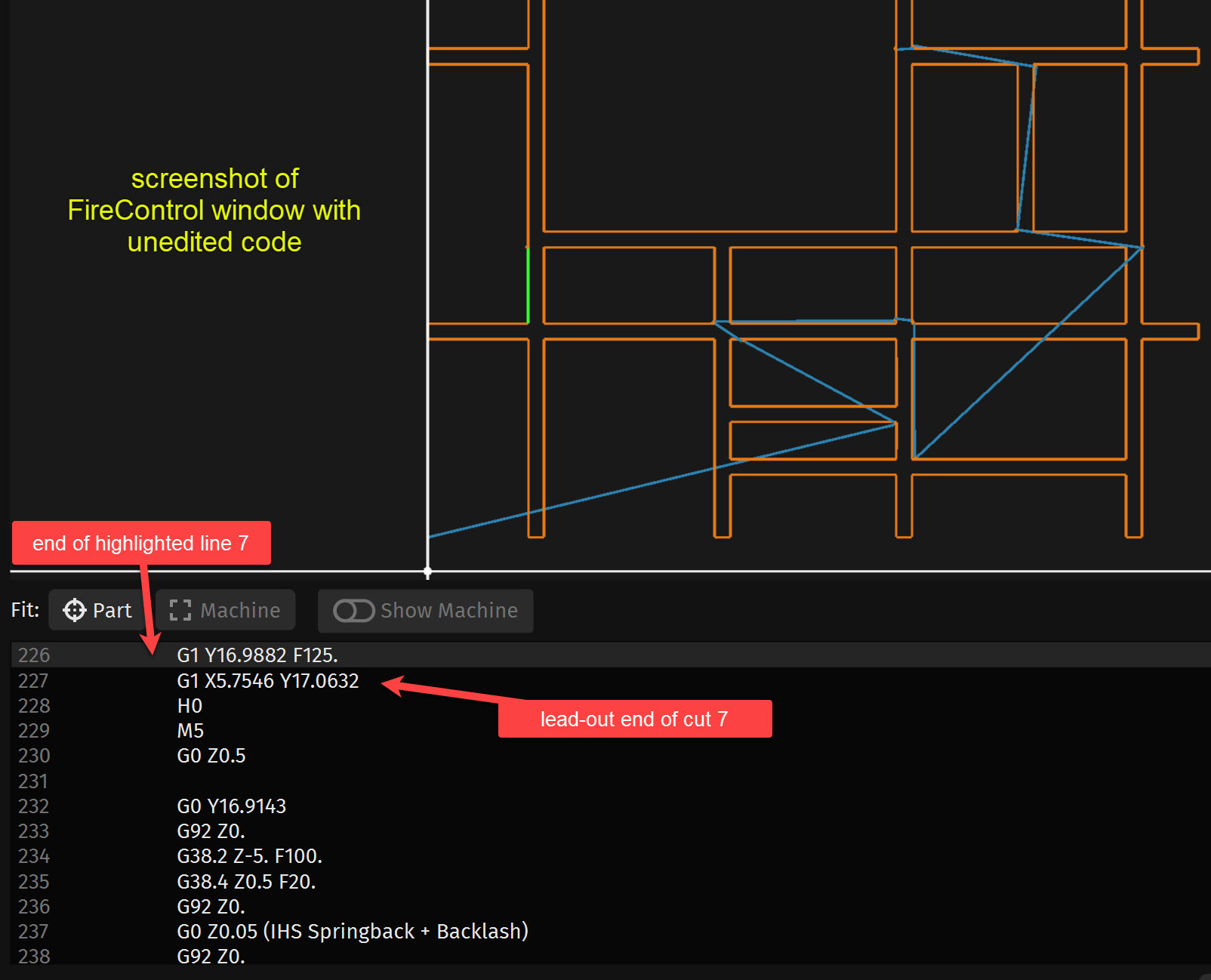
a. Click on the path just before you want to create the pause and note the line number in the g-code display.
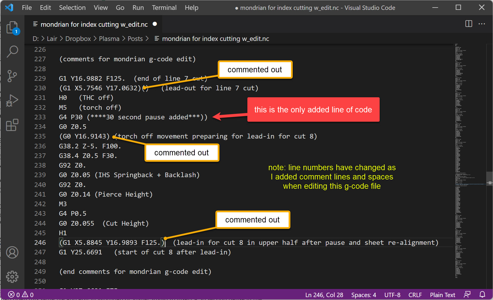
b. Then open this same file and edit in Wordpad or Visual Studio to insert a 30 second pause in the .nc file somewhere after last lower half cut path you identified above and beginning of the cut to be continued. The g-code command for this pause is “G4 P30”.
c. Delete all G1 line of code between breaks. This removes lead-in’s and lead-out’s which seem to mess with cut re-alignment. (I have commented out the lines in my example.)
d. Delete all G0 Yxxx lines of code between breaks which also seems to cause alignment issues.
e. Save this edited .nc file as “indexfile2.nc”. (I have commented out the lines in my example.) - Set up your metal sheet aligned with the Y-axis guide and slide it so the lower left corner is at a spot that can be near the finished lower left corner of the pattern.
- Position the torch head in the center area of the sheet where it will just reach. Use your measurements from Manufacture Mode 1(e) above to get a correct placement. Then “ZERO ALL AXES”…IMPORTANT. Do NOT ever uses the “SET PROGRAM ORIGIN” during this entire process.
- Do a “DRY RUN” for THE lower half. Re-adjust origin if needed and again select “ZERO ALL AXES”. Repeat dry run. Proceed is correct results occur.
- Now cut the lower half for real. STOP and RESET program at added 30 second pause. Do not “ZERO ALL AXES” yet.
- Select “GO TO WORK ZERO” which should take your torch head to where it was when you began the lower half cut.
- Slide sheet along Y-axis edge guide XX inches that you decided in item one above.
- Move cut head the same XX inches ONLY on the -Y axis so that torch is closer to the bottom of the water table. If you select the FireControl option to move in one-inch increments, that can be done easily.
- Reset “ZERO ALL AXES” at this new location.
- Re-load edited “indexfile2.nc”.
- Select the beginning upper half path line from the pattern display in FireControl. Click the highlighted g-code line below the display and choose “RUN FROM LINE”. Then click as directed on the screen to GENERATE the upper half program to be cut. It is critical that the WCS coordinate system point is the same as when the lower half was cut.
- Do a dry run first to check correctness of pattern. If alignment is correct, proceed.
- Now cut the upper half for real.
Pattern to be cut 45x45
Decided entry and end of lower half points where breaks were created
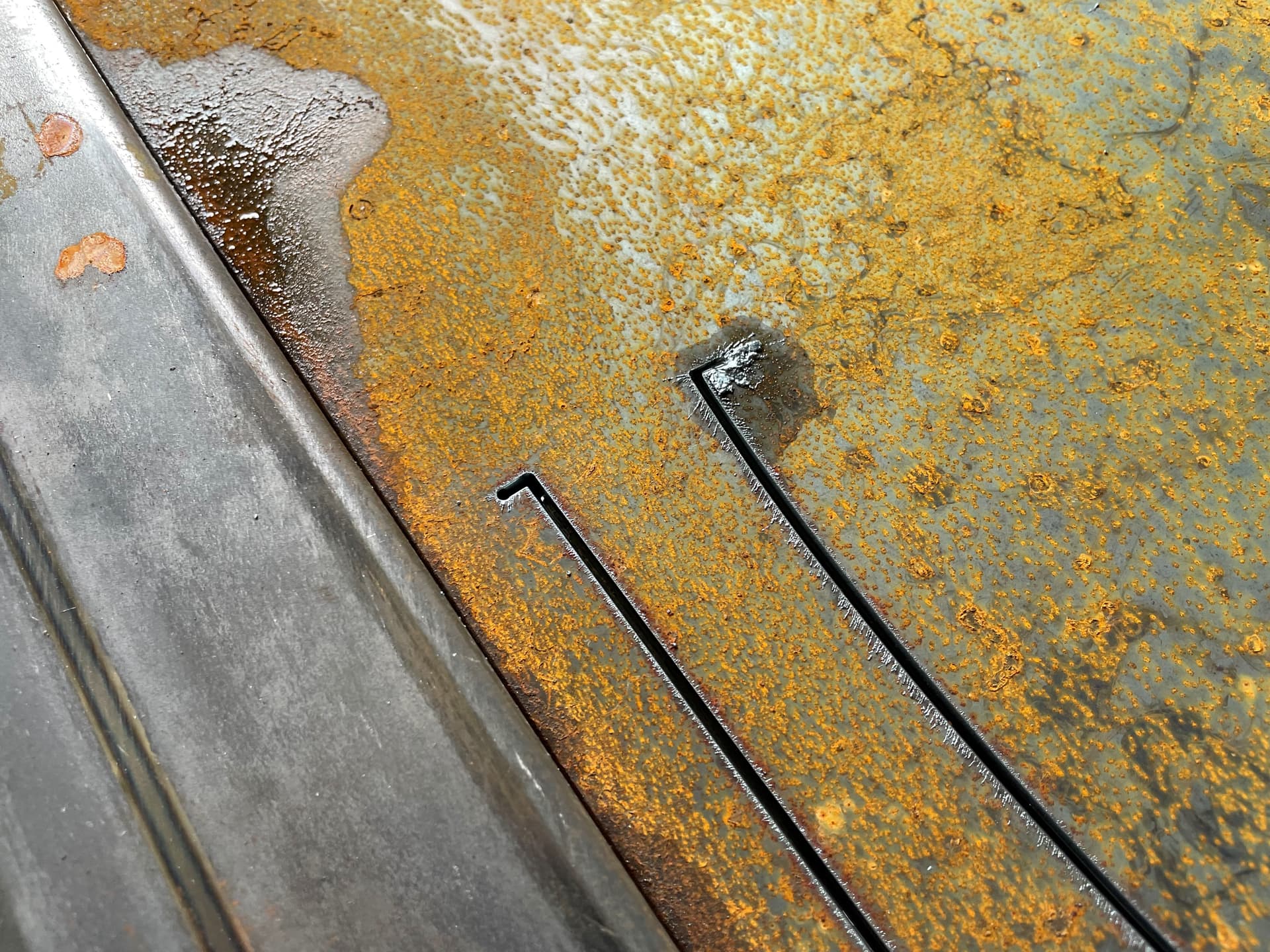
Tiny breaks created
Order that I decided to make the cuts
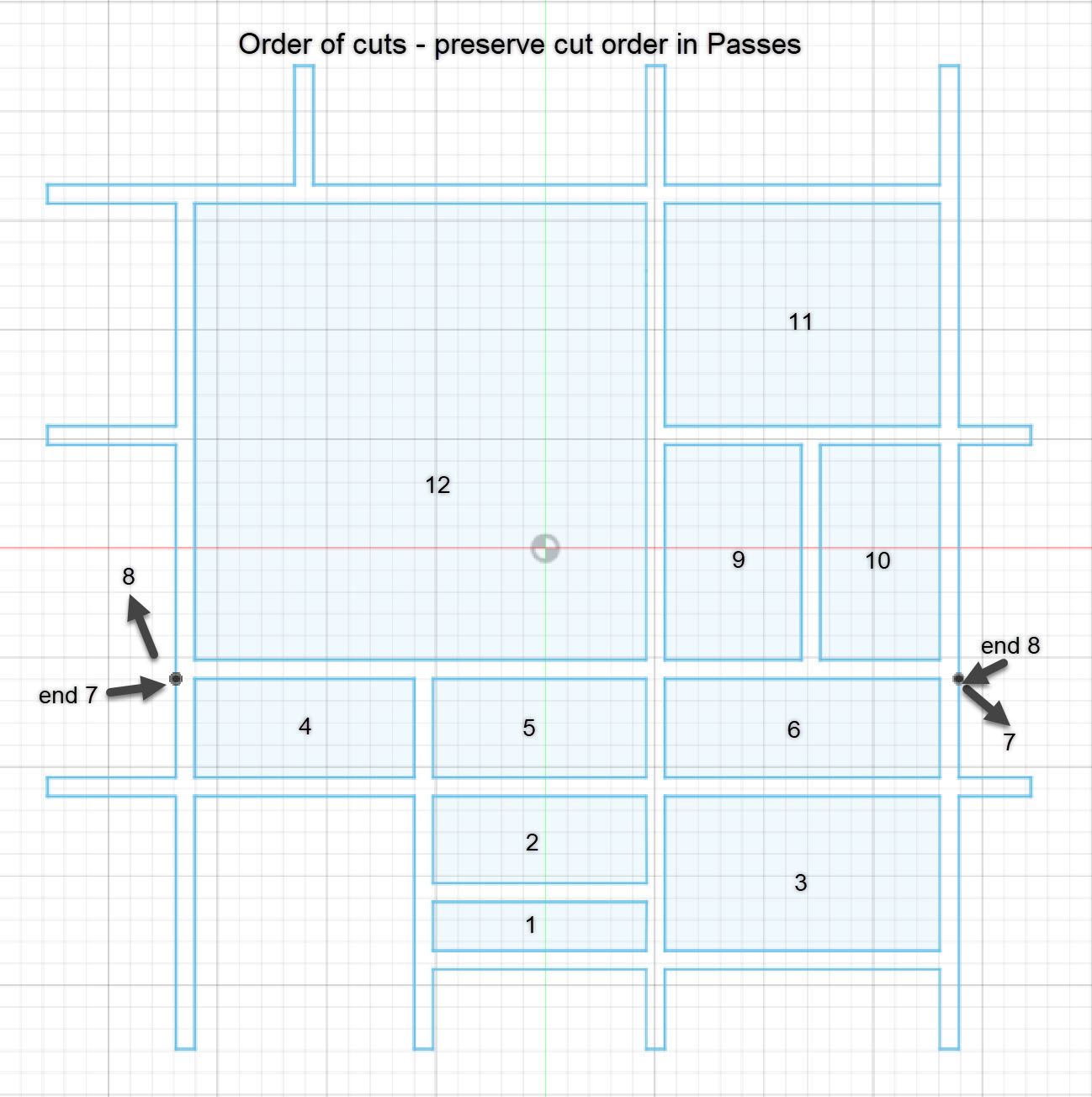
Lower half cuts assigned first
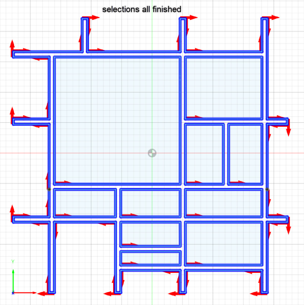
All cuts selected
Screenshot of un-edited code
Screenshot of edited code
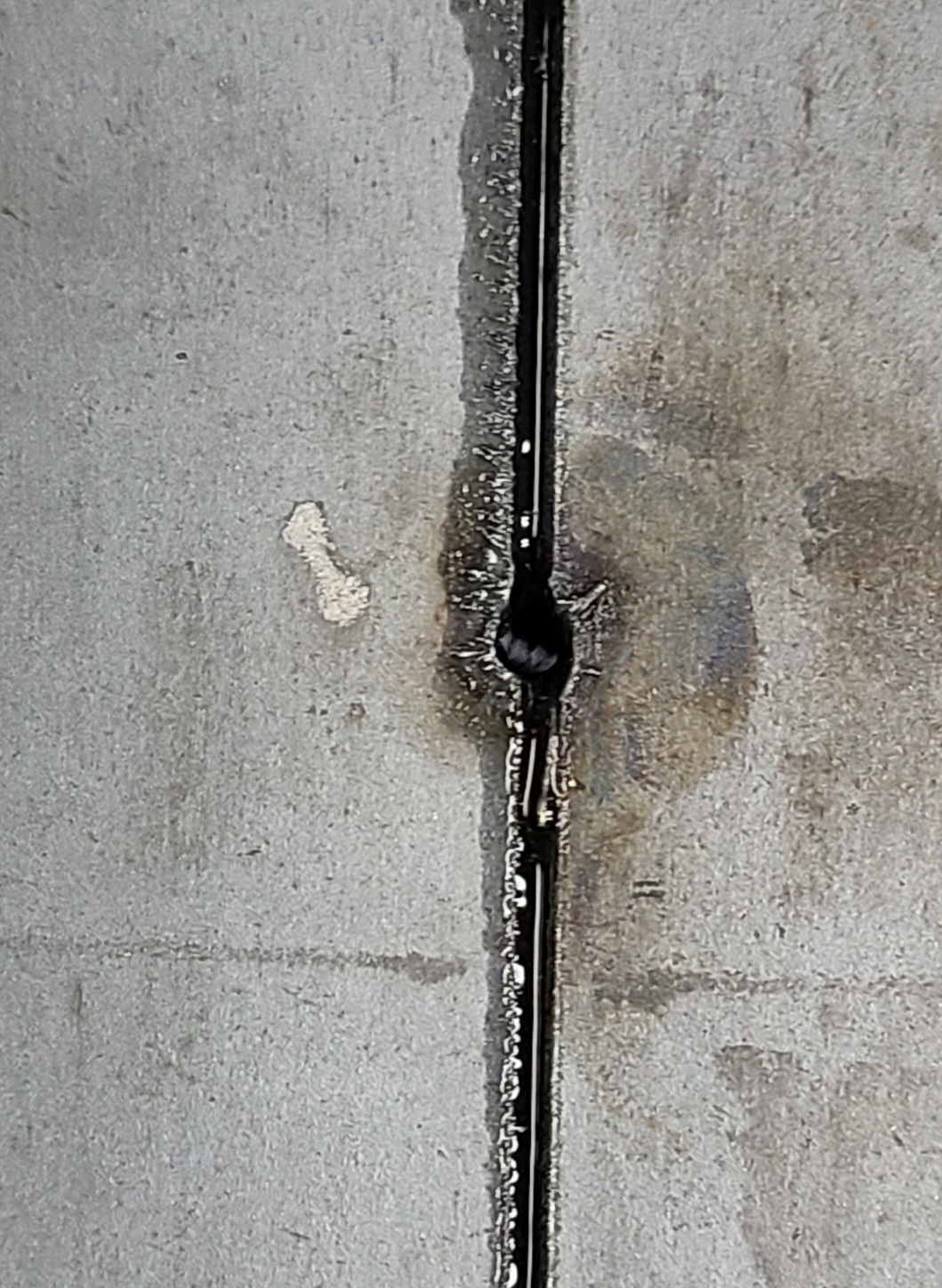
Actual transition point from end of cut 7 and beginning of cut 8