If you’re still using the free version of Loom you could go with the paid upgrade or move over to OBS. That’s open source, free and not time limited. You can create a variety of formats and then toss them up to YT.
1 Like
Hey I just now saw the video, very helpful. For me personally I think a video showing the process of saving to a pdf, and the process of sending it to the actual table
1 Like
I recommend you fight thru confusion, it has the cam software included. Other systems may be easier to model in but you’ll have to convert to a transfer format to import them into your cam software.
For driving your plasma cutter you only need to learn the sketches part of confusion. Sketches are a free form method of modeling. Example you enter 4 lines for a square, don’t have to be “square”, the next step is constraining them. Constraints force geometry to be a fixed length, perpendicular or parallel etc.
The good thing about confusion is there are many tutorials on YouTube for every level of its use. Some of the guys doing them will bore you to tears or generally piss you off, but keep going. It will all start to make sense.
I’m in El Cajon, CA. If you’re local let me know, we can work something out to get you going. I feel your frustration, I work with large multi-axis milling machines daily, my little 2 axis crossfire had some issues that pissed me off, some guys helped me thru those issues. I’d be glad to pay it forward.
4 Likes
@TinWhisperer I just had time to watch the video you made and it is great!
you asked what should you do next, well how about the basics for us?
what the left side panel all means, do we trash a sketch if we have to make another setup, how do we make multiple setups and why, how to edit a sketch after setup…
I can draw a piece like you did and get it to cut BUT i do not know the basics of the program. the how to’s and why? thanks
1 Like
.
@ImaStreetRodder @jamesdhatch
posted a new video here that touches on these concerns
Thank you for the content suggestions.
1 Like
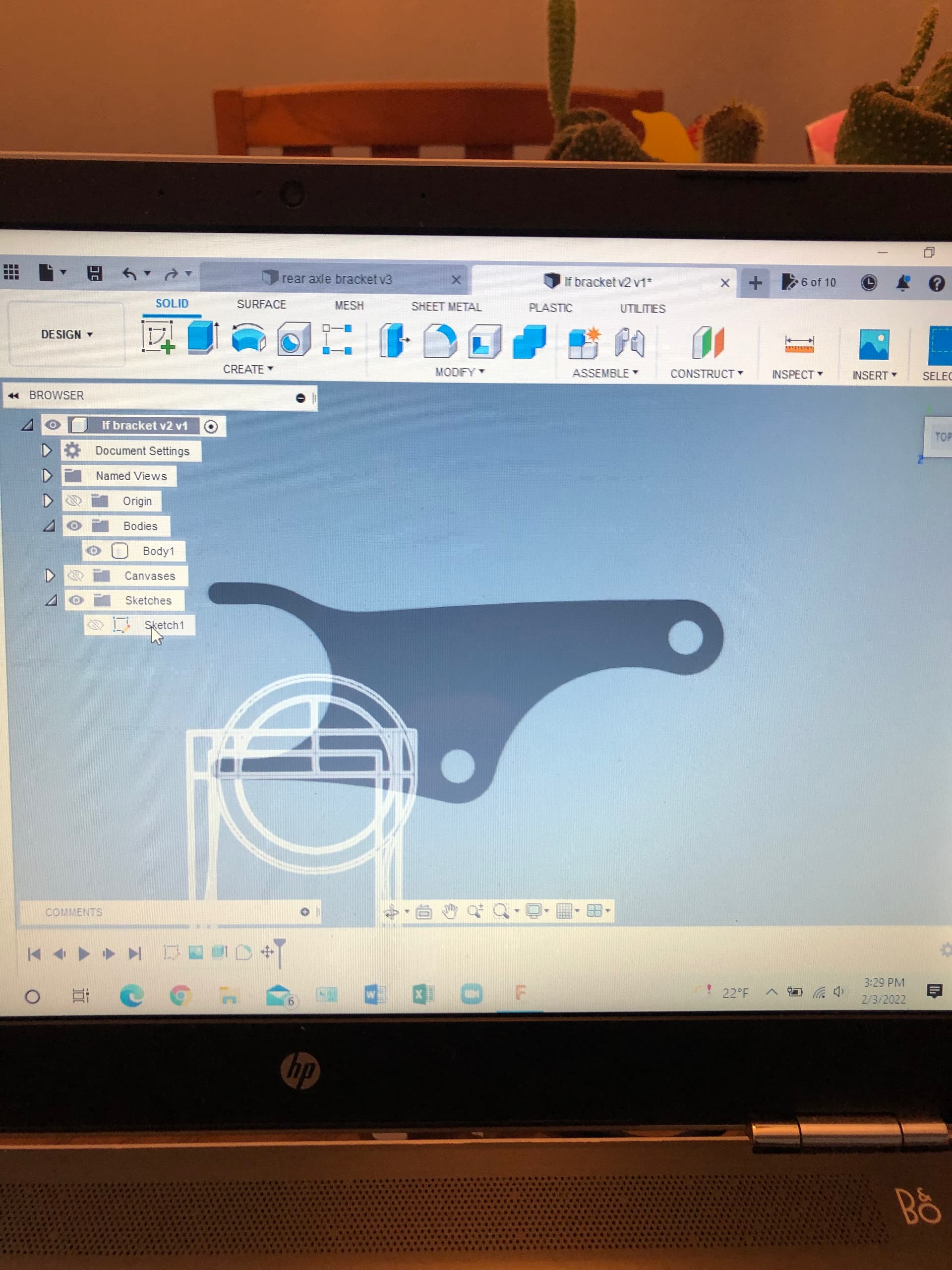
I’d like to chime in, if I may. On your drawing of your bracket, I would turn it clockwise upside down and make the bottom of the two ‘horns’ Datum A. The left ‘horn’ with the straightest side will be Datum B. Then you can reference your dimensions from these two Datum’s and get a more accurate and easier to dimension part. On the 4 holes plate example, the importance of the spacing on the 4 holes determined how you dimension them. If you just go from the sides as shown the plate may not fit of the plates is 1/8” or so over size. If you dimension the 2nd set of holes from the centerline of the first two overall plate size won’t affect the fit. In your part the center of the large dia. cutout controls the action of the other two holes in this bracket’s application. The centerlines of the part it side radii can also be referenced off of A and B. Now, I’m not helping you with getting this from paper or screen to actual part. I get that.
On Fusion360 we’re you at least able to get to the simulation portion of your job? If you get to work then you need to have the proper handshake program for fusion to get the part G-Code to your Crossfire machine. I guess, in short, breakdown the process to see what is hanging you up.
Also, try drawing your part on a 2D cad and then import that into Fusion360, extrude it and work from there. Lots of helpful videos out there for us to learn on.
I hope this sort of helps.
I share your feelings for 360. I use LibreCAD to draw up my part and get a dxf file. It is free and very simple. Then I use sheetcam to create a tap file which is then ready to load into your table. Sheetcam is also free for up to a certain number of gcode.
Hello @TinWhisperer i have to say thanks so much for the videos! You a natural at them! I was about to give up on fusion and I think I will continue to learn it! Thanks again, joe
1 Like
I want a " TinWhisperer" decal for my shop also. You’re a Fusion 360 saint pal…A born teacher.
1 Like
I want to say that sometimes you just need to keep trying and trying.
You will not forget when you finally get it to do what you want.
Learning the hard way, I guess.
I have used Bobcad, ProE, cadkey, Onecnc, and each have their own quirks.
The order you pick the points for a sweep, the plane you draw on, there is much to learn. Tutorials are your friend .
As I told a frustrated coworker, you are feeling that way because you expect it to work right the first time. Expect to struggle and your mindset will be different.
.
1 Like
How do you download it to Langmuir site
if you are wanting to post a picture from your computer to the forum…you use the little box with up arrow…
then find the picture or file …
Hey good afternoon, well I’ve been doing lots of video watching and talking with Allcut (David) which has been a huge help. So anyway I thought I’d burn some scrape up and make this peice that you were so kind to draw for me except when I send it to SheetCam it shows all the over lays. How do I get rid of those so I can do my layers and send it to burn?
Did I ever send you a dxf?
What are you importing into sheet cam?
Depending on how you got a DXF from Fusion 360. My contain construction lines and other information.
I’ll see if I can export a clean DXF from the f3d file I have.
I’m not sure what sheetCAM has as DFX importer. But a lot of the times when you’re importing a DXF it will give you choices of which layers you would like to have or not during the import process.
I’d appreciate it. This was what I was working from
So did you export your own dxf from that f3d and then inserted into sheetCAM?
I downloaded the file as you saved it and then saved as a dxf which I sent to sheetcam
Imastreetrodder Bracket Forums.dxf (5.9 KB)