Crossfire Gets An Upgrade - Floating Z Axis Installed

@Kentucky13 had a few questions about setting up mach 3 and fusion for z axis. I’ll post here to help everyone out.

Setting up the z axis in mach 3.

First set your output pins under config, ports and pins, motor outputs. Z axis will be step pin 6 and dir pin 7 with step port 1 and dir port 1(Only if you follow the breakout board pins from bottom to top for the motor outputs). Make sure there is a green check mark next to z axis to enable the motor. Click apply then click ok.

Click config. Save settings.

Next we will want to configure the motor. Click config then motor tuning. The steps per will vary depending on how your z axis is setup, the distance traveled per revolution and the micro stepping on the stepper driver. This is easily figured by doing some math. Most steppers are 1.8 degree per step with 200 steps per revolution. There are a few ways to get to the same answer but here was my math.

*= degree
Stepper driver set to 8 micro step.

1.8* per step/8 micro step = .225* per step
360*/.225* per step = 1600 steps per revolution

My z axis has a 1605 ball screw which is 16 mm diam and 5 mm travel per revolution = .19685 inches per revolution

1 in travel / .19686 inches per revolution = 5.08001 revolution per inch of travel

5.08001 revolutions per inch x 1600 steps per revolution = 8128.016 steps per inch

Back to mach 3 motor tuning. I set steps per to 8128.016. There really is no need to have your z axis travel anything faster then 100 ipm so this is what I set my velocity to, 100 ipm. I kept the acceleration rate the same as both x and y axis at 40 inches per sec. If you have a heavy z axis and the motor stalls as soon as it moves, you may need to lower this number until it doesn’t stall. Step pulse is at 2 and dir pulse is at 2. Click save axis setting. Click ok. Click config. Click save settings.

Go to config, slave axis and make sure all are set to none. Click ok. Click config. Click save settings.

Next go to config. Homing/limits. Set the soft limit for the z axis to a little more then your total travel on the z axis. If the travel is 4 in set soft max to 4.25 and soft min to -.25. Depending on how your z axis is set up make sure green check mark is showing under the reversed column. Click ok. Click config. Click save settings.

Next go to config, system hotkeys. Set the z++ and z-- to whatever buttons you want to move the z axis with. I used page up for z++ and page down for z–. Click ok, click config,click save settings.

This should be it for mach 3. Restart mach 3 and see if you have control over the z axis.

In fusion there are a few settings you will have to change. During cut profile setup and post process setup.

Draw your part then go to manufacture tab. Click new setup as you normal would. Under the setup tab make sure you select the top of the material at your usual location for the coordinates, only if it is extruded. Next go to the stock tab and make sure you have stock top offset set to 0. Set your other parameters and click ok.

Next select the 2d cut profile as you normally would and select your tool. Select your contour. Then under the heights tab set your heights. Read thru what each height does. You can do this by hovering over the drop down menu. For initial testing I set clearance to 1 in. Retract to 1 in. Top height is going to be your tip to work distance. .06, .1, .120 whatever you want it to be, this is essentially your shim thickness. Set everything else normally.

Now let’s go to post process like normal. Set your pierce height to what you want it to be minus your top height from the previous step. Not too sure why, but it adds this height to your top height. So if your top height is .06 and your pierce height is .1 the actual pierce height will be .16. If you have a probing switch set it up under probe and probe offset. Scroll down and make sure you have use z axis to yes. Side note, you will have to set pierce height and probe offset everytime. Click post.

Back to mach 3. Open your g code and set your home 0,0 location. Bring down the torch to just touch the top of the material (if you don’t have a probe feature). Click ref all home. This will set everything to zero. Start your g code. Torch should travel to retract height and go to first spot to cut. It will drop to pierce height, start the torch and dwell for your pierce delay time, then it will drop to top height and start the profile cut. After the cut it will go back up to retract height and move to the next spot. Once done with all the cutting the z axis will move to clearance height.

Side note. If you want to keep the torch down use the keep nozzle down feature in fusion. Otherwise don’t use it. Since you have a z axis you really don’t need to use that option anymore.

I think that is all. Anymore questions just ask.
6 Likes

Here is some more info some have requested on the items used in the build.

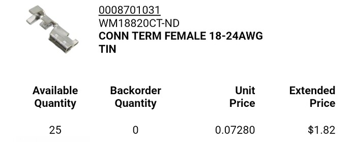
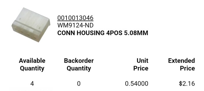
These are the breakout board connectors I used.
Ordered mine from digi key. These are the exact fit items which makes for a tight fit when installing them. The connectors already on the board have a bigger opening which makes them easier to insert on to the pins.

3 Likes

Great job on the z axis upgrade. I am very new to cnc. But I would really like to install a basic z axis to my Cross fire do I need a motor controller for the z axis stepper? Also what is the voltage on the z axis out put pins? Thanks for any information

1 Like

Bearing in mind I’m just a clueless idiot following along when the the thread,

You do need a means of controlling the Z axis however Langmuir did have the foresight to include some provisions on their break out board for a z axis.

Thank you. Most of the questions you would have is covered in the write up.

You will need another tb6600 stepper driver for the z axis motor.

I’m not sure what you mean by the voltage on the z axis output pins. The pins on the breakout board or pins on the driver?

2 Likes

There are 4 motor outputs X,Y,Z and A. 4 inputs and 4 outputs. All of which can be made functional.

2 Likes

What does A axis do?

You can do a few things with an A axis.

Slave it to another axis to have two motors for one axis.

Could use it as a secondary z axis. Plasma torch on Z axis and maybe small engraving motor on A axis.

Could use it as a rotating axis for doing pipe/tube work.

It is really up to you and what you need or want to do with your machine

2 Likes

Could it also be used for an amperage control on the plasma unit? I assumed that’s what the “A” stood for to be honest

That’s not what it is used for. Cnc machines have an axis lettering system. X,Y and Z axis are normally linear movements. A,B and C axis are mostly angular or rotational movements. Within Mach 3 you can configure an axis to be slave to another axis if need be. Let’s say you had a big machine and needed 2 motors to move the y axis. You could configure the secondary motor to be the A axis and be slave to the Y axis. The A axis would the make the exact same movements the Y axis.

Nice mod - how much travel did this take out of the x axis?

3.125". I made new stanchion plates to get my full travel back

I want you as a neighbor

4 Likes

Regarding wiring up the “OK to move” signal, my Cutmaster 42 outputs 5v when the torch is active. I wanted to confirm with you that with the stock power supply, after bringing that signal into input 4, I need to swap out the 3k resistor with a 680-ohm resistor to bring the voltage into the realm of the opto-isolator’s needs. Is that correct?

Also, you suggest that the inputs are active low; does this mean I need to invert the input signal? Or am I just swapping that in Mach3?

A little more research would need to be done on your plasma cutter to determine the best solution

This is all from memory and would need to confirm what I’m telling you but I would use the 5 volts from your plasma cutter to close the circuit between the negative from the breakout board and an input on the breakout board of your choice. You could do this with a contact or relay of some sort. I would do this to isolate the plasma cutter voltage from the breakout board even though the inputs of the breakout board are opto isolated.

The inputs on the breakout board need to go low to trigger an opto and other components to send a low signal to the chip on the breakout board. This low signal is what triggers mach 3. So in mach 3 the signal is active low, I believe.

Hopefully this answers your questions. If not we can go into further detail with diagrams and pictures.

Gotcha, thanks. That confirms that I need to invert the signal from the cutter. It’s a shame that the complexity needs to be added, but I’ll add a relay that grounds the Crossfire BB’s input pin when the cutter’s signal outputs 5v. I’m not sure of the current handling of the cutter’s output signal, and the service manual doesn’t give me any clues, but I’ll experiment.

Thanks!

M

Hi thank you for your great project.
I have my z axis built and need some more info on how to enter the inputs and outputs in Mark 3.

What part do you need help with?

Hi
I have the z axis running up and down in Mach3. I need help with Mach3 setup for the Probe input output and the z switch as to the PIN numbers. I also have a macro m800.m1s I got off the internet. I want to leave the torch fire the same port3 pin 4.
Thanks for your help.

First off, great post! I’m a little confused now though about how you activated the inputs. First you changed out the resistor, then you changed it back and added a power supply… What exactly did you have to connect that power supply to, to activate the inputs? I can follow a wiring diagram but thats the extent of my electrical knowledge. I already have my z axis hooked up and running. Added the controller card and all the wiring is done and motor tuned. I want to had a torch height control, just unsure how to wire it. I have the proma 150, not the proma 150 SD. I’m assuming I have to wire up to and input, down to an input, and arc ok to an input… Correct??? Or am I wrong all together? I have the langmuir stock setup. I have not found anyone who has actually wired in a THC with this board yet, at least not anyone who has posted a wiring diagram. Any help is appreciated, thank you in advance!