Hello! I have having a frustrating time with Fusion 360. I made a SVG in illustrator and exported it to SVG. Imported into Fusion 360 and am trying to select the body to make the tool paths. It doesn’t recognize the body, it only allows me to select pieces of the outline. The outline doesn’t seem to be fully connected. Is there a way to combine the svg or merge all the lines?
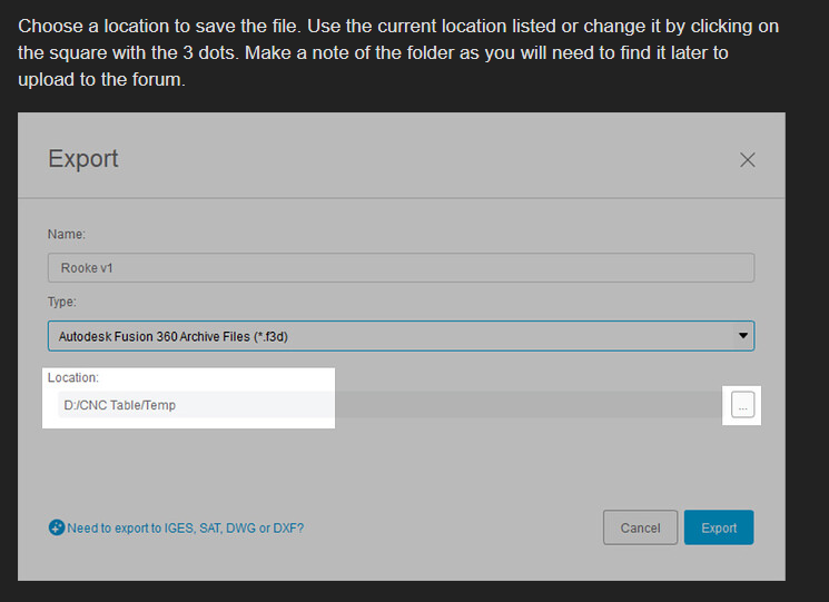
Thank you for replying! I will check when I get home. Can you explain how to save the F3D file to my desktop? I can only save it to the Admin file in the program. Can’t seem to export the file.
Its not a feature, its a method used in Fusion 360 to go through and find where the gap is. Basically, you draw a line across the geometry to identify where your gaps are. Look through this thread.
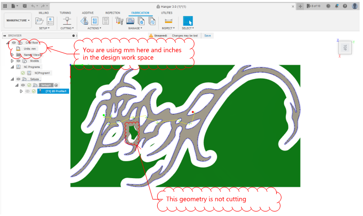
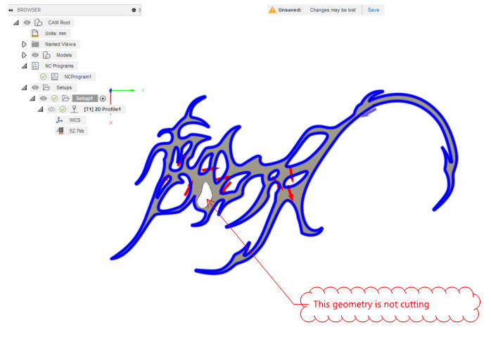
Did you select the body in the geometry tab when creating your tool paths. In your F3D it looks like you missed 1 piece of geometry. When I selected the body, it picked everything up no problem. I also noticed in the design workspace you are working in inches and in the manufacture workspace you have millimeters selected.
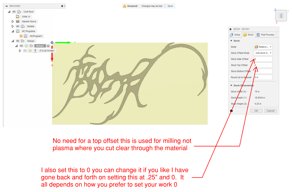
If you want inches in the manufacture workspace you have to choose it each time when you first enter the workspace. Click where it says units and you can select inches.
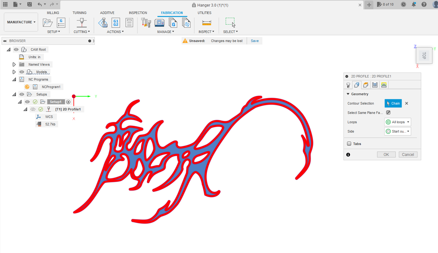
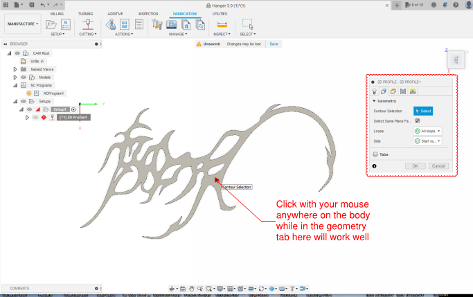
Below is what it looks like when you select the body instead of each individual loop. To do this you just click somewhere on the body while in the geometry tab and it will automatically select all the loops associated with that body. It also automatically assigns which side of the line to cut, and the direction based on the body.
I did select the body, I believe I had to select each inner shape, the whole design didn’t select when I chose the body. I’ll try it again when I get back to my machine/computer.
Thanks for catching the mm in the manufacture workspace. I will make sure that is changed to inches.
I must have missing that missing hole, I’ll make sure to select it. IS there a way to choose the whole body and each hole/loop will be chosen? Or do I have to choose each loop and body separately?
Would be grateful for suggestions on any other settings you recommend such as lead in, lead out, tolerance, etc. I have a crossfire pro. Hoping to get these files prepared and will be cutting some metal on Saturday.
Here is the file. You will need to edit the tool to match what you are using.
Looks like you extruded the piece to 1/4" if you are cutting this out of 1/4" you may want to use some feed optimization.
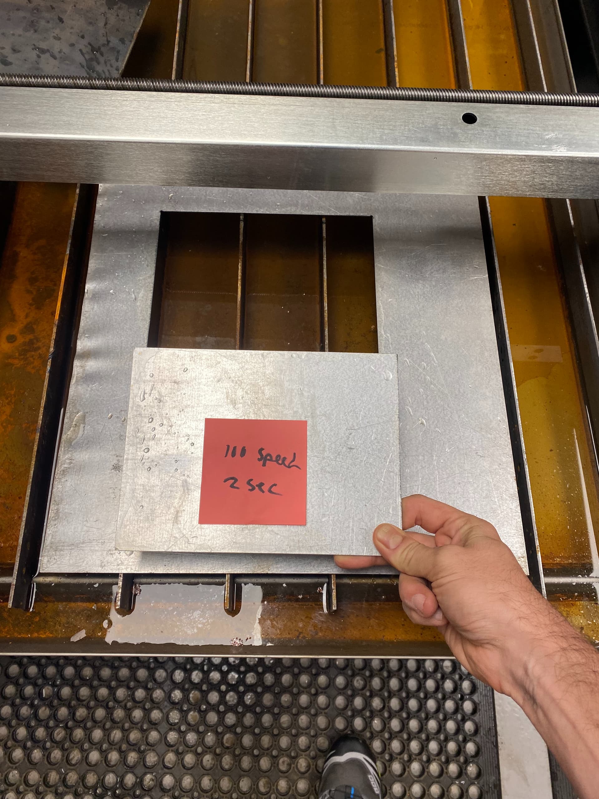
I would suggest doing some line tests to get your feeds and speeds. There are test coupons on fireshare.
Also, I would suggest cutting a 2 inch square with a 1 inch hole. Cut your test on the center of the line. The difference between your design dimensions and your actual dimensions will be your actual kerf width. Where this appears to be more artistic you probably don’t need your actual kerf width, but it is a good exercise.
thanks so much. What is typically a good feed rate? I have experimented with different feed rate and pierce delays with files from fileshare. Was planning on cutting this on something like 1/8". Probably something less that 1/4in.