This is still a work in progress but I did the same thing and have plenty of room with the enclosure on. I used a 1x2x1 aluminum channel and mounted it with magnets. This makes it easy to remove and clean. Your setup looks great.
Smiley
This is still a work in progress but I did the same thing and have plenty of room with the enclosure on. I used a 1x2x1 aluminum channel and mounted it with magnets. This makes it easy to remove and clean. Your setup looks great.
Smiley
That looks great!
I’m not the most knowledgeable about steppers or servos either. Maybe it’s a topic that deserves it’s own thread.
Amazing build mods… thank you for posting… many I plan to implement… might I ask a question? why are the drag chains so wide? they open up so you really need only slightly more room than the wires they transport…
Also I to am interested in more Z clearance… I was thinking of precision ground “blocks” acting as spacers like 123 blocks… please keep in mind I am not nearly as far along as you are… that is why I ask. thanks…
The inside dimensions for mine are 40mm x 15mm or 1.57" x 0.59".
The y-rail cable carrier will need to carry every cable for the X & Z axis.
So for my setup, the cable carrier will be filled. If need be, I can get a smaller flood coolant hose.
The cable for the tool setter will be wire tied under the cable carrier rail as it needs to exit a the front of the left Y-rail.
I let the epoxy sit for a week, but is was set within about 24 hours.
Today was a busy day and I was able to:
Here are some pictures of the 3/16" Y to X spacers. I will likely remake the left one to move the cable carrier attachment further away from the limit switches. I had to do a little trimming to get to the hard limit and clear the switch.
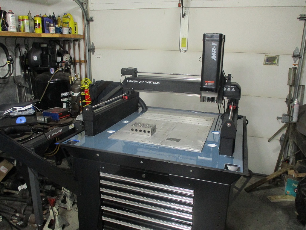
Here are some overall pics showing the current state of assembly.
Setting the limit switches was a pain… I tried setting them by clicks, then used the 2 multimeter method, but still really wanted to “know with dimensions” how precise they were set to each other. What I ended up doing was starting with the Y-1 (Left) and setting it about 0.060 from the hard limit. I jogged the machine (.001" jog speed) away from the limit then ran it back until it stopped in error due to limit being tripped. With it stopped, cleared the limit error, zeroed (0.000") the Y axis, backed away enough to reset, then jogged back into the limit. Did this about 5 times and It would stop between -.001 and -.003". Then disconnected the Y-1 limit switch and installed a jumper in the harness so the limit error could be cleared.
Then I adjusted the Y-2 limit switch and did the same back up and jog into the limit. I made several small adjustments to the Y-2 limit until it would trip and stop the machine in the same -0.001" to -0.003" range. Now I am confident they are set as close to each other as possible.
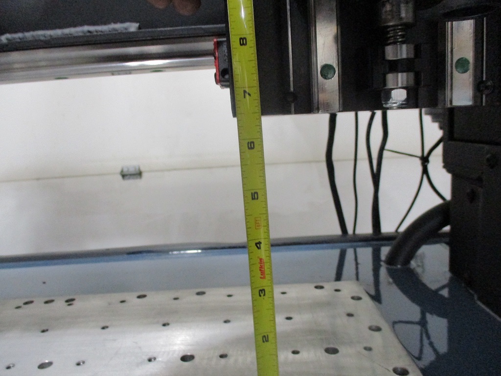
The MR-1 spec is 5.5" clearance to the X-rail. This is measured on my additional baseplate that was .750" thick and stands proud of the Langmuir plates about 0.060". Once everything is surfaced it will be a little more than 6.5".
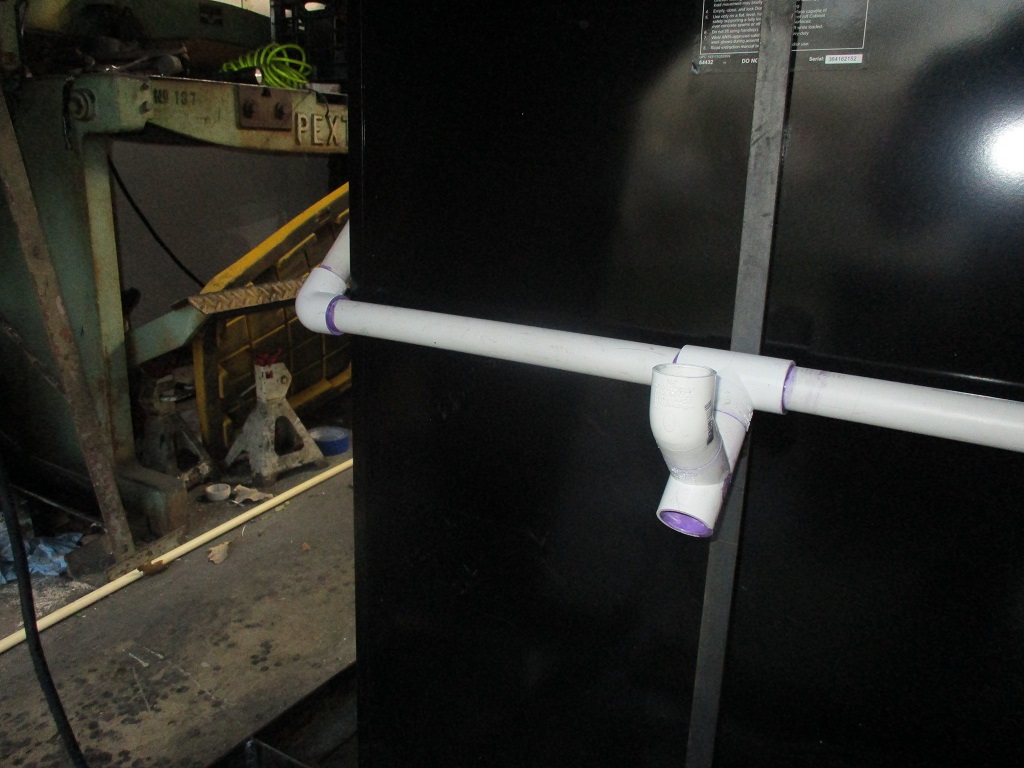
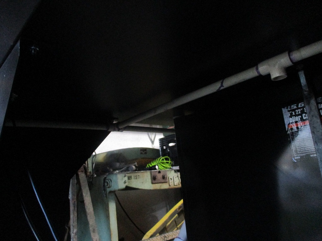
Hoping to have some time in the evenings this week to get the PVC flood coolant drains done, then fine tune the placement of the control panel, the E-stop and the control panel power and spindle power switches so they are more accessible and possibly work on the cable control rails for the X/Z wires.
It is awesome to have the machine under power and able to move!
I am curious how you arrived at the size of your additional base plates and how much functional gain you expect to get out of it.
By the way, nice job of it. Looks great.
Thanks,
sbdon
Since you only get to install the baseplate 1 time, I figured it should be as large as possible to allow clamps to be outside of the milling surface as well as have mounting space for a 4th axis - even if it is manual.
X travel is 23.0" and Y is 21.8" with the stock baseplate being 20" x 20.5".
Several guys had already installed a 3rd baseplate by the time my machine was delivered, so there really wasn’t any concern about surfacing it. I tried to order a 3rd baseplate from Langmuir, but was told they were focusing on shipping machines and would not sell me one.
Faced with making my own, I took a harder look at the width knowing the limiting factor is what can be surfaced. Other people had used the 2" fly cutter to surface their baseplates, so taking it 1 step further… 23" travel + 2" fly cutter = 25" surface area.
I also wanted to keep 2x2 bolt spacing as close as possible from plate to plate across the entire work surface, so that put some constraints on adding the width in 2" increments. 2" (22) would work, 4" (24) would work, but 6" (26) would require an even larger fly cutter and might have issues So I settled on 24" wide.
With the 10" rear plate the overall baseplate is 24x30.
That’s great. Thanks,
I don’t want to sound greedy but is there a STEP file for the factory base plate. They won’t sell me one either.
sbdon
Sounds like if a person had several made up they would sell LM said no to my request also…
I have a dxf but not a step. I made my plate on my manual mill, so I did the drawing in 2D with nanoCAD 5. I haven’t drawn anything in Fusion 360 yet… that will be something else to learn when the time comes.
Would you post the dxf file? A whole lot better than nothing. It would be appreciated.
R,
Don
I have a couple of brand new factory base plates to sell. I’m not using the factory ones in my build, so I have two extra.
Only one base plate available now, one is sold.
Located in western WA. Feel free to Pm me.
Both base plates are sold.
what are you going with Amos?
I got a good deal on a pair of cast iron tooling plates. Looks like they are somewhat more expensive now.
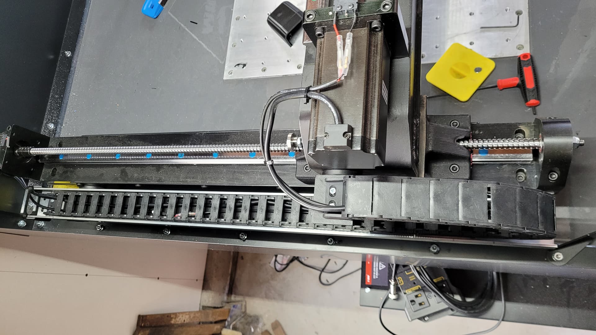
Finished with the fabrication of the cable control rails. I did end up extending the Z limit switch cable about 4’, but once that was done, everything else fits like it should. There is ample cable length to tuck the controller box up under the left hand side. All the cables are currently in place, but I left most of the covers off for fine tuning lengths at each motor/switch/device.
Here you can see the probe and flood coolant hose. Both are longer than they need to be:
Here is the backside of the spindle:
Here is the backside of the X-rail:
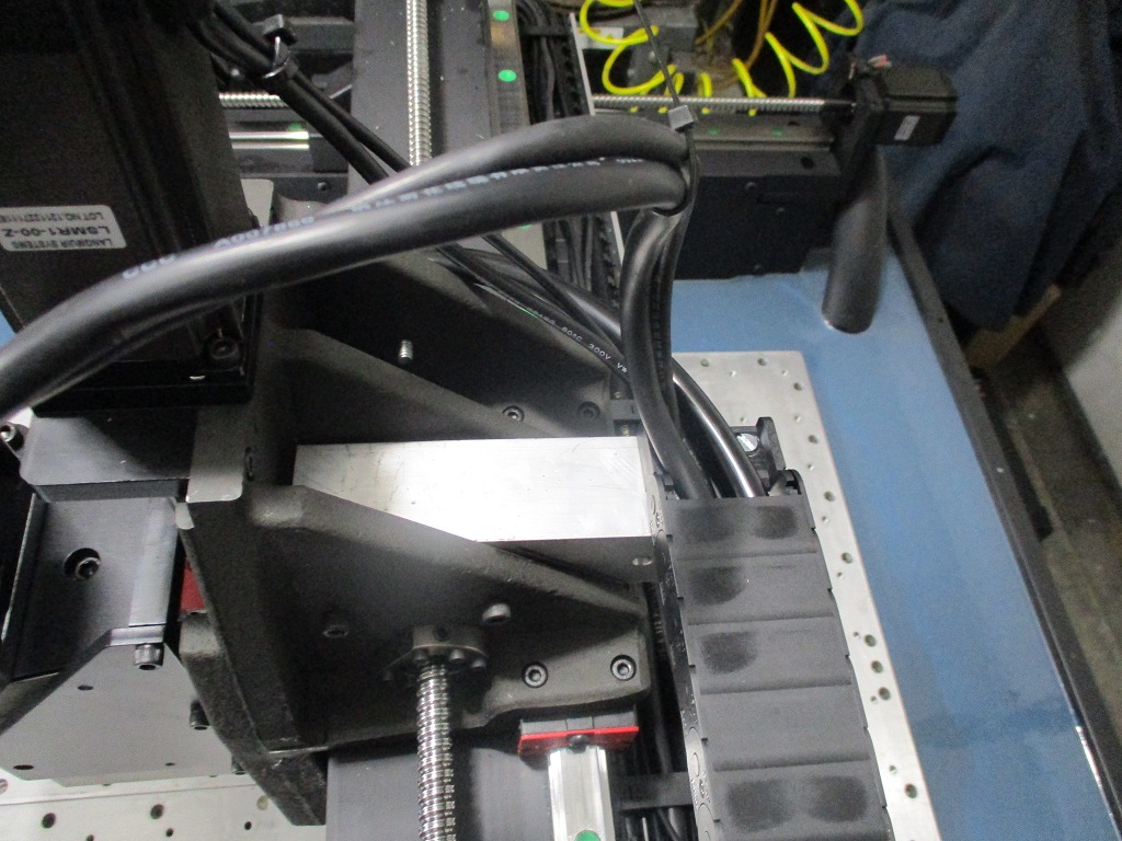
Here is the X to Y cable transition on the remade 3/16" plate:
Here is the Y1 to conduit transition:
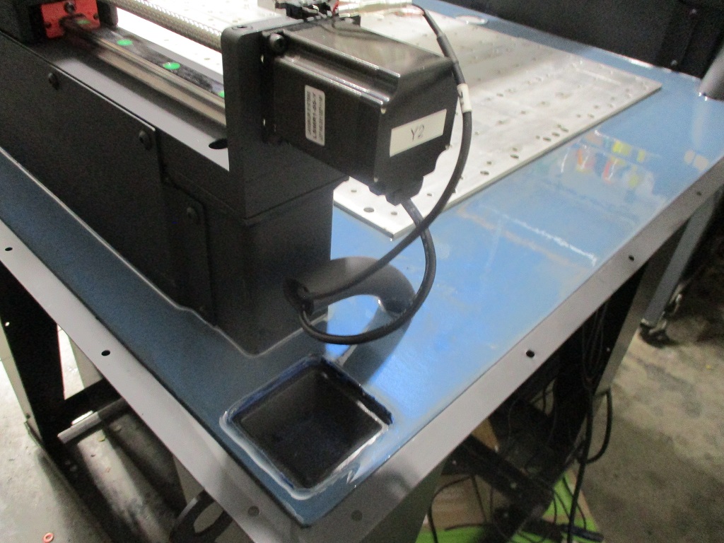
The Y2 to conduit transition:
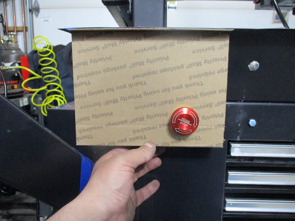
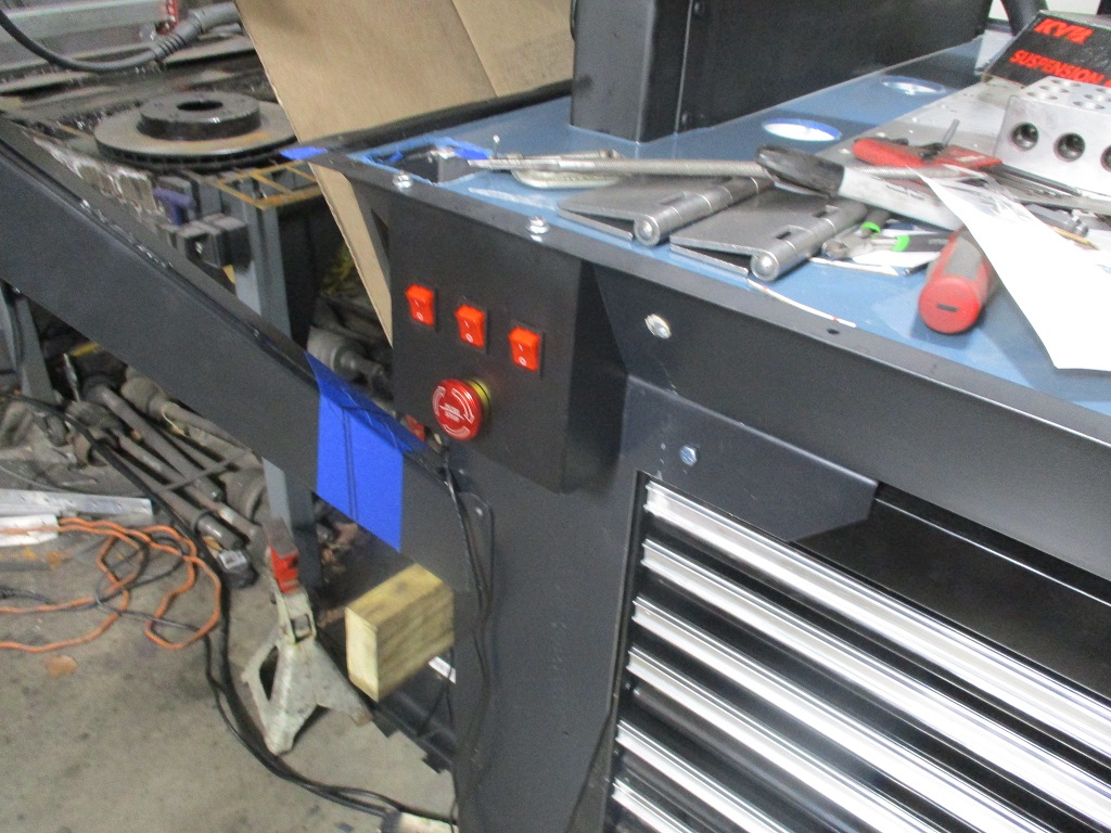
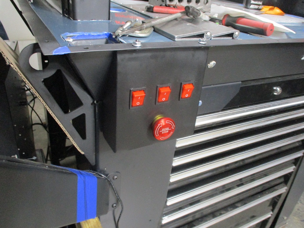
Here I am getting started with the relocate the E-stop, 120v switch and 240V switch to the front of the machine:
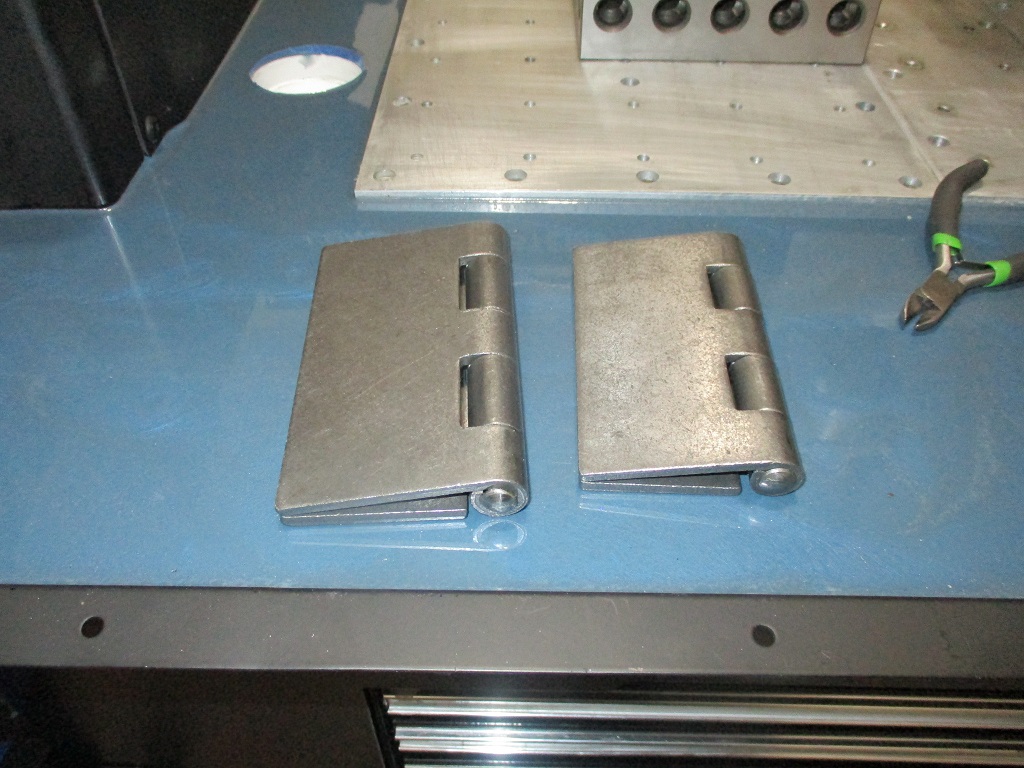
Here are the hinges for the computer stand. One to swing the arm out of the way, one to drop the laptop tray vertical.
The fabrication of the auxiliary control box is done. It has the e-stop and switches for the 240V spindle, 120V control power, and 120V for the lights. The wires will pass through the leg into flexible conduit back to the control box.
i like that, i moved my estop up but moving those two buttons would also be super helpful.