My MR-1 arrived a couple weeks ago. Since then I have read every thread on the MR-1 forum, reviewed all the installation documents and started the assembly and modification process.
There have been a lot of great modifications to the assembly process posted, which I am thankful people have shared. I am adopting some of them as well as creating some newer ones as well… I just can’t leave well enough alone…
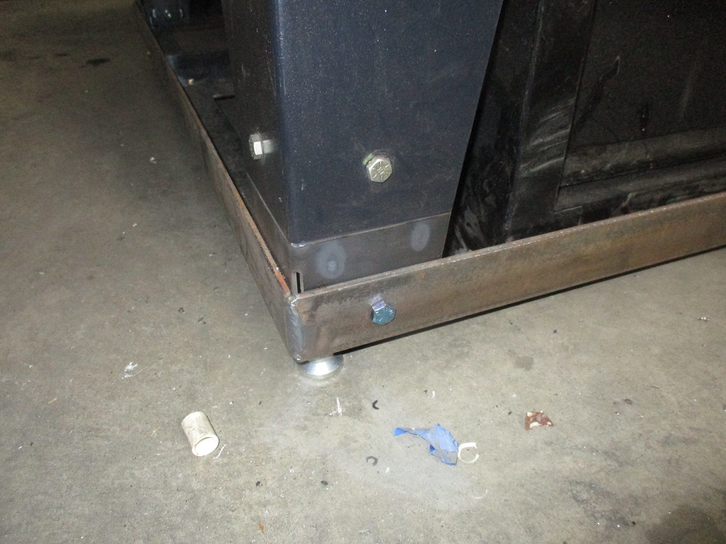
First modification is an easy one. Long bolts for attaching the legs. Using these will directly anchor the legs to the concrete base and result in overall more solid platform.
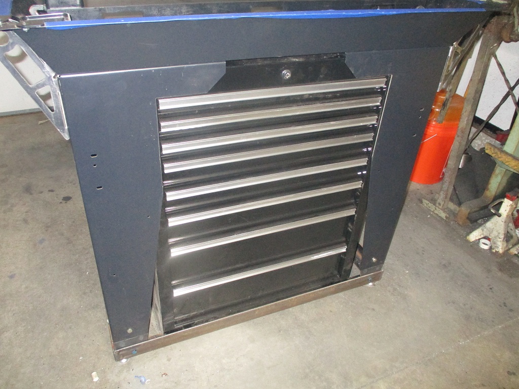
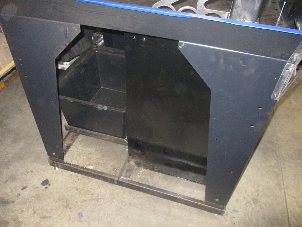
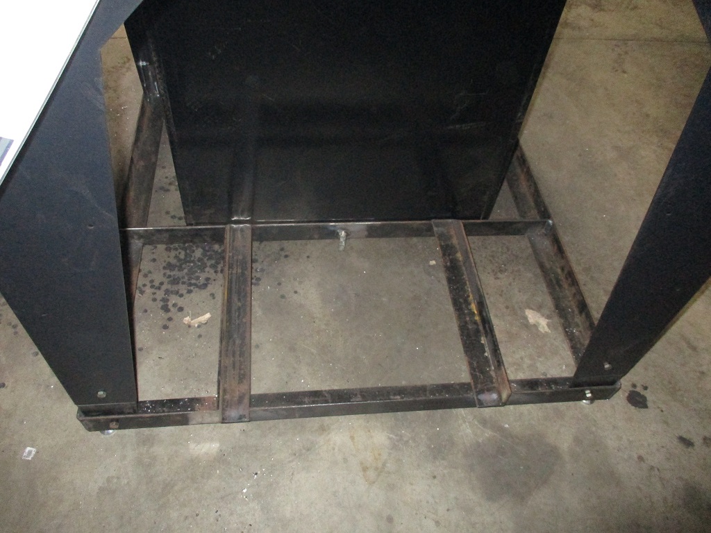
A 2x2x3/16" angle base was also made so all the legs bolt to it. It locates the tool box and the flood coolant tub, and used the MR-1 leveling feet. Also added a jack bolt for the back of the tool box to help support its weight.
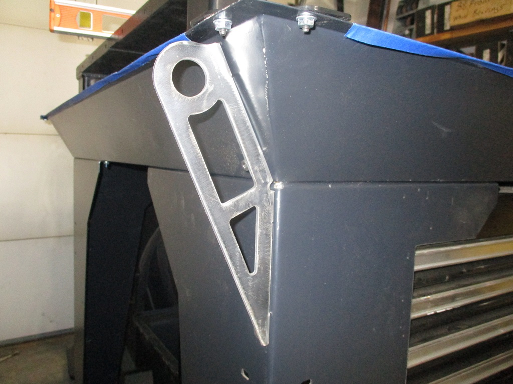
While I should be able to use some pipe under the frame to help roll the MR-1 into its final place, I went ahead and made some lift brackets for the 4 corners:
I have also started the process of raising the Y rails by 3/4". Jack bolts on all 4 corners push down on the leg brackets will hold and level them. Additional brackets bolt to the front verticals and bolt to the leg brackets to lock the front edge in place. Additional gussets were cut and welded to the vertical uprights for addition support as well as creating an X on the base of the verticals to help engage the concrete.
Next I am going to work on the side plates for the y rails. Not sure if they will work with the y-rails being raised 3/4" and might need to be modified as I want to fill the cavity between the plates with concrete as part of the pour, so they will need a little work. I might also have to remake them if they
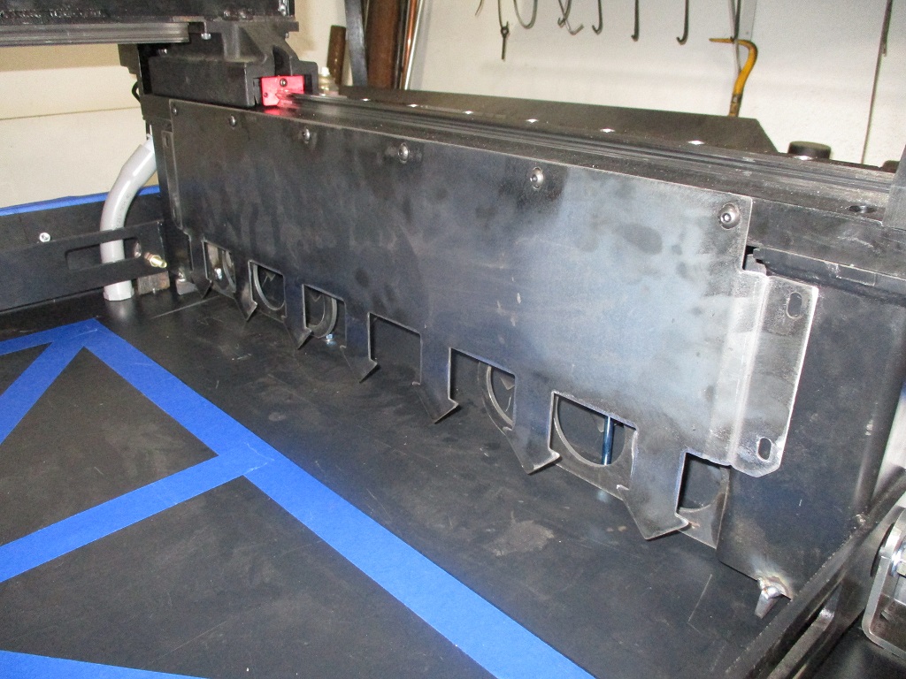
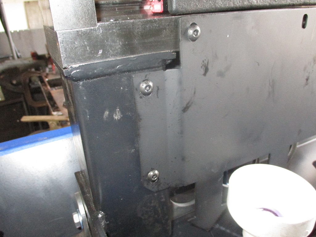
The y-rail side plates are now too short to seal at the bottom, so a new one was made that was 3/4" taller. It is also wider so the sides can be offset and bolt to the verticals of the Y rails. Bolting these side rails to the verticals is key to sealing the space under the y-rails as well as holding the verticals in position during the pour with the top of the Y-rails removed.
I didn’t have any 14ga, so cut one from 16ga just to check the fitment and have an order in for the 14ga.
I am planing to raise the X-rail anout 2" overall with 3/4" coming from the Y-rails.
Primarily this is to fit larger parts on the work table, allow ample room for a 4th axis, and to keep the vice and pallets from taking up valuable space in the maching window.
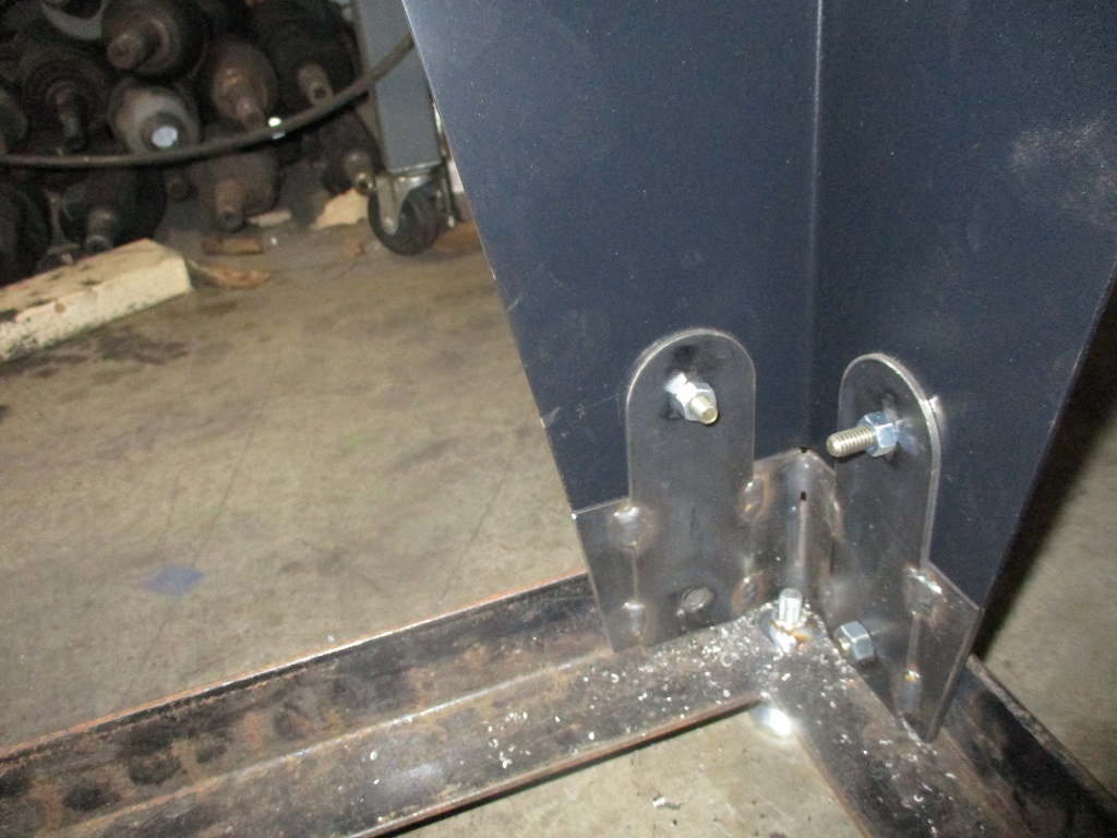
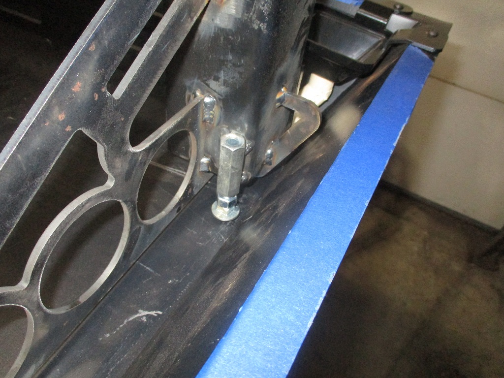
My machinist level came in so, I spent some time releveling the pan, then the Y-rails, and then added some brackets to hold the rails after I squared them up (picture of bracket a little later). I still need to double check co-planarity with the Langmuir tool, but suspect it will be close.
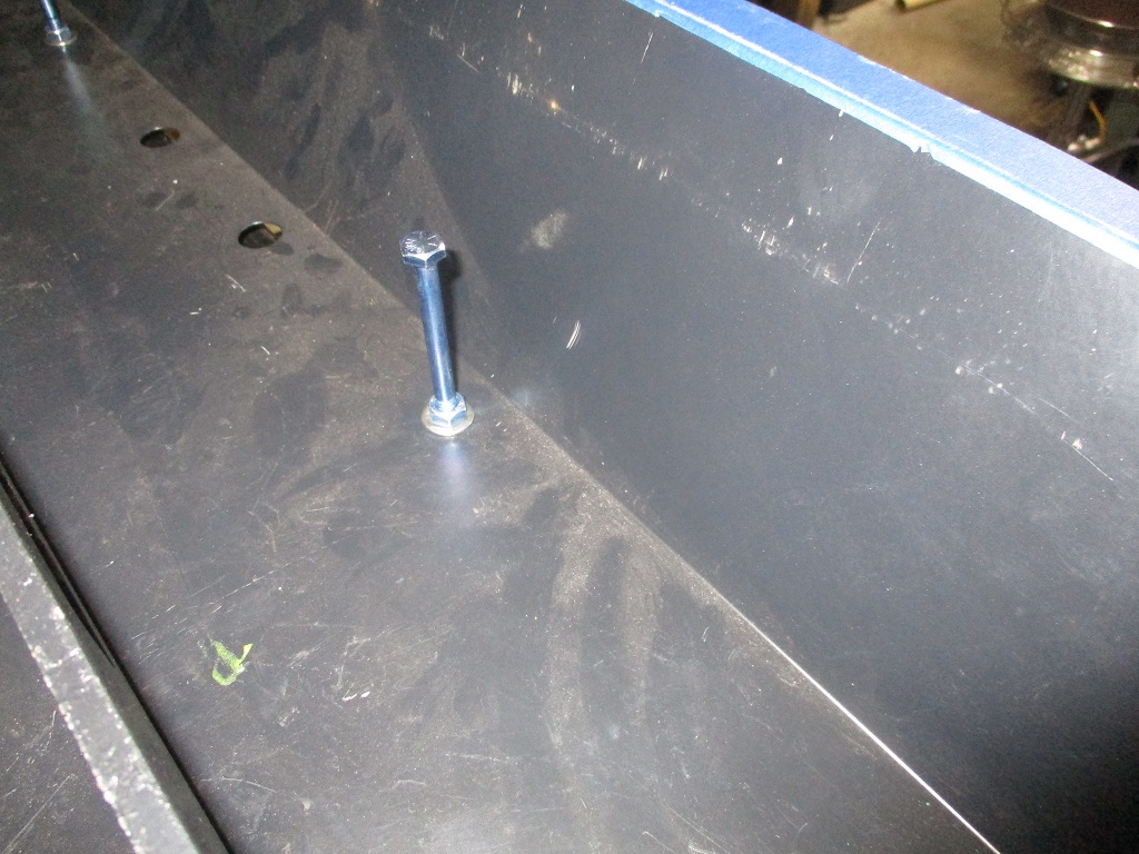
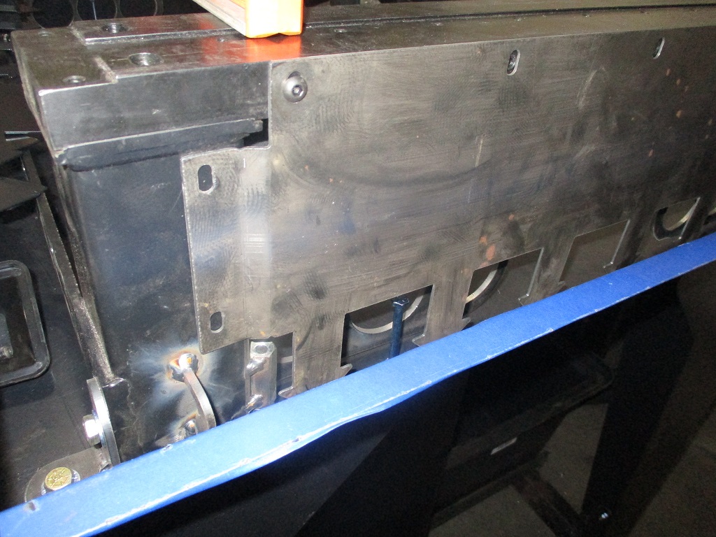
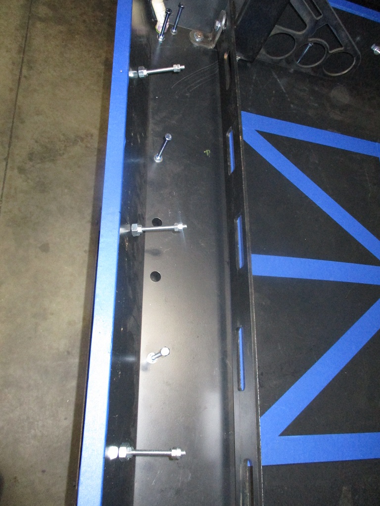
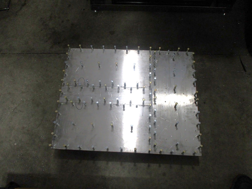
Added 3 more studs on each of the sides of the pan to help lock the pan to the concrete slab. Just some 3.5" long carriage bolts:
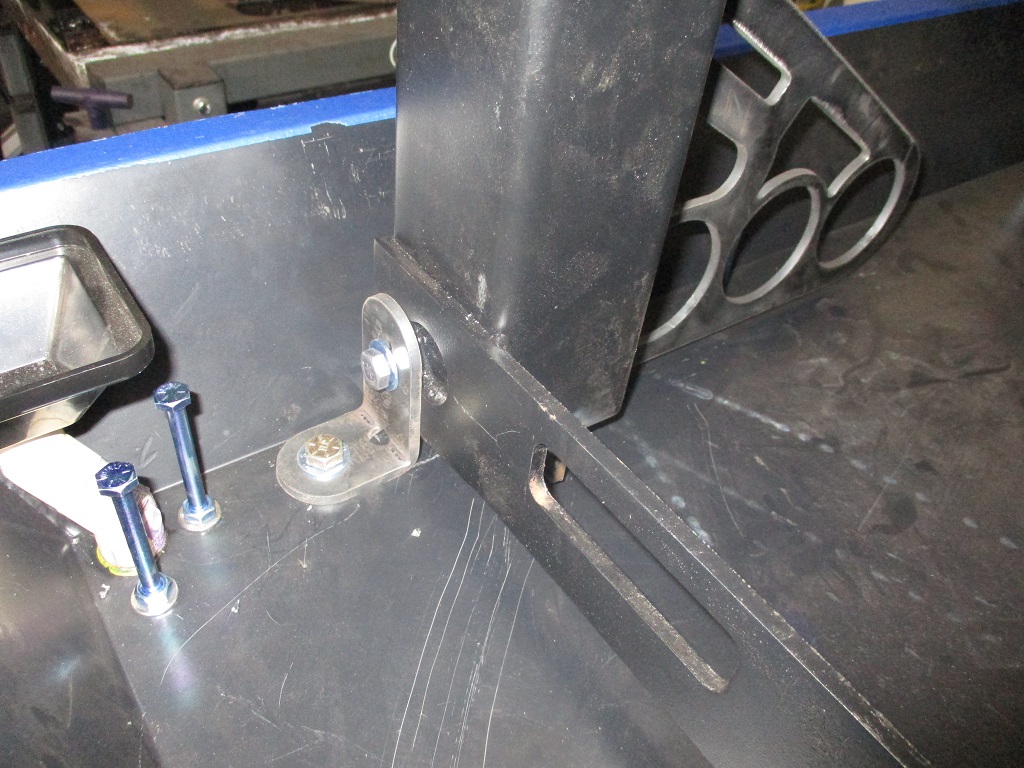
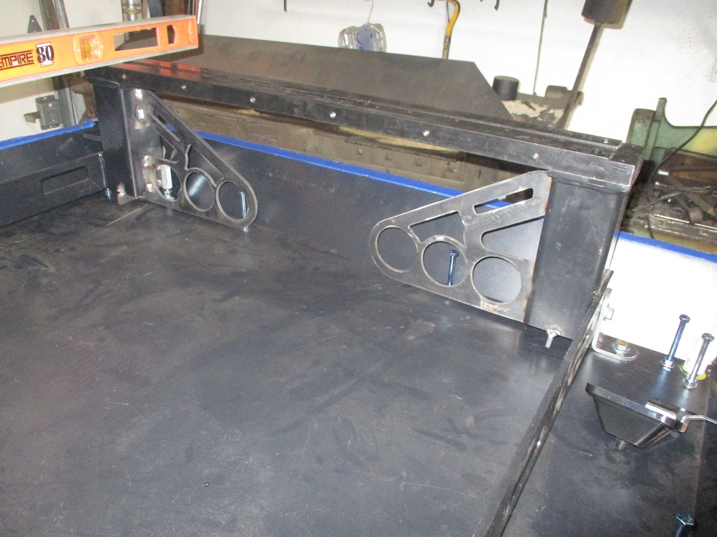
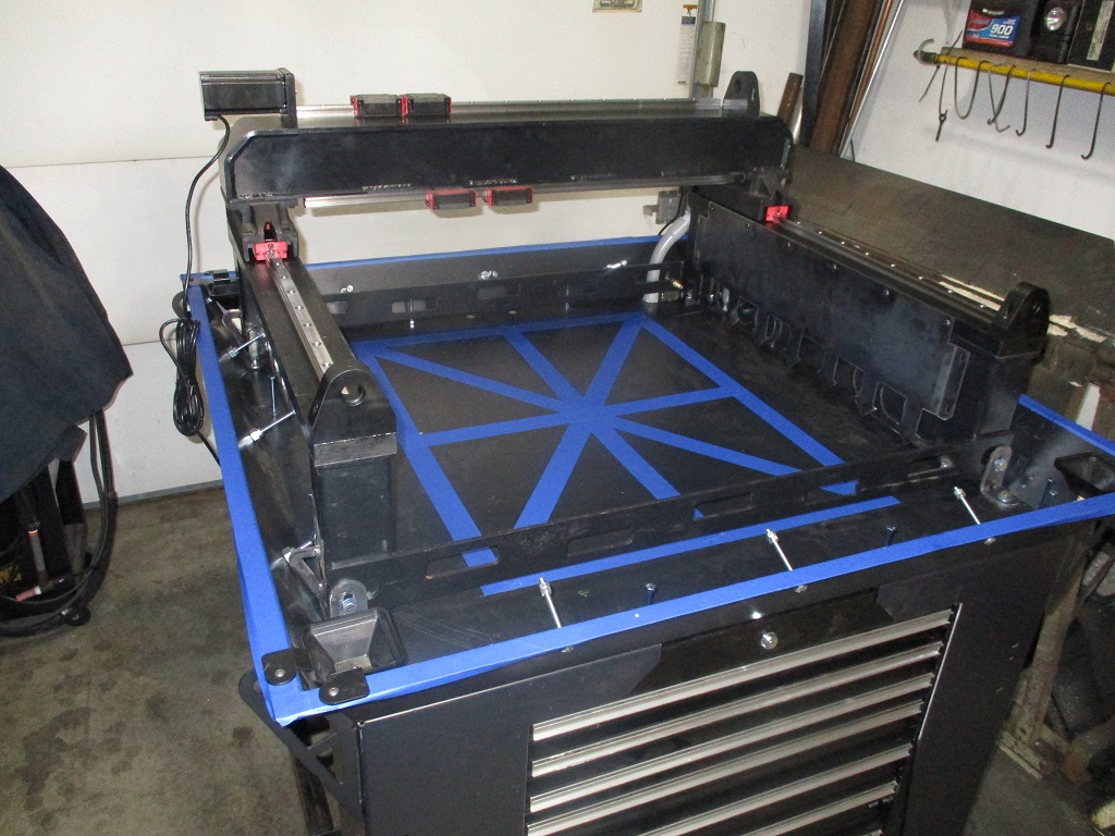
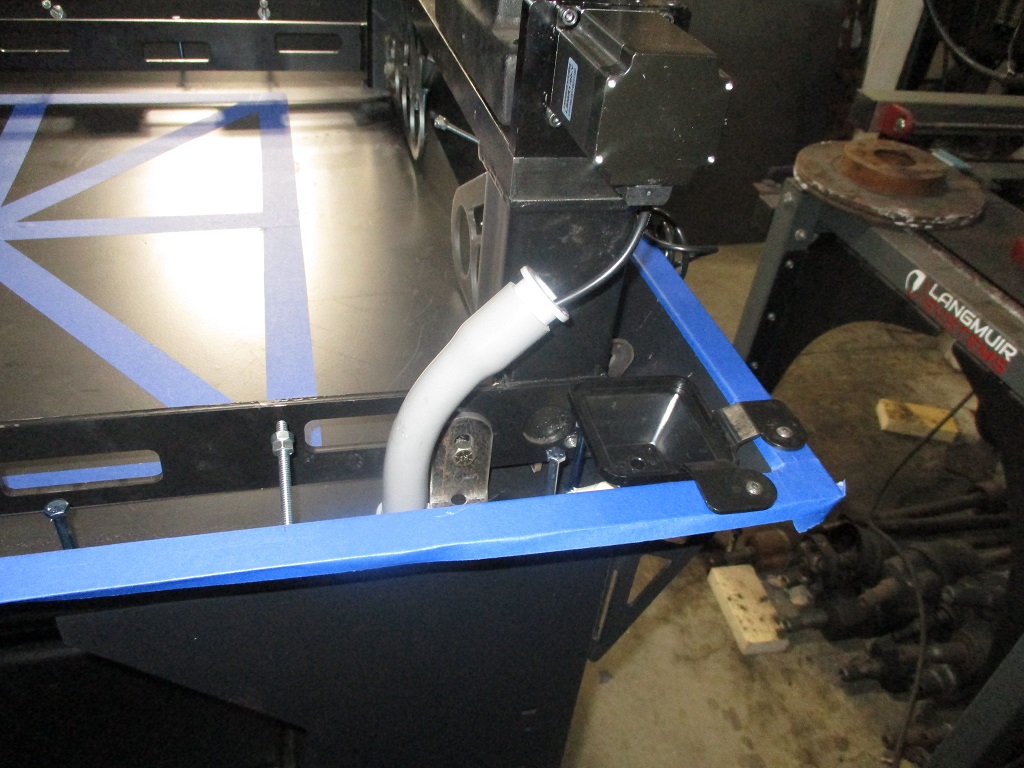
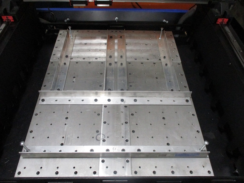
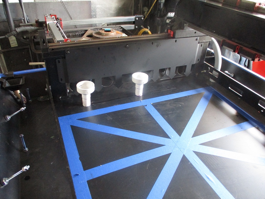
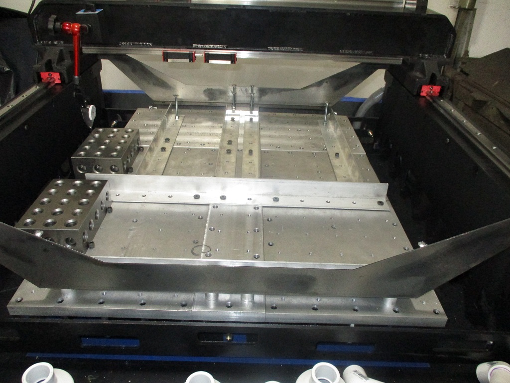
Then I started mocking up the Y and X rails primarily to start thinking about how I am going to run the cables. I was able to move the X-rail up and back the length of travel of the y-rail with my pinky finger. The blue tape in the center is my planned oversized 24x30 base plate.
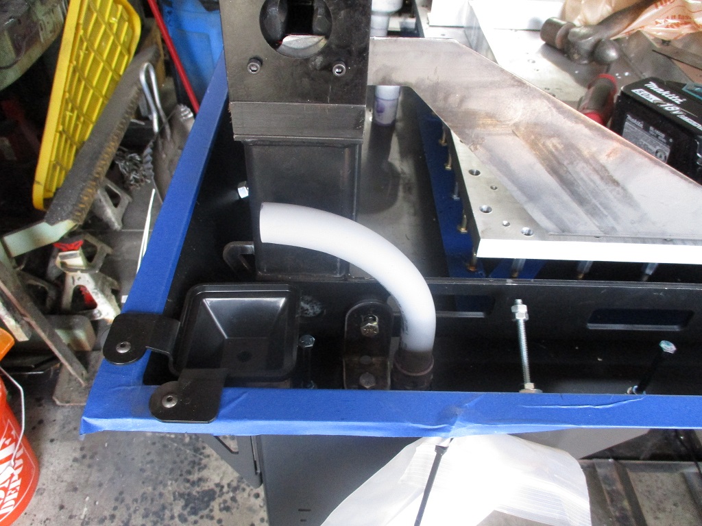
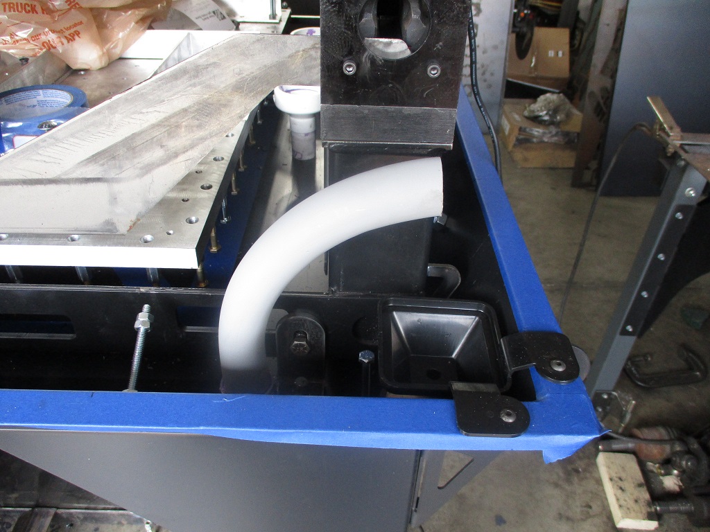
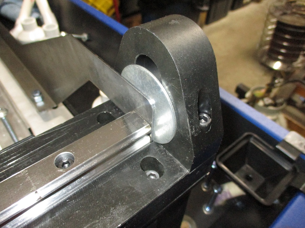
For the Y-motors, al cables will be routed through some PVC conduit under the motors and through the concrete base. I need up upsize at least the left side to 1" from 3/4" so that I can run the X rail cables through it as well. In this picture you can also see the bracket that holds the rear of the Y-rails (one per side).
I am going to try to work on this some more after work this week. I want to paint the Y-rail side plates, finish the PVC conduits for the motors and add some side drains between the base plate and the Y-rails. Then I can move on to drilling/tapping the additional plates to enlarge the baseplate.
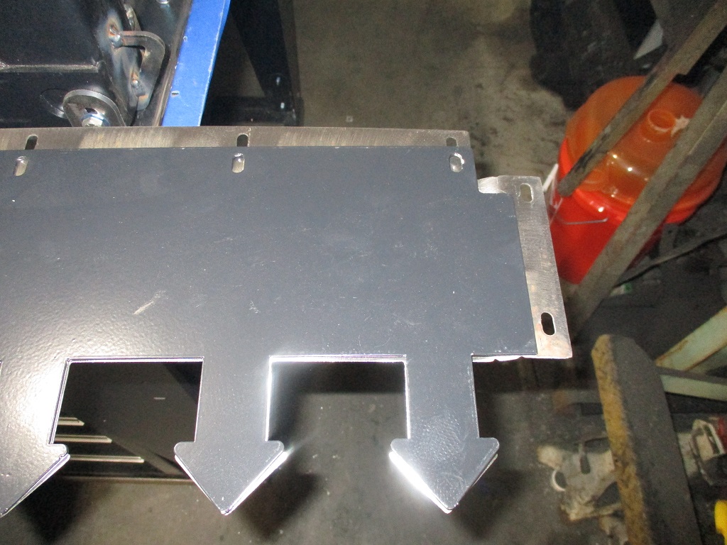
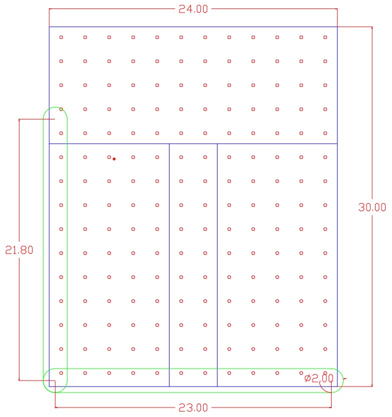
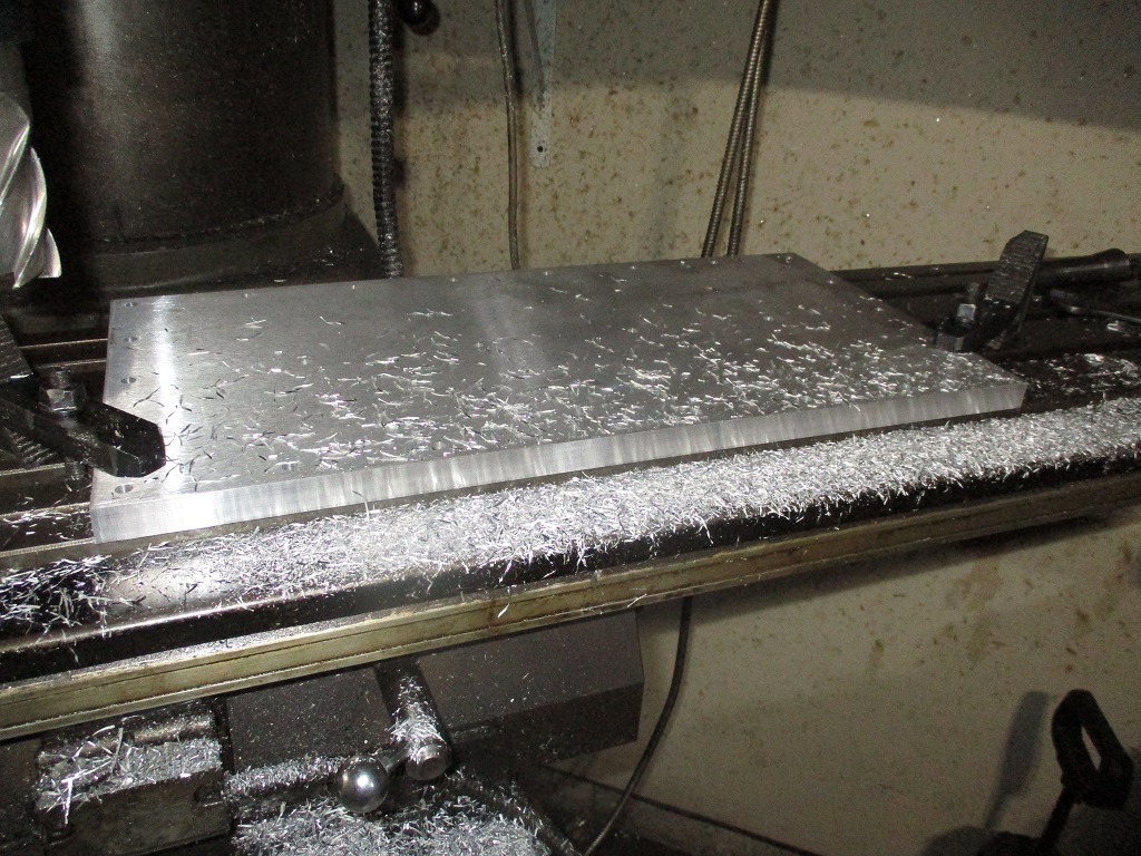
I burned a vacation day today to get started on the oversized base plate. First thing I noticed was the rough cut perimeter of the base plates was not square with the 2x2 hole pattern, so I put them both on the mill to square all the sides to the 2x2 pattern.
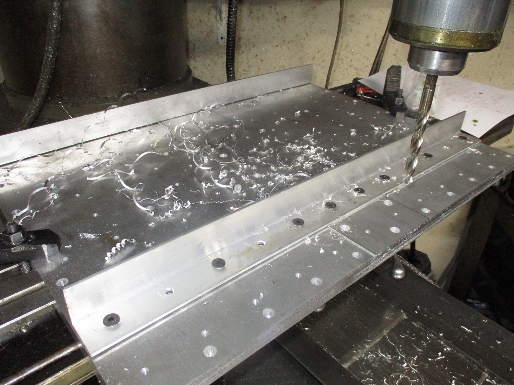
Once they were square, I mocked up the 4" spacer piece and checked the hole centers… and needed to take about 0.095" off in total between the two inside surfaces to keep a constant 2x2 pattern across all the plates. Once that was done, everything was bolted/clamped and started drilling out the pattern on the 4" center plate. Once I had some locating holes for the 4" center plate and bolted it into place, I trued up both ends.
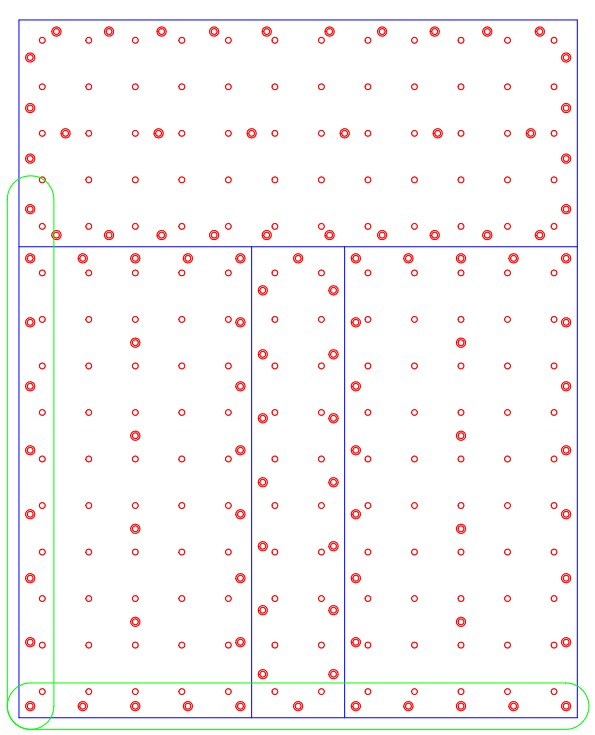
I did change up the anchor pattern on the 4" and 10" plates in my drawing. Originally the anchor pattern was mirrored from the current plates, but then I thought the anchors would be too close and might get hung up on the concrete rocks. So I offset them to increase the spacing between anchors.
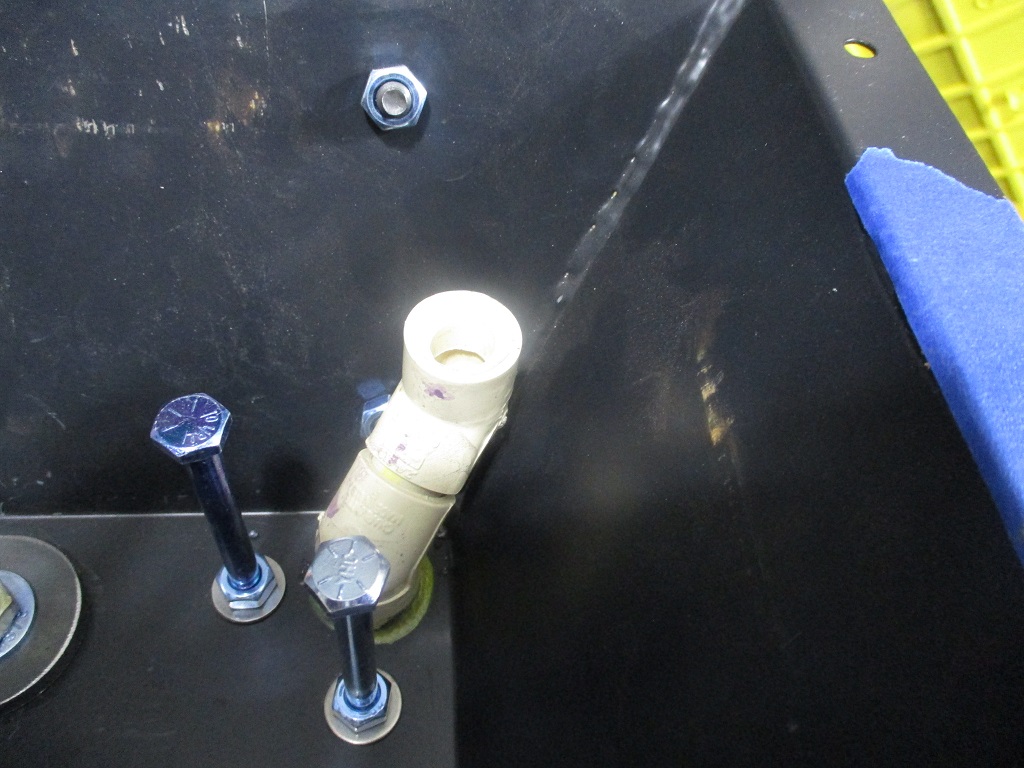
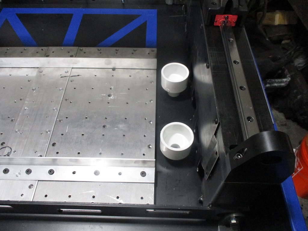
Here is what I am thinking about for drains between the base plate and the Y-rails. 2X3/4 PVC reducer. I will need to chuck it up in the lathe to shorten it so a coupler will fit snug with the tray.
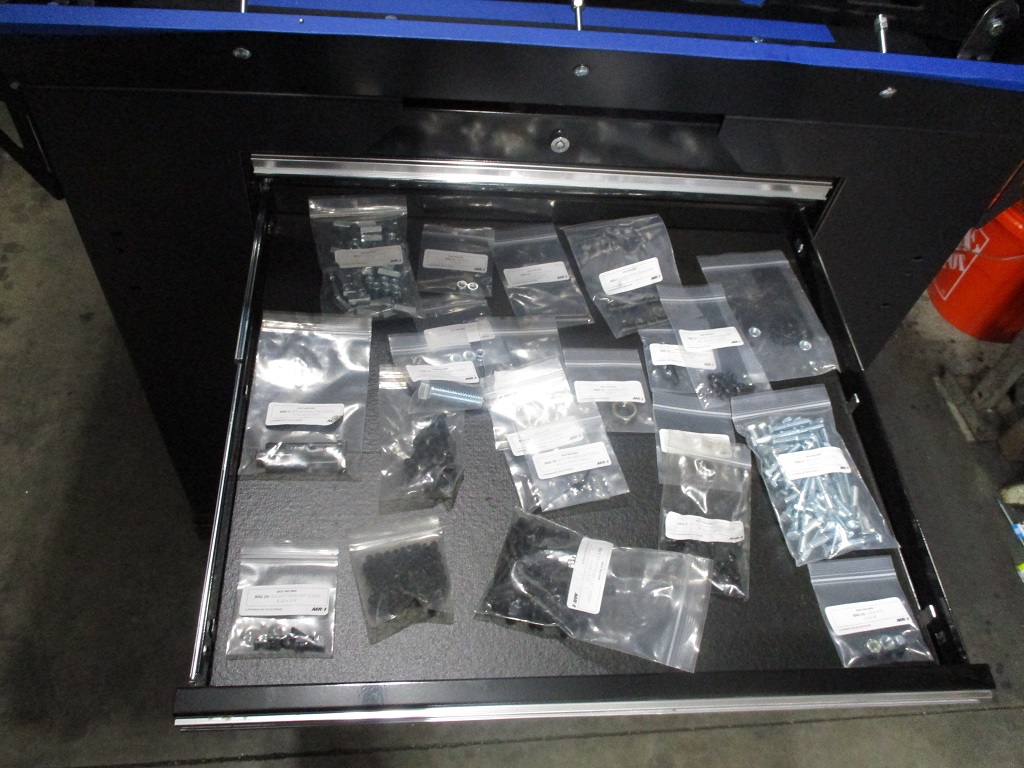
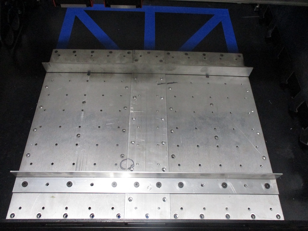
Took most of the weekend to finish milling, drilling and tapping the new baseplates, making the aluminum angles, and installing all the anchor bolts and hardware… glad that part is done!
While I still have the Y linear rails in place, I want to use a couple of 2x4x6 blocks to make the 2x2 pattern parallel with the Y-rail on the left in the picture. Then I will make a couple of locating brackets from the base plate to the y-rail verticals front and back that can be used when setting the plate in place and locating it parallel with the left Y-rail.
I suppose you have made the added width exactly to where the X gantry can reach for surfacing? I went a different direction with anchor points in the concrete itself in the X direction but extended the plate in the Y, but like your solution too.
Here is something to watch out for … I had a bit of a challenge with the symmetry of the X axis, when I rotated it 180 degrees to surface the back side of my extended plate it surfaced fine, but when I rotated it back to do the front of the plate the resulting two surfaces (front and rear) were very slightly off co-planar. The result is a tiny tapered ridge (less than a thou though) between the two surfaces that showed that the X axis was not perfectly symmetrical in the Z plane. If the machine is with a standard sized plate it will not show up since its all done with the X axis not rotated.
I ran an indicator and I do not think it will be an issue, it’s very minor and the vice bases even things out. The correction would be to shim the X axis to exactly match the 1st cut surface using an indicator so the 2nd cut surface will be exactly planar.
Correct, I enlarged the width of the plate beyond what could be surfaced with the 1/2" endmill, but still able to surface it with the 2" fly cutter.
I am in no rush getting the mill up and running, so I am happy to take my time and do everything I can to maximized its capabilities. I was planning to take my time on tramming the head to get is a close to perfect on the front section, then do the same on the rear. If it doesn’t work out, I will make the rear just a few thousandths lower so I can shim whatever is attached to the rear plate.
With the center plate in front being about 0.055" thicker/taller, that gives me quite a bit of material to play with the setup and alignment before I ever cut the OEM base plates.
For the center drains I would potentially look for some aquairum bulkhead fittings and reverse them so the slip fit is angled downwards.
Then you can detach the pipes if need be with very minimal stick out.
That or have a coupler on the inside of the tray so it is locked in by the surrounding concrete acting as the slip fit joint to pull out anything that hangs below the surface of the tray.
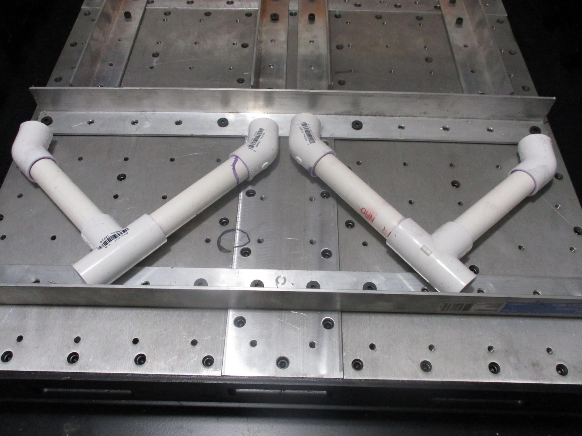
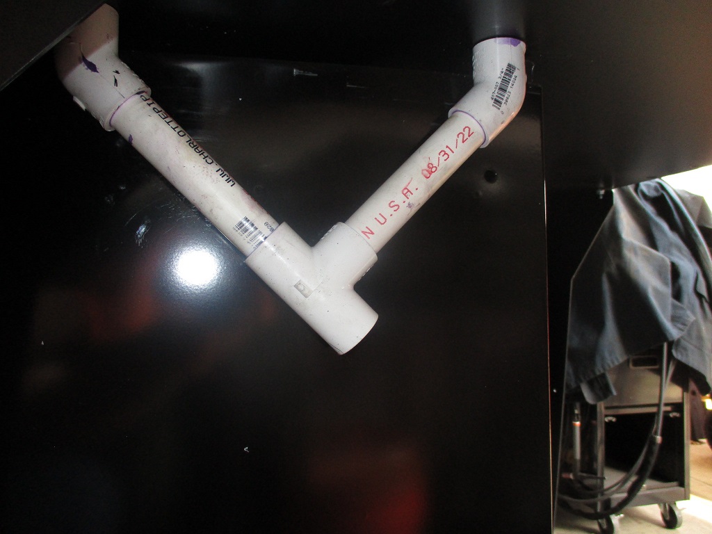
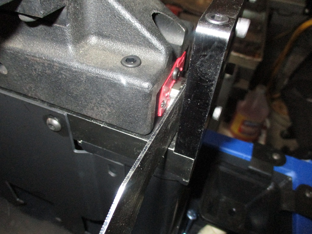
Finished up the cable PVC tubes. Kept the 3/4" on the right, but switched to a 90 and a 1" 90 on the left. The 1" is large enough to feed 3 motor cables through.
Also figured out how to properly locate the baseplate in the concrete and keeping the 2x2 pattern true to the left Y-rail. Used the supplied Langmuir baseplate brackets, with a 3/4" spacer to account for the raised rails. Then pulled the Langmuir brackets to the right so they are tight to the right side of the left rail. Then installed some bolts, 2x4x6 blocks, and ran a dial indicator down the length. Loosened the bolts holding the Langmuir brackets to the baseplate and squared it up.
While planning for this, I noticed there was room for the Langmuir brackets to fit between the linear rails and the end plates. I used washers to close the gap and doing the placed the front of the plate right at 8 9/16". I did have to offset the rear spacer about 7/8" to make the Langmuir brackets fit the rear gap.
Now it is time to take the top plates of the y-rails back off , reinstall them and make sure everything stays true and will go back together. It need to be able to do this to allow the area between the Y-rail side plates to be filled close to the top with concrete.
I think you are going to get small amounts of coolant dripping down your cable chase. Generally, the end of the cable chase is pointed down with enough vertical distance to keep drips from being able to wick up on the inside of the tube.