Tight work just love your setup
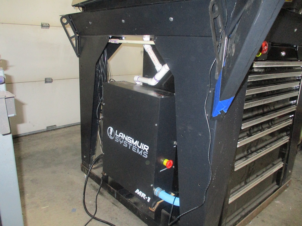
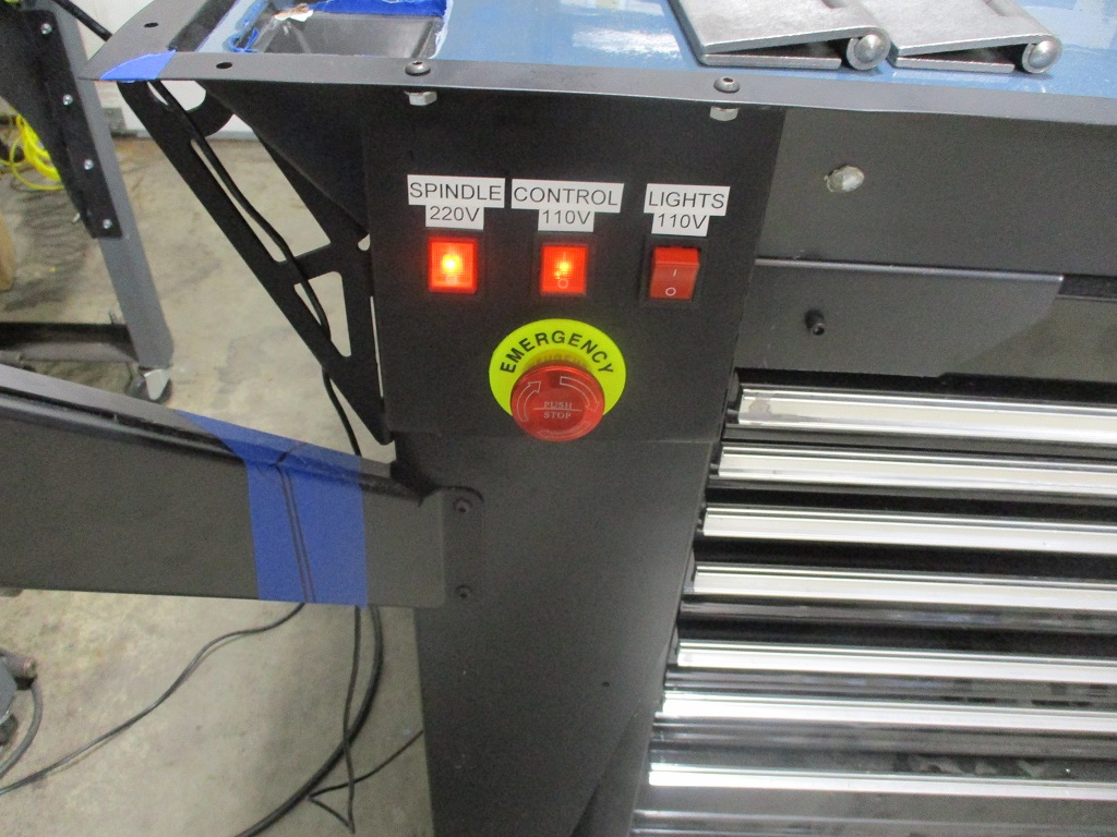
Finished up the relocated wiring. Made a base for the control panel from 1 1/2 x 1 1/2 x 3/16 angle and lined the inside with 1 x 1 x 1/4 wood corner molding for electrical isolation. Had to do a minor rework to the left drain pipe so the control panel could be recessed further.
Tested everything and it works like it should. Even had time to do the spindle run in program.
3 Likes
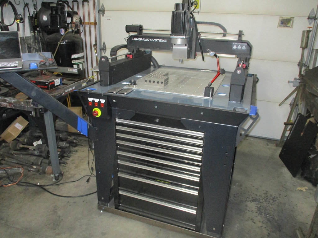
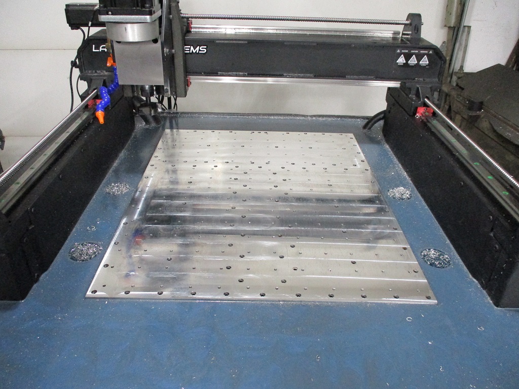
Made some chips fly today!
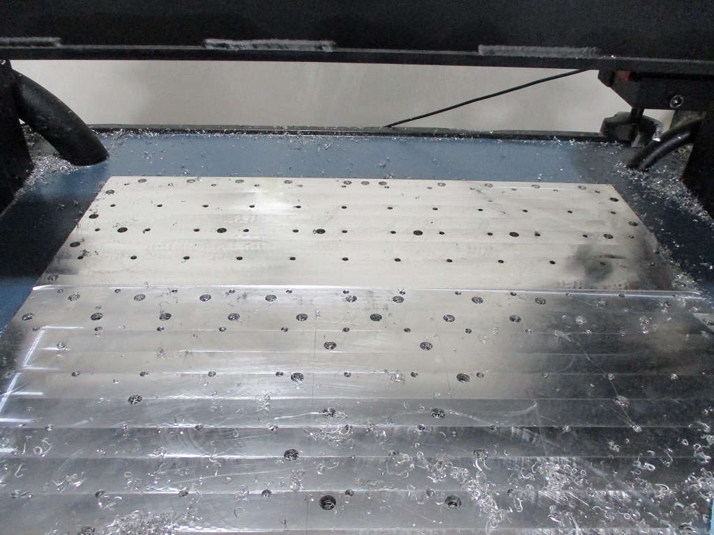
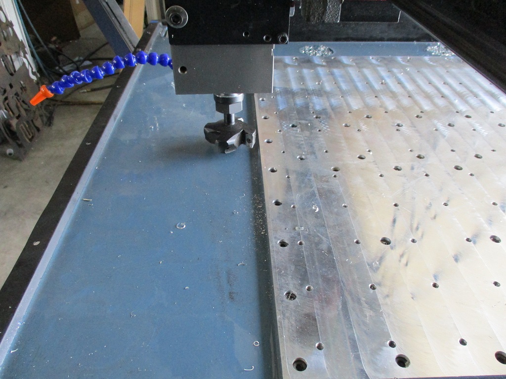
Started the first couple of passes on the thicker portions of the base plate. I use my 2.5" flycutter with the Langmuir bit holder and insert, set the rpm to 1500, feed to 15 IPM and used a 1" step over, and in manual mode.
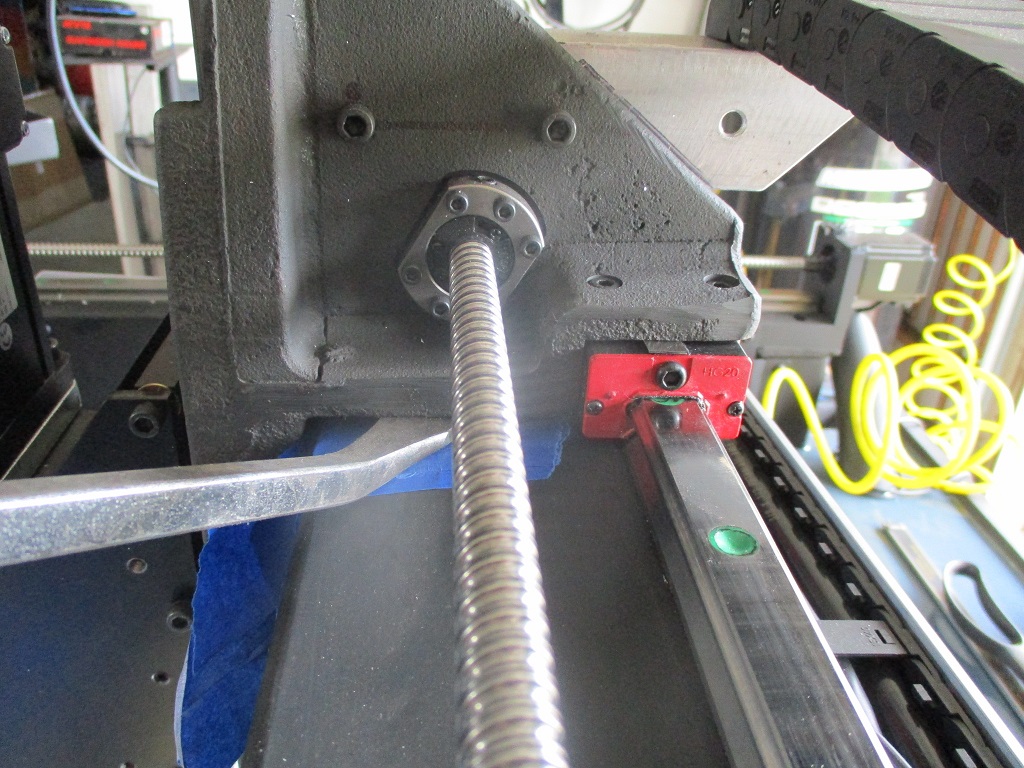
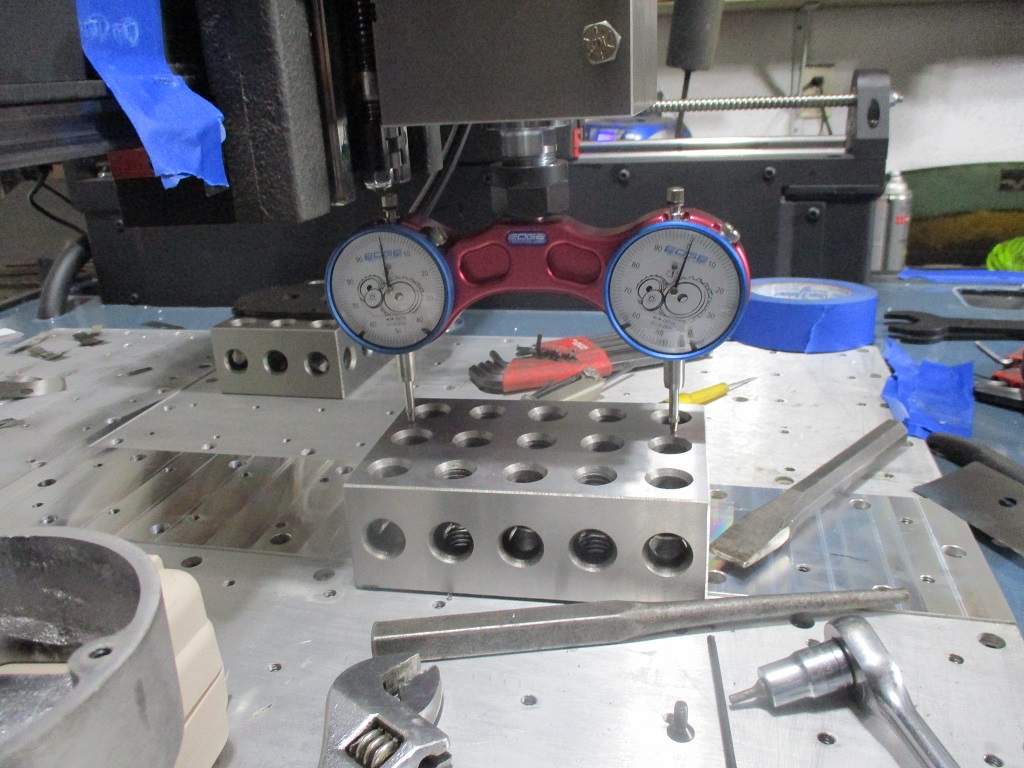
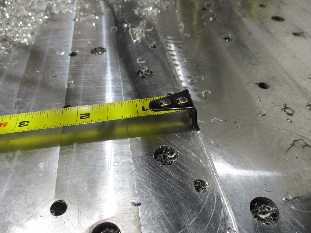
From there I stood one of my 2x4x6 blocks on end and ran the indicator down the side. This showed the Z out to the point I needed to add some shims to the top right (no shims installed during assembly).
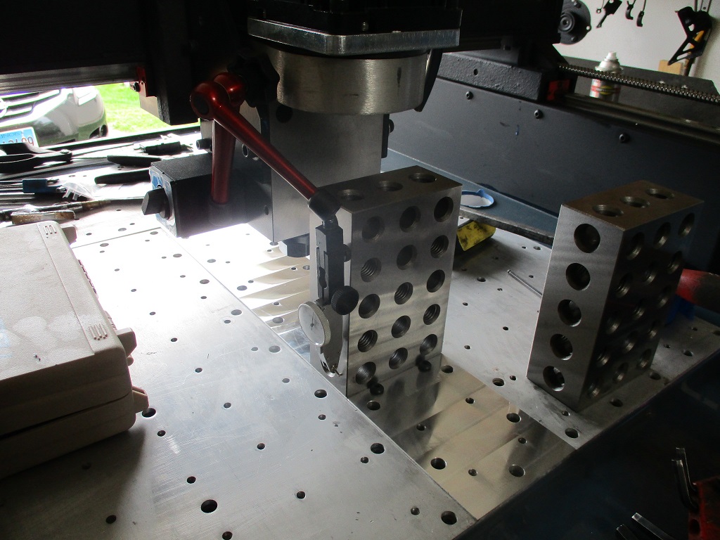
To install the shims, I loosed the 3 large horizontal bolts on the bottom, loosened up 6 of the 8 top bolts to the bearing block - leaving the two on the far left tight, put some tape on the gantry, then used my prybar to raise the right side to slide in the shim, rerun the indicator, add/remove shims, until it was within 0.0005" across 5.5". Then I pushed the spindle carriage to the rear and tightened up the loosened bolts.
Then I turned the 2x4x6 block 90 degrees and ran the indicator up and down the front. I needed to bring the bottom out and the long horizontal bolts were already loose, so I added more tape to the gantry face, pried the bottom out to added shims to the bearing/block face. Rerun the indicator, add/remove shims to get within 0.0005" over 5.5". I do think my Z rails are bowed as the ends of the block are super close, but in the center about 1-2" from the limit switch it is out a couple thou. I tried both blocks and several surfaces and got the same result.
Then I put the 2x4x6 block on its back and pulled out my 5" tram tool and zero’d it. I took the side plates off and drilled and tapped three 1/4-20 holes on each side. The holes are 3/4" from the back of the plate. The two bottom ones are 1/4" from the bottom of the plate and 1/4" below the top of the spindle block. The top hole is 2" from the middle hole.
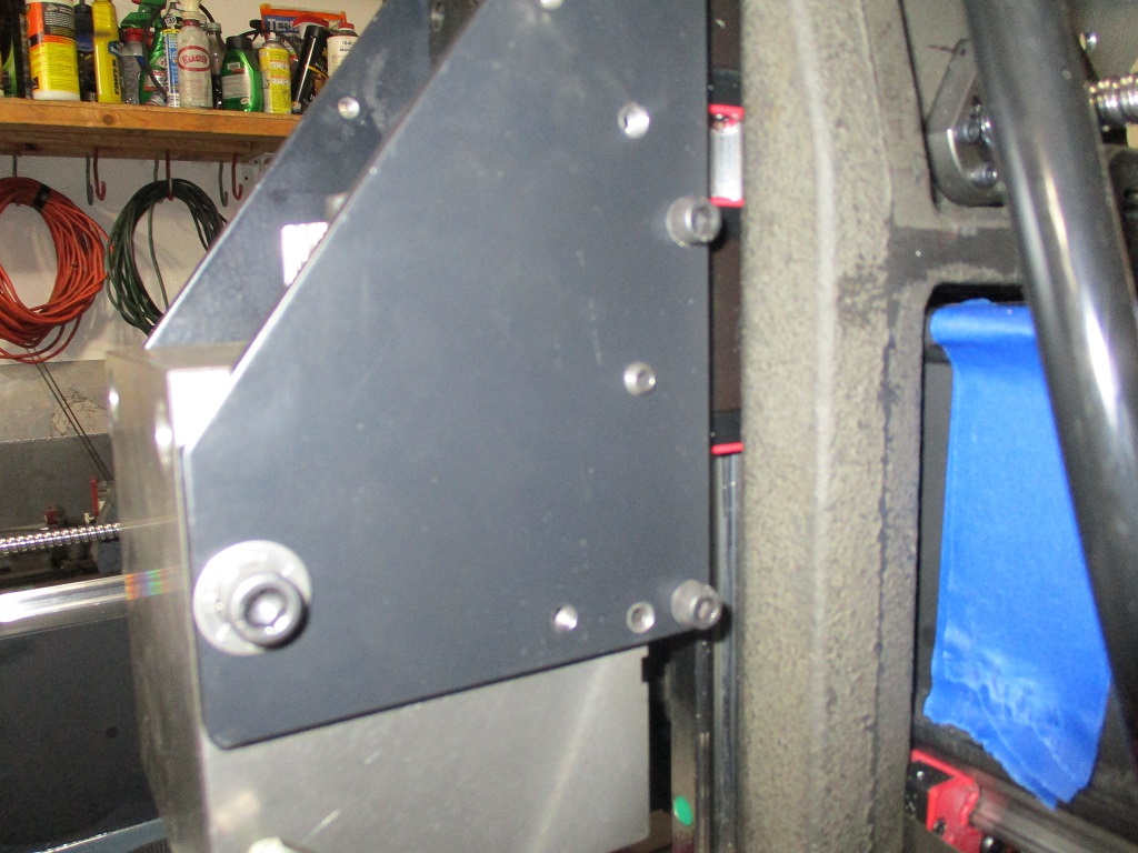
With the side set screws, I was able to loosen the two 1/2" bolts on the back, the front bolts through the plate, and use the 4 set screws to jack the spindle so it was level side to side (within 0.0005" over 5") after tightening all the bolts.
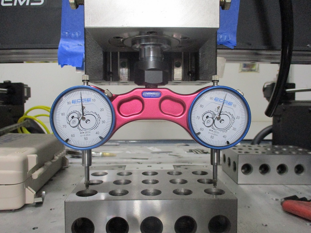
Then I spun the block and tram tool 90 degrees just to check… expecting it to be good to go (machined block, on machined plate…). But it was out too. The top of the spindle block needed to come away from the back. At that point, I decided to take off the motor and offset housing so I could have better access to the back of the block to install some shims. Some trial and error, but able to tighten everthing back down and get within 0.0005" over 5".
Now of course when I installed the block shims to address the front/back spindle tram, it messed up my side to side tram, so I had to go back and do that again… but it was super easy to do the 2nd time.
Probably not going to do it now, but the offset housing to support the motor could be modified to be much stiffer. The casting is attached to the spindle with 3 bolts around the pulley through the wall of the casting - probably 1/4" horizontal thickness - this is where the flex comes from. But then the top plate is attached with several bolts around the perimeter flange that is about 1.25 to 1.5" thick and 4 of those bolts are wider spaced and still above the spindle block. If those tapped holes in the casting around the perimeter were drilled out, then holes could be drilled and tapped into the spindle block, and allow long bolts to pass down through the tall perimeter flange of the casting and be clamped solidly along with perimeter flange. Probably need to spot face the back side of the casting around the 4 bolts and install some machined washers to keep everything flat. But then the offset housing and spindle motor would be very solid to the spindle block.
On Sunday I am planning to surface the remainder of the front of the baseplate and check for any variations along the X and Y axis.
6 Likes
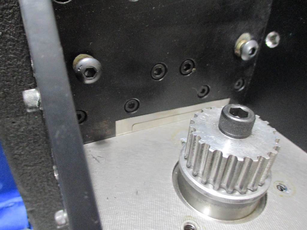
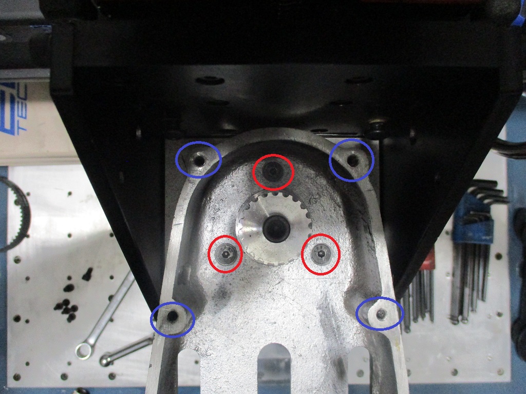
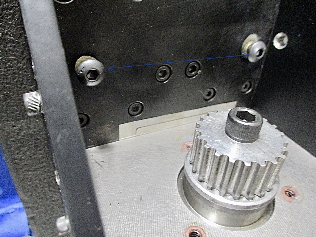
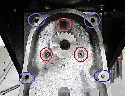
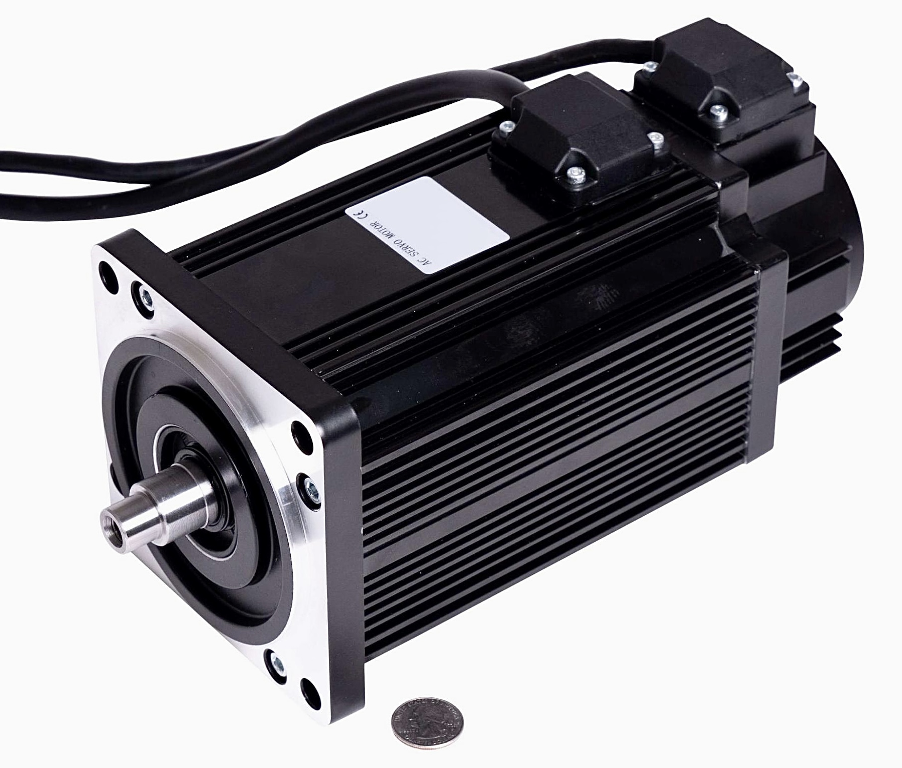
In case I lost anyone talking about the 3 bolts that support the spindle motor offset housing and my proposed upgrade, here is a better picture. The 3 red circled bolts are the only ones attaching the housing and supporting the motor. The 4 blue circled holes are the ones I propose to drill out and tap the spindle block to attach them. This will change the sequence of installing the top plate for the offset housing, but everything could still go together as planned.
I am about 90% done surfacing the front of base plate. There are still 2 low spots in the front left and rear right.
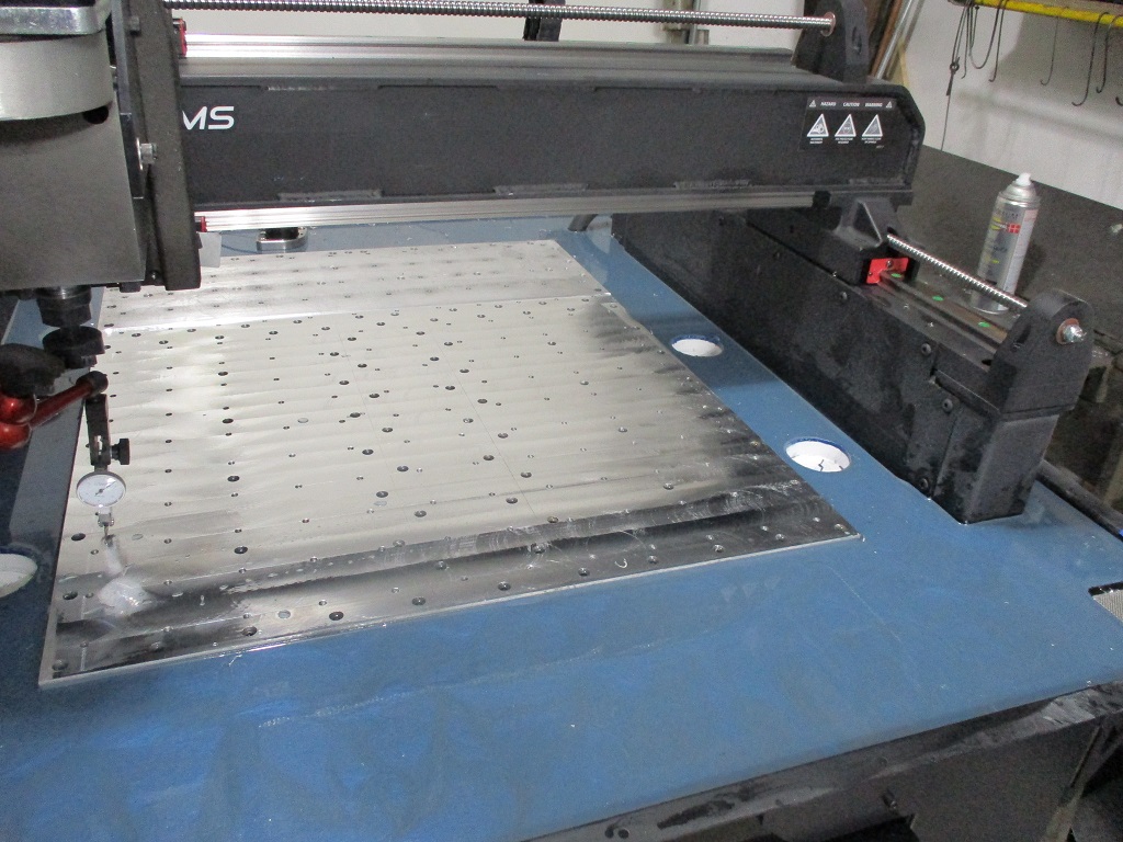
This was a worn spot in the Langmuir plate and not all of this will clean up, but anything past the 1/4-20 mounting holes will not matter anyway.
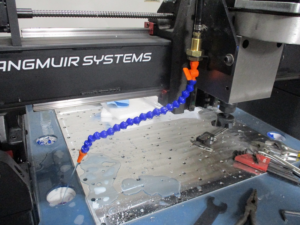
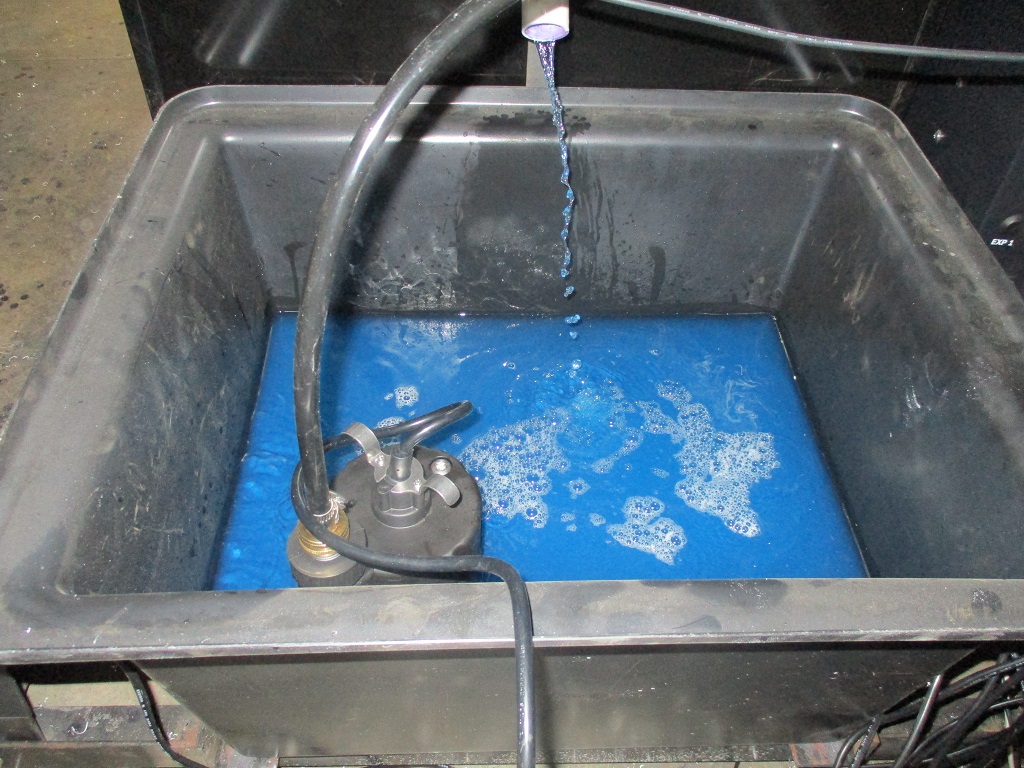
I wanted to have the flood coolant operational for the finish passes so I took some time today to get everything hooked up and mixed up about 5 gallons of the fusion coolant.
4 Likes
I’m definitely with you on this.
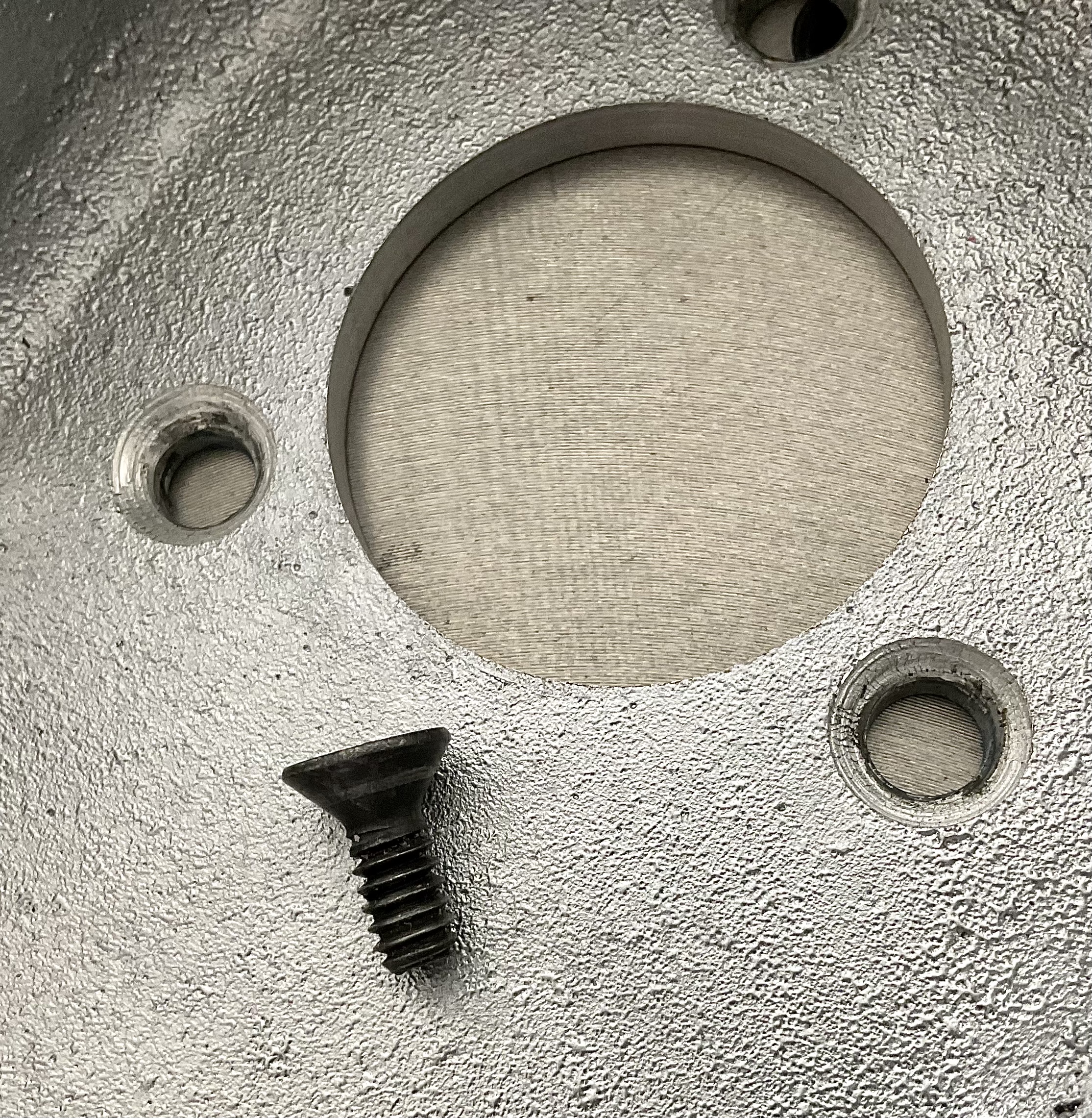
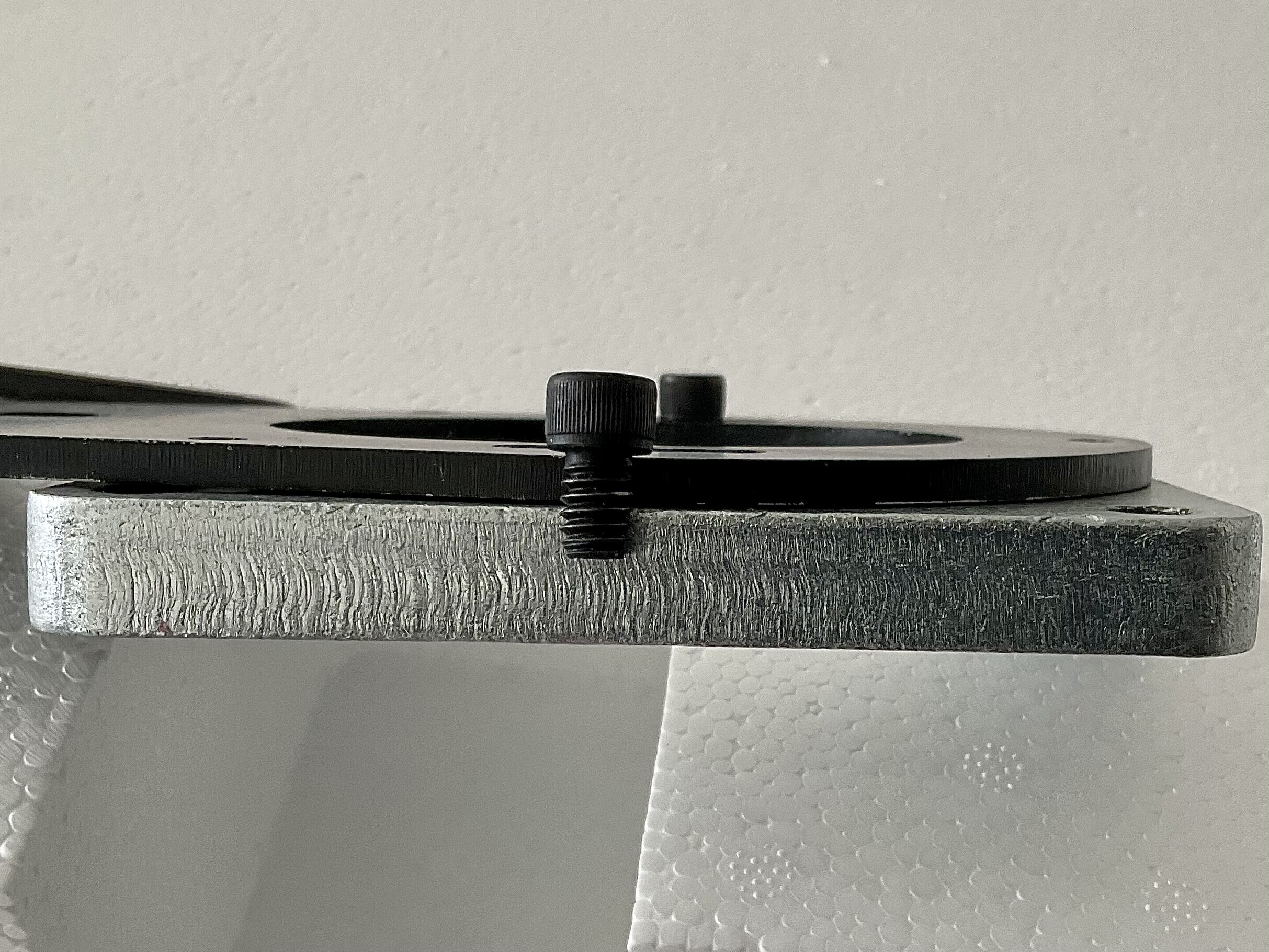
Around the threads I had some high spots that needed to be flattened and chamfered slightly.
Also these button head screws are 1/4-20 and the heads are not much larger than holes in the spindle housing. There’s more than enough room in the housing for 5/16” cap screws to fit if you were to drill and tap the backplate for 5/16th threads. That would make them the same diameter screws as the other two.
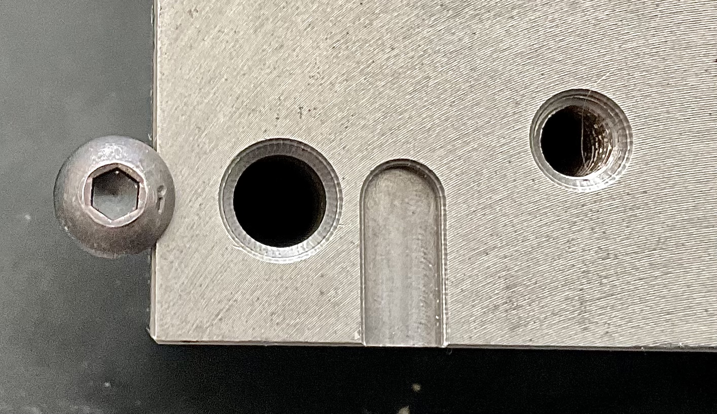
The pulley housing was not machine chamfered for the 3/16” screws. As cast there is only a radius to the hole so there is limited contact as seen by the wear mark on the screw. A light clean up with a proper countersink would improve contact a lot.
Good idea for the outside screws. I was planning to drill and tap for 3 additional screws but I’ll probably do your suggestion as well.
I also discovered recently that the pulleys can be swapped should anyone want to run the spindle at 1/2 speed for an application requiring maximum torque.
2 Likes
How true are the pulleys? Because regardless of the half baked belt drive assembly design, I think the majority of the cyclical vibration produced by my machine is caused by inconsistent belt tension.
I assume the pulleys are on keyways and can’t by adjusted but if they can it’s worth seeing if they can be centered.
Sorry, no keyways. The regular Nema 43 servos I’ve observed come with 19mm keyed output shafts.
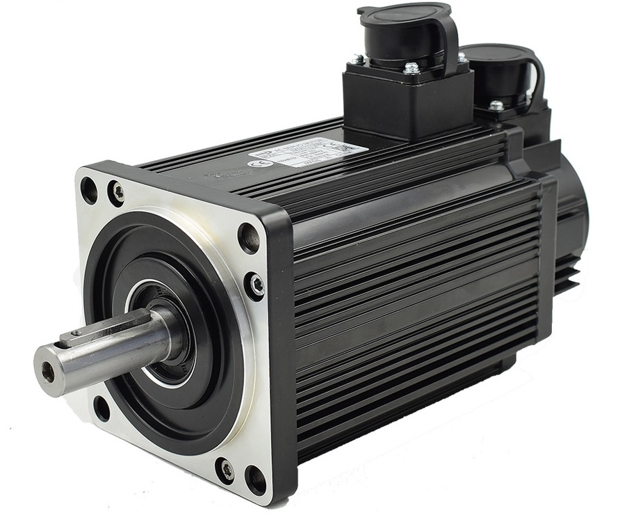
For whatever reason, the MR-1 servo is reduced to 14mm dia. The pulleys fit well but will spin freely without the 5/16th cap screws holding them in place.
As I already mentioned in another thread, the adjustment plate could use slightly longer screws. 1/4-20 x 1/2” and a couple washers.
2 Likes
The CNC machine that I am waiting for uses Masso G3 Touch controller and closed loop steppers.
I got the front of the baseplate to where I am happy with it, so I flipped the X-axis 180 degrees to start working on the extended area. Had to pull all the cables from the cable control paths, but they all reached w/o pulling them from the conduit which is good. Sucks to have to go through all the tilt/nod/tram work another 2 times… but that is what it takes.
1 Like
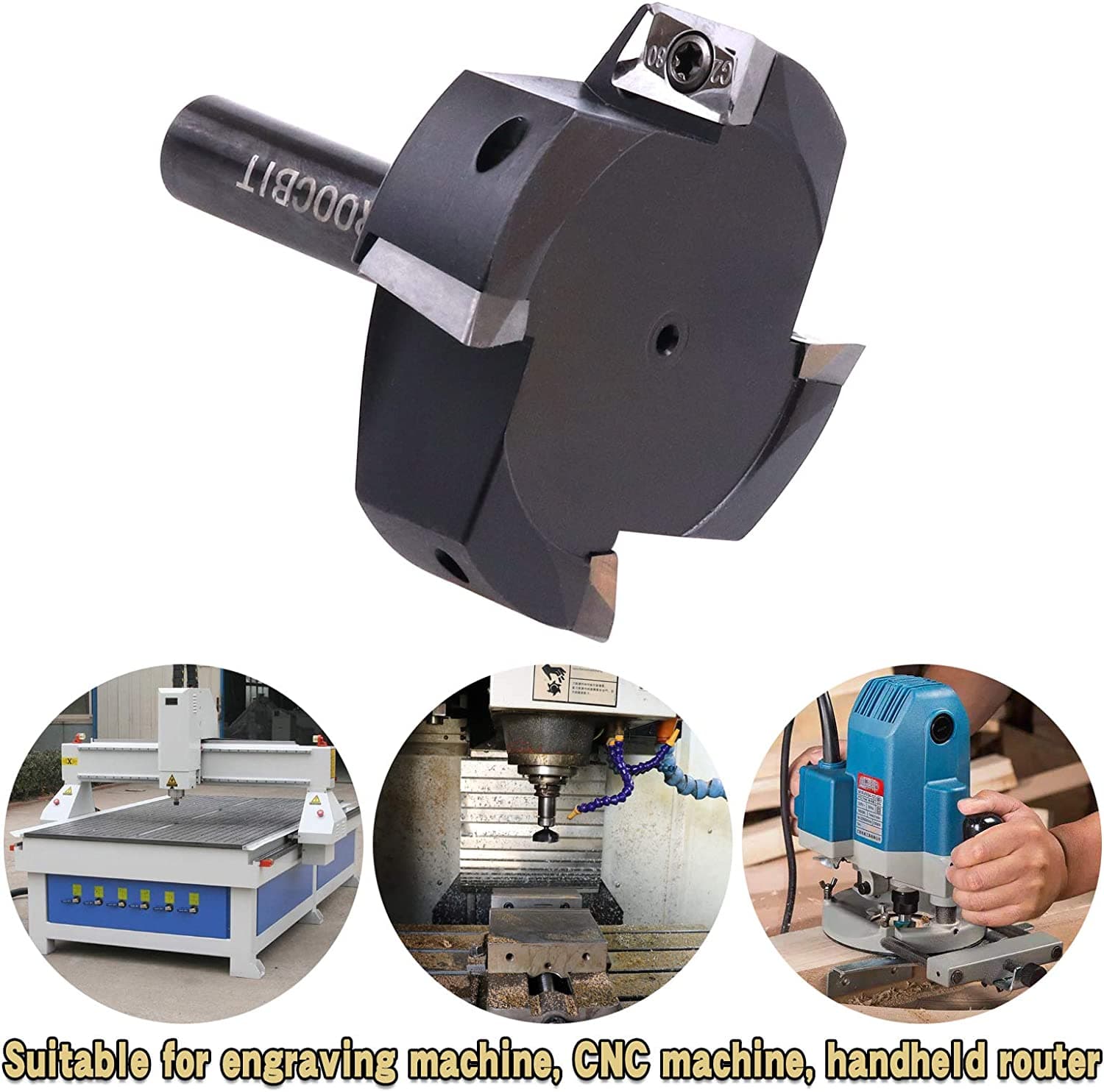
Took about 0.045" off the thicker rear plate and still have about .020 - .030" left to go. Also trying out a new 2.5" cutter with 4 inserts. I still need to do all the alignment work, but from what I am seeing, it is still pretty close. I will measure it tomorrow and see how close it is and if I want to mess with it further.
1 Like
Pics of the cutter please
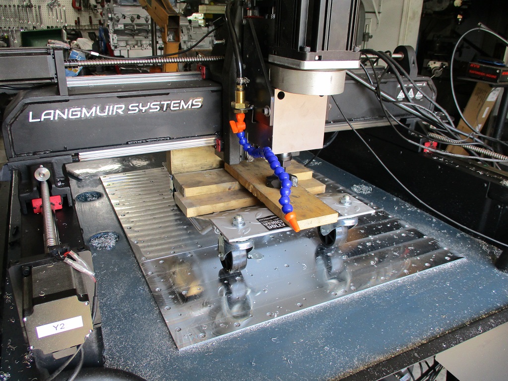
The baseplate is now fully surfaced and the X-axis is back in the proper orientation. Some things I learned… don’t be surprised to see around .005" difference between the X-carriage and the baseplate when you flip it due to some tolerance stacking. I used some of the shims to true it up so the front and rear baseplates would be parallel with each other.
I forget who posted it originally, but the wheel dolly worked great. The 3/16" spacers came in handy as I could pull them out and then the X/Z-axes would rest on the dolly and clear the Y-rail carriages
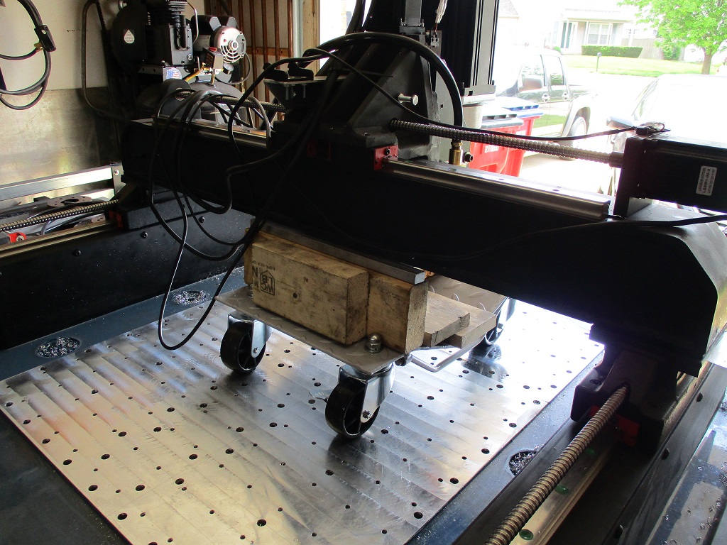
By using the flycutter I was able to surface about 1 1/4" of the rear baseplate within the machine travel before flipping the X-axis.
The one regret with all my mockup before concrete, I didn’t install the Z-axis to verify where the spindle ended up along the Y-axis. With the flycutter, I could have easily made the baseplate 32 " and used this space at the front.
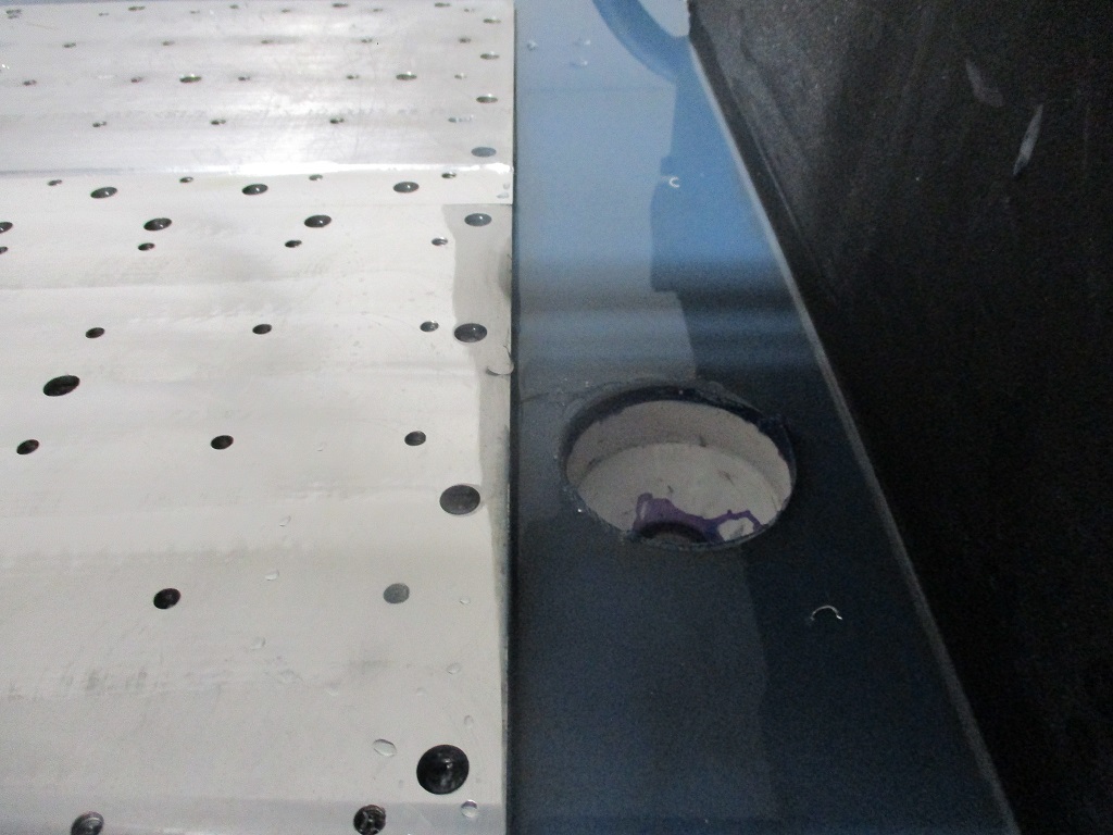
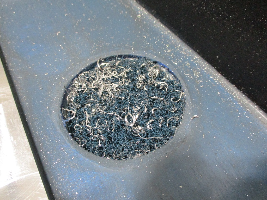
For the 2 center drains, I used some thick & coarse scotchbrite to ace as a filter. Just cut them in slightly oversized circles and pressed them into place.
Now I get to work on the enclosure and lights.
4 Likes
If you had to do it over again, would you surface the rear section first?
BrianS, that is a good question. If I had to do it over, I think I would have still surfaced the front section first. I learned a lot on the front side and doing it first gave me a reference to check against when I did the rear and helped identify the need for shims to make the front/rear parallel. Also, the low points in the plates were all on the front plate, so it was good getting those close, surface the rear about 0.010’ lower and then switching back to the front for the finishing pass. I used a Z step down of 0.0005" when I was close to matching the front to the rear.
2 Likes
I just poured the concrete on my MR1 yesterday and started a pond cure today. My question is how long after you end the wet cure is it safe to do the epoxy. Epoxy traditionally doesn’t like moist surfaces. Thanks,
Sidon
Once I use towels to end the pond cure and remove the excess water, I waited about 7 days before doing the epoxy.
Thanks,
Sbdon
I like what you have done for the drag chains. Looks real sharp
I have been slacking on the MR-1 build… I did move it to its home, leveled it again, started adding the enclosure, lights and cut some of the OSB from the MR-1 crate to fit the top of the enclosure.
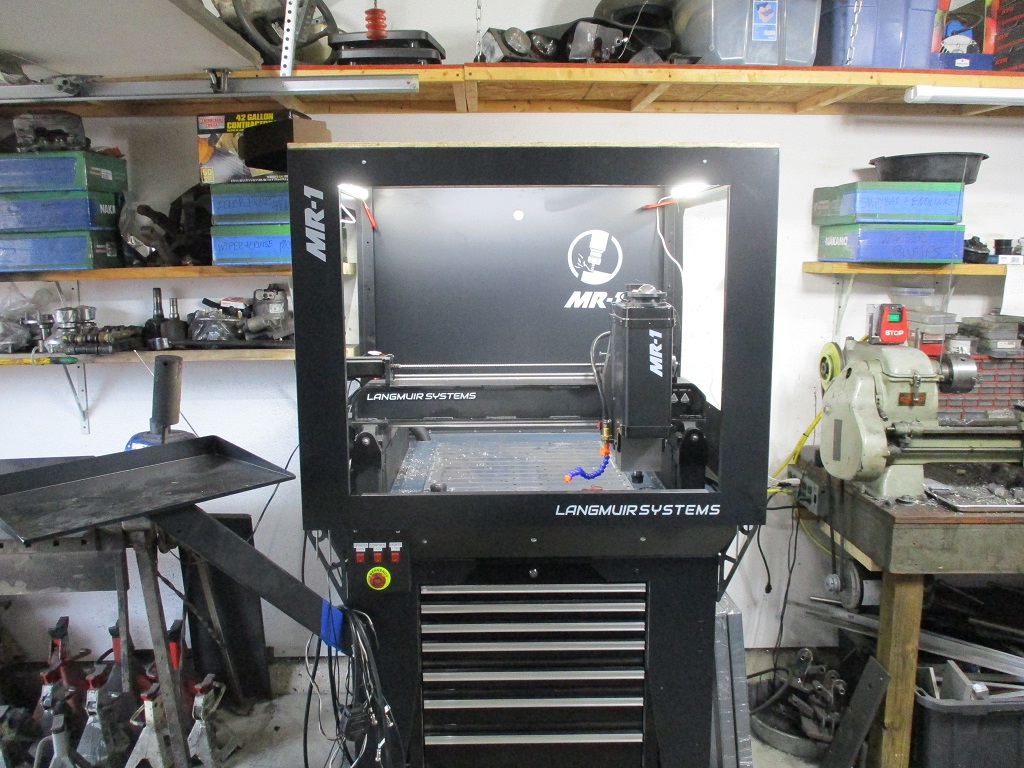
Still pondering the air and coolant wash routing inside the enclosure as well as the door setup.
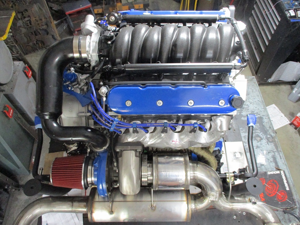
This is what I have been distracted with:
4 Likes