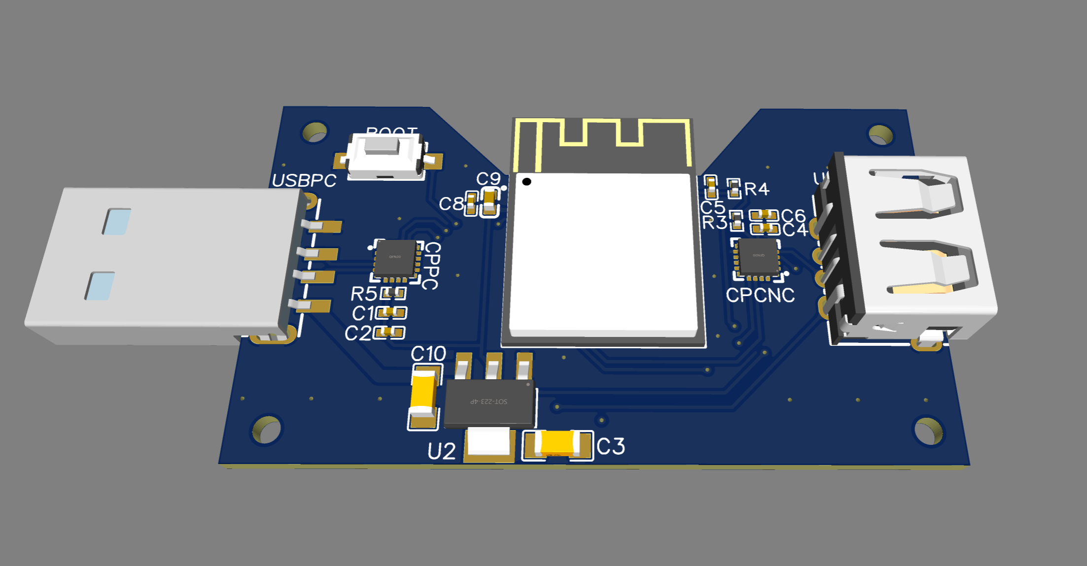
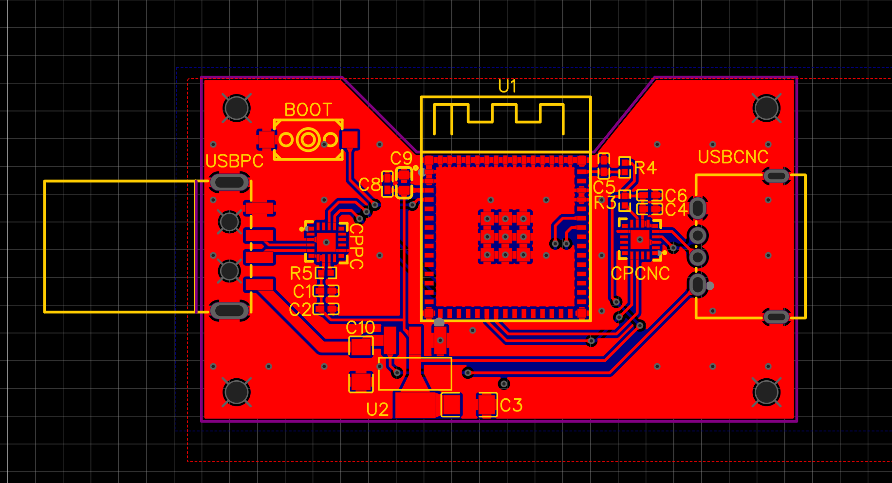
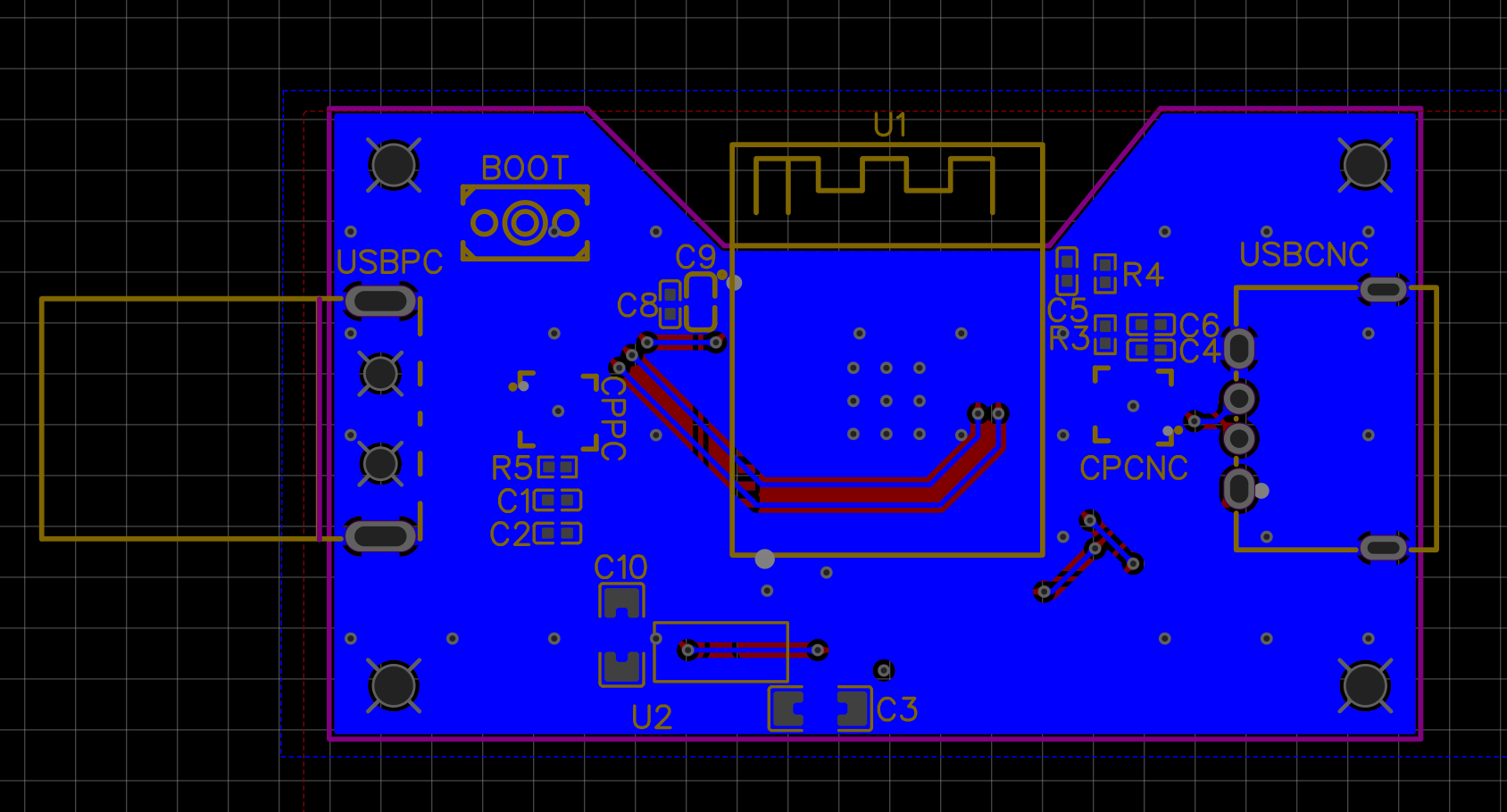
I’m in the process of building a wireless jog controller. The design will consist of two elements. The first one will be a usb device that will sit between the pc and the cnc controller. It will proxy the grbl commands and events from the pc and the controller. The second unit will be the actual jog controller. They will communicate over BLE. I plan to add two 4 pos rotary switches. One will control the axis to be jogged, while the other will control the jogging speed. It will have a screen that will show the current X,Y,Z positions and the current selected axis. It will also include a big rotary dial for jogging and an emergency stop button. I will appreciate any ideas for adding any other features to the remote. I will be posting updates as I progress. The following image shows the pcb design for the usb proxy which is currently in production. I might add a usb isolation circuitry to it in the future.
You must be bored to death. The regular unit from Langmuir works perfectly. I’ll be interested to see how it turns out. I don’t believe EMI will be a problem unless you have a Tig welder or plasma unit running simultaneously. Now, the 5v signal from the computer USB to the control board may be an issue.
Don’t know till you try. Give it Hell, @intacto

Yeah, I’m in early retirement and literally bored to death ![]() What kind of a problem can the 5V USB bus cause? It will not be any different than connecting the pc to the controller with a usb cable which carries the 5V signal.
What kind of a problem can the 5V USB bus cause? It will not be any different than connecting the pc to the controller with a usb cable which carries the 5V signal.
5v signal from the USB runs the control section of that Langmuirs board. I worry that your device will rob some of the voltage and make the board do crazy things. Now, if it is self-powered, that may not be an issue. I’m just thinking out loud here.
")
This thing is a self-powered isolated device for a USB. It maintains the correct 5V signal.
It might be a help to you if, in fact, there is an issue.
Hell, you got this. Could you keep us posted?
Every time I see one of your posts, I smile ![]() .
.
Actually I didn’t check if the arduino inside the controller is powered over the usb 5v bus yet, but even if that’s the case the circuity inside the proxy device will be consuming 120ma on average. I added a bunch of decoupling capacitors where needed so hopefully it won’t cause any issues. But I might end up adding some circuitry to utilize an external power supply like in the video you shared. I will keep posting as I progress and will be providing all the schematics, gerber files, stl files and BOM when things start to shape up.
Your ESP8266 choice is excellent. If you want a quick design review before sending off boards, let me know.
Pardon my ignorance, but is there some “feedback” of position from the controller to the PC? Obviously there is no actual feedback since we have open loop motors. I can’t see how you could manage having two input devices otherwise, so I must be missing something.
Would love to hear any feedback. I will be sharing the schematics in a few hours. It’s actually esp32-s3-mini-1 but you know they are basically the same.
I have already both analyzed the packets between the controller and the pc and also decompiled the cutcontrol software. The controller machine is sending packets with work coordinates on every movement. Open loop control will just cause missed steps to be ignored during machining.
I’ve done designs with both 8266 and 32.
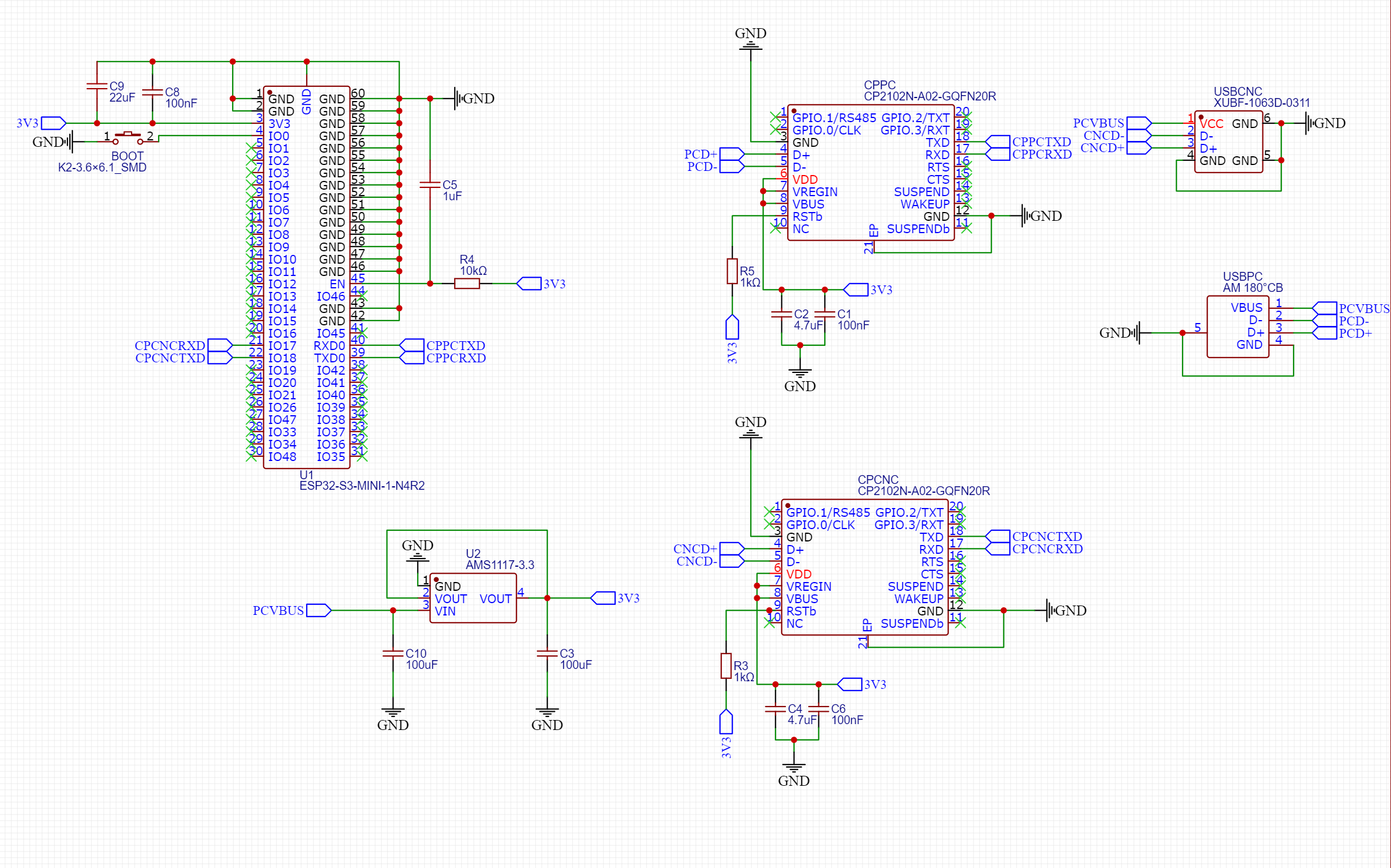
Schematics is as following, It basically has an esp32, two cp2102 for serial to usb and usb to serial conversion (input & output) and a voltage regulator. The jog controller (pendant) will communicate with this device over ble (or maybe esp-now).
Having a jog wheel pendant like a “real” machine would be fantastic!
My general circuit design considerations
-
add 1.5K from USB D+ to 3V3, this tells the host that this is a full-speed device when plugged in.
-
Add a single thru hole test point to GND. If you need to debug your circuit with a scope, solder a pin to this hole for your scope ground.
-
add test points for 3V3 and all your logic level serial lines.
-
Add a top silk rectangle for marking board ‘serial number’. This is handy to identify which board is which when debugging or flashing.
-
add board revision, date (I use YYMMDD) and your name to top side silk
-
add an LED to a CPU output pin to check that your board is actually working using only blink.ino.
-
consider adding LEDs to all logic-level serial RX/TX lines. Handy for debugging.
-
remember its better to put down footprints for LEDs, switches, spare I/O connectors and mark as DNP. For example, I always add a I2C 4 pin 0.1" header to every board if there’s spare CPU pins. I also add SPI header if there’s pins. You may want to use your board for future projects.

Specific questions.
A. I don’t know what the MR1 uses for USB. When you plug this board into a PC, it will get enumerated as a serial port. Is this what you want? Or do you want it show up as a USB HID device (keyboard)?
B. Add a reset switch from EN to ground.
C. add ESD protection to USB D+ and D- lines. see
Other than that, I checked that you had the QFN20 pad connected to GND. Make sure to run all the ERC and DRC checks.
Where are you having these made? PCBWAY, JLCPCB? Good luck.
I use CP2110 on my boards and was at some point going to try to build a controller, more for the puroose of sending XY, touch metal to set Z0, raise Z to __ then have a torch on - delay time - torch off via a mosfet/optofet. Goal is highly refined center punch/peck with per instance precision z height control, precise torch on off times.
Have you determined baud, handshake protocol to connect to the controller from your silabs and then the method to send g code packets format? How easy is communication?
You should have diode protection on all usb connectors > cp2102 io. You should also put ferrite beads on the 5v from usb + to Vbus. Run the micro from a separate 5v>3v3 analog LDO.
I add a piezo buzzer to most boards, you can drive them well enough to hear either direct or use 2n3904 to drive it. Buzzers are valuable for debugging/show breakpoints, or alerts and troubleshooting feedback. Takes up space though so you could add pads to add external buzzers. As noted a 4 pin kk molex header with 2 wires pulled up with 4.7k, 5v and gnd then you can add a $4 i2c LCD for debugging and troubleshooting. GPIO from silabs chip to your uC for reboot etc if needed. Once you get into it might ss well just add headers to send step and direction and tap into the stepper drivers and home switches!
Thanks for the detailed list of feedback. Here are my notes on your feedbacks.
- add 1.5K from USB D+ to 3V3, this tells the host that this is a full-speed device when plugged in.
- The cp2102n module has that resistor inside it. But the CNC controller side is expecting a baud rate of 115200 bps, so that will be the soft limit I will set on the software side.
-
Add a single thru hole test point to GND. If you need to debug your circuit with a scope, solder a pin to this hole for your scope ground.
-The outer metals of both usb connectors are connected to ground, I usually utilize them for this purpose when needed, but I will be include the hole as it sounds more professional way to do it. -
Add a top silk rectangle for marking board ‘serial number’. This is handy to identify which board is which when debugging or flashing.
-I will include it in the next revision. -
Add a top silk rectangle for marking board ‘serial number’. This is handy to identify which board is which when debugging or flashing.
-I will include it in the next revision. -
add board revision, date (I use YYMMDD) and your name to top side silk
-I will include it in the next revision. -
add an LED to a CPU output pin to check that your board is actually working using only blink.ino.
-
consider adding LEDs to all logic-level serial RX/TX lines. Handy for debugging.
-I skipped adding any optional components to reduce the price even picked almost all the components out of jlcpcb’s basic components list to reduce the price. But you might be right and this could cause some headaches later on. I will include them as well. -
Remember its better to put down footprints for LEDs, switches, spare I/O connectors and mark as DNP. For example, I always add a I2C 4 pin 0.1" header to every board if there’s spare CPU pins. I also add SPI header if there’s pins. You may want to use your board for future projects.
-My drawers are already full with esp and atmega devkits with all the pins availabe as headers. That was the reason for skipping it.
A. I don’t know what the MR1 uses for USB. When you plug this board into a PC, it will get enumerated as a serial port. Is this what you want? Or do you want it show up as a USB HID device (keyboard)?
- That’s exactly what I want. MR-1 currently uses the USB port to communicate with the PC over TTL. This part will proxy this communication send relevant events like position changes and status to the pendant and it will inject packets to this line when the pendant sends an event. I will also utilize the male usb port for debugging and programming the esp.
B. Add a reset switch from EN to ground.
I skipped that as well as I can easily unplug and replug the device for a reset.
C. Add ESD protection to USB D+ and D- lines.
I can’t believe how I forgot that! Thank you so much, I will include a SP0503BAHT on both sides.
Other than that, I checked that you had the QFN20 pad connected to GND. Make sure to run all the ERC and DRC checks.
-Yes, both the center pad and two finger pads are intended to be grounded.
The current design is currently in production at jlcpcb. I expect to receive them next week.
Thank again for taking your time, I really appreciate it.
The communication happens over USB TTL. I made some preliminary tests by cloning the com port on windows with a com port multiplexer. I could both see the packets and inject additional commands. The protocol is mostly human readable, I can share some sample data if you are interested. Also the cutcontrol software is coded in javafx and I gained valuable information about the protocol by decompiling it.
I will include a tvs diode array on the data pins, but I never included a ferrite bead or any other EMI suppressor in my cp2102n implementations. Could you tell me why I need it or point me to a datasheet or reference which recommends it?