Can anyone here confirm if you can test for continuity on the VIM box by measuring resistance across a plug on the DIV input and DIV output?
I ask because I have a THC alarm issue, only to test it and find 0 voltage measured on Firecontrol.
Furthermore, I checked pin 1 and 2 on the plug from the VIM box to the large controller box and it measures 0 volts.
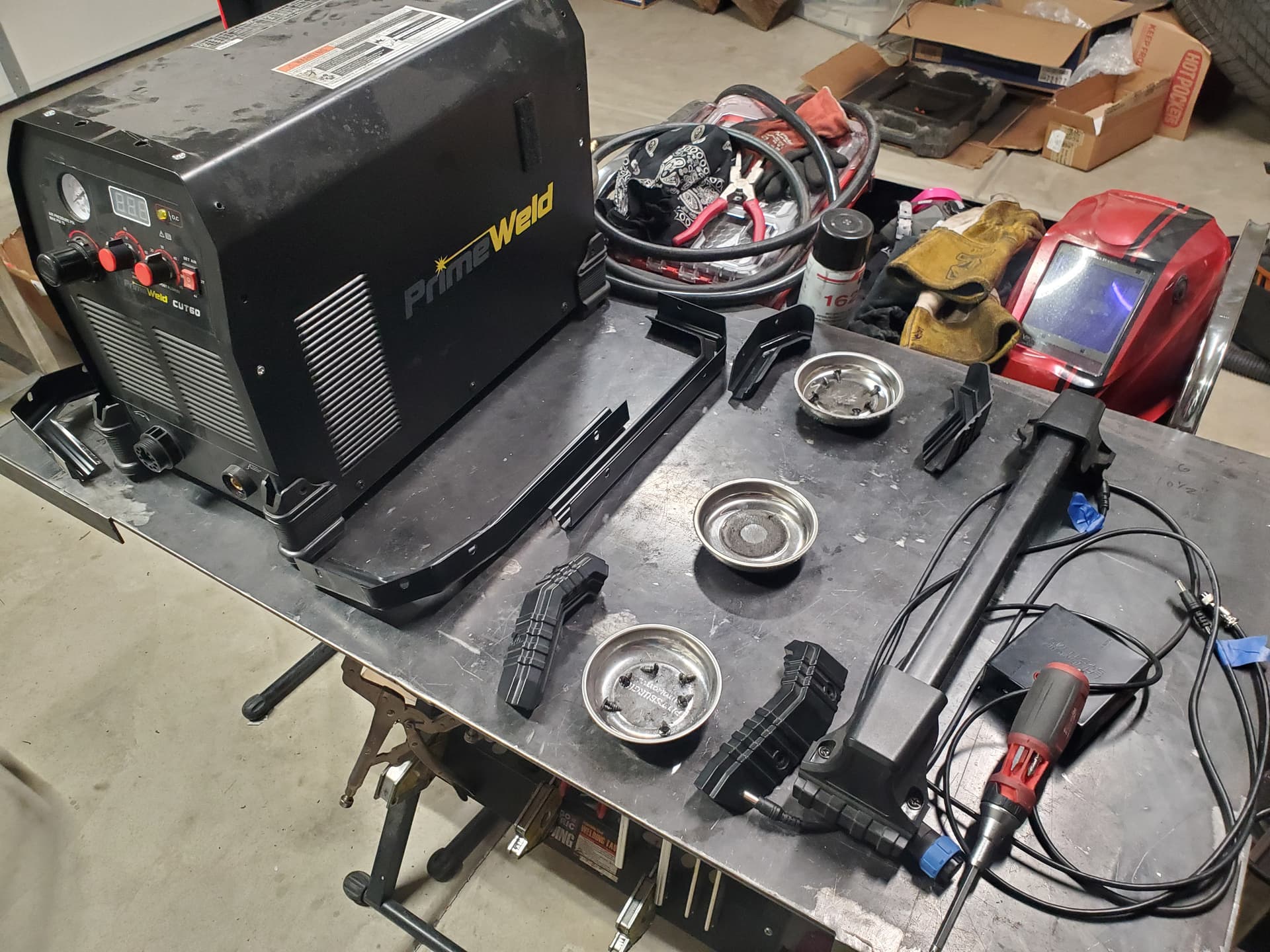
To ensure it wasn’t a “me” issue, I confirmed that I have continuity on my CPC cable as I soldered the correct pins to the appropriate wires from my PrimeWeld CUT60.
No, this is not a new install. Table has been running flawlessly (with one issue last month) for 10 months so it is not a user-install error nor has any single item in my system changed.
All that is left to do is measure voltage divided from my CUT60 itself (I’ll do that Monday) but my other tests showed 0.
Only thing outside of measuring my plasma cutter is confirming the VIM box if it’s good or bad.
I’d test the plasma first, but Primeweld does have a history of voltage spikes from their divided voltage output. Those spikes have fried VIM boxes in the past.
I duct know enough about electronics to answer your question about continuity from DIV input to DIV output.
Well I would but, I’m unsure of both the proper procedure as well as what my voltage readout should be.
I have the ability and understanding of how to do something like this, but I don’t know if simply having Firecontrol fire my torch will cause my CUT60 to output anything through pins 4 and 6.
Or, can I just connect my hand torch, fire the trigger, and will I get a voltage reading on the barrel plug that normally connects to my VIM box?
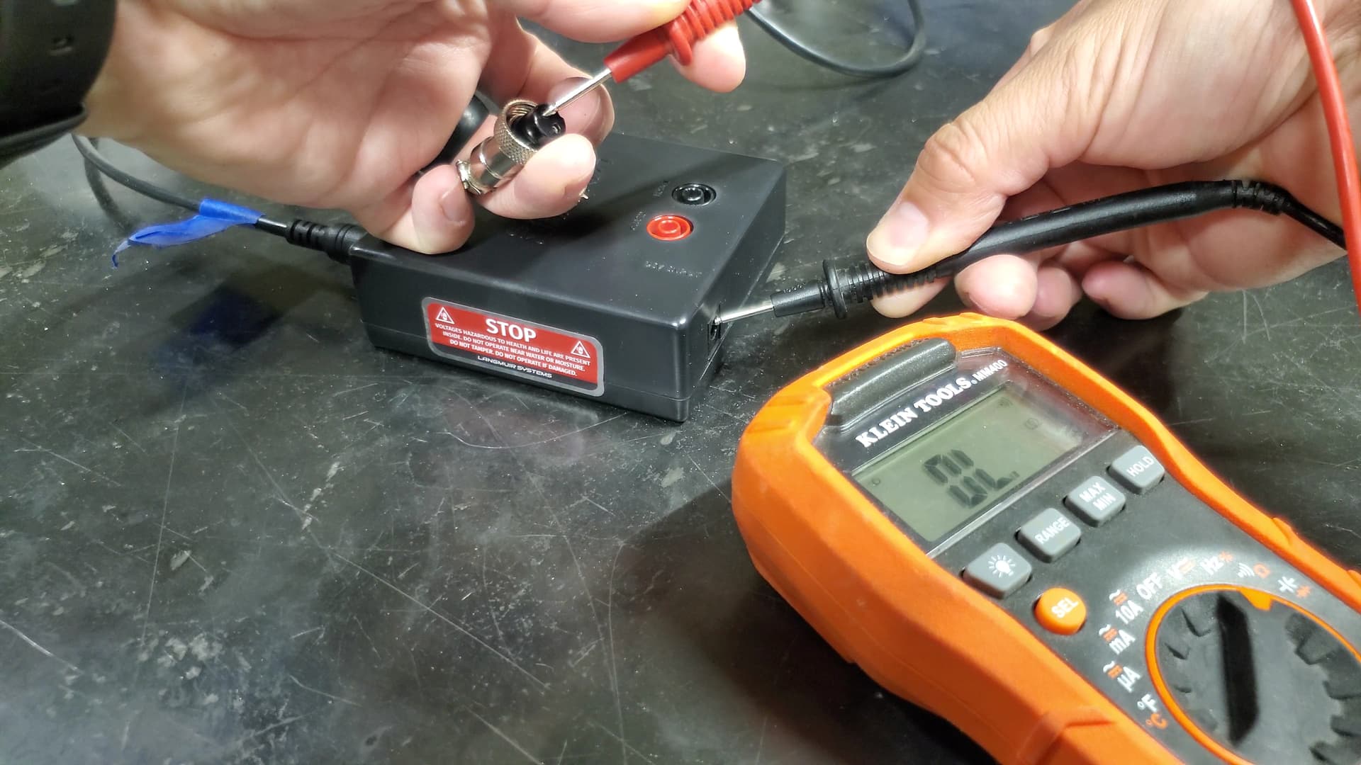
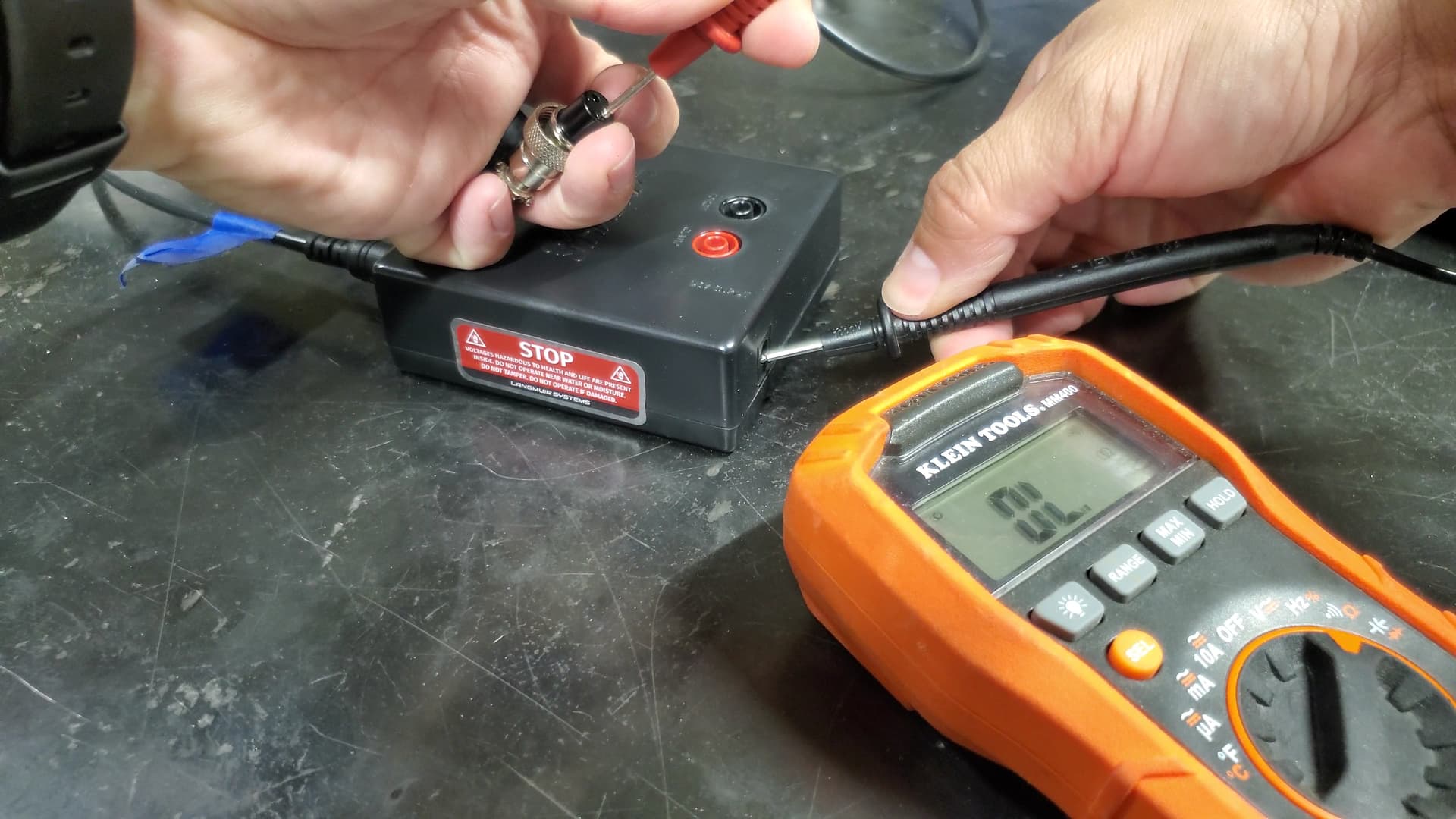
So the easiest thing was to just check continuity and it’s an open circuit.
Thanks for the headsup on voltage spikes, didn’t know that was a thing. But I have read about VIM boxes going bad and an email response from Langmuir was sort of implying that something else may be wrong. Their email response was implying as if I just set my table up…it’s been running for 10 months.
Skip past the chart and there are instructions on how to test for voltage and the expected voltage range at each connection. The 50:1 output should be in the 1.2v to 3v DC range.
You missed where I stated I already did that trouble shooting to verify my cable is correct and I have the correct pins utilized (the table has been running 10 months).
If I rephrase my question regarding procedure, it would be -
How can I properly measure divided voltage directly from my machine if my CPC cable is unplugged to measure the pins? The only possible way to measure the plasma cutter directly would be to actually plug in the CPC plug because it includes the barrel plug for torch ON/OFF if I’m using Firecontrol to do a straight line cut.
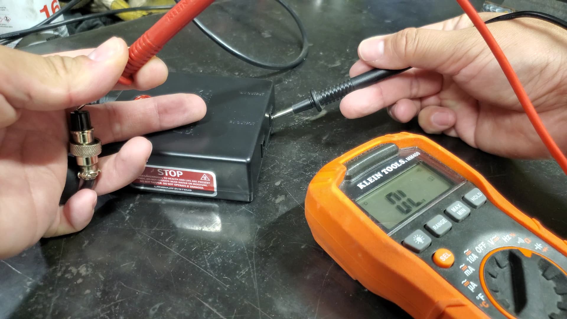
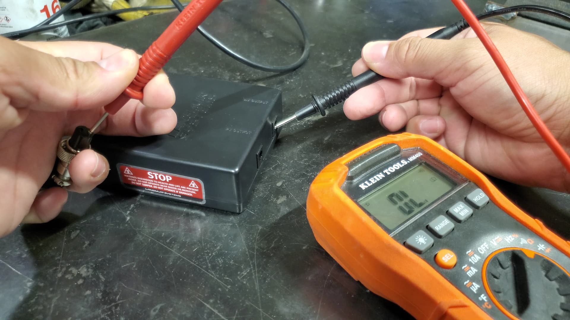
So following up with that, would it be appropriate to just measure from the barrel plug that goes into the DIV input on the VIM box? Because if so, I already did do that and received 0 volts.
If you have tested the cable for continuity and you’re not getting voltage at the barrel connector, then your machine is not sending voltage through the divided voltage pins.
I will check my VIM for continuity when I get home in about 30 minutes.
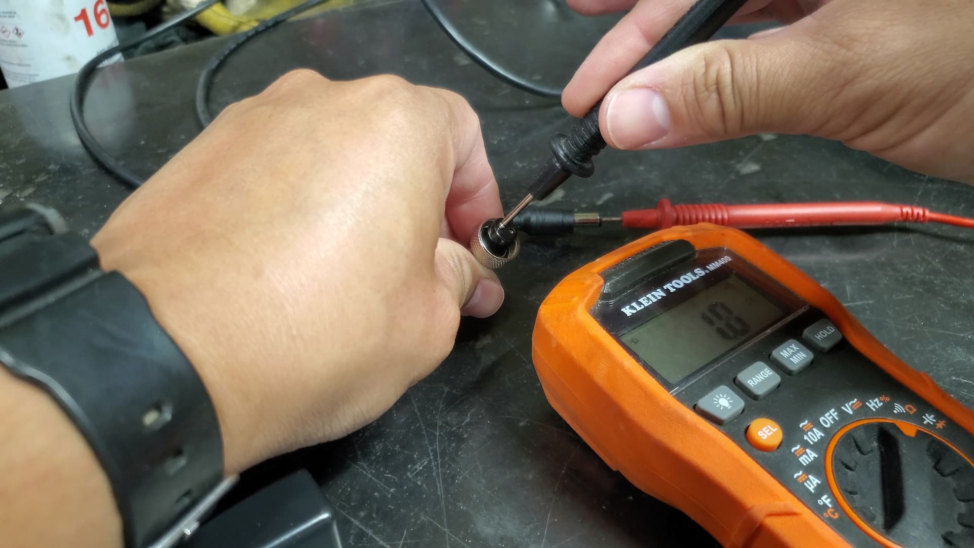
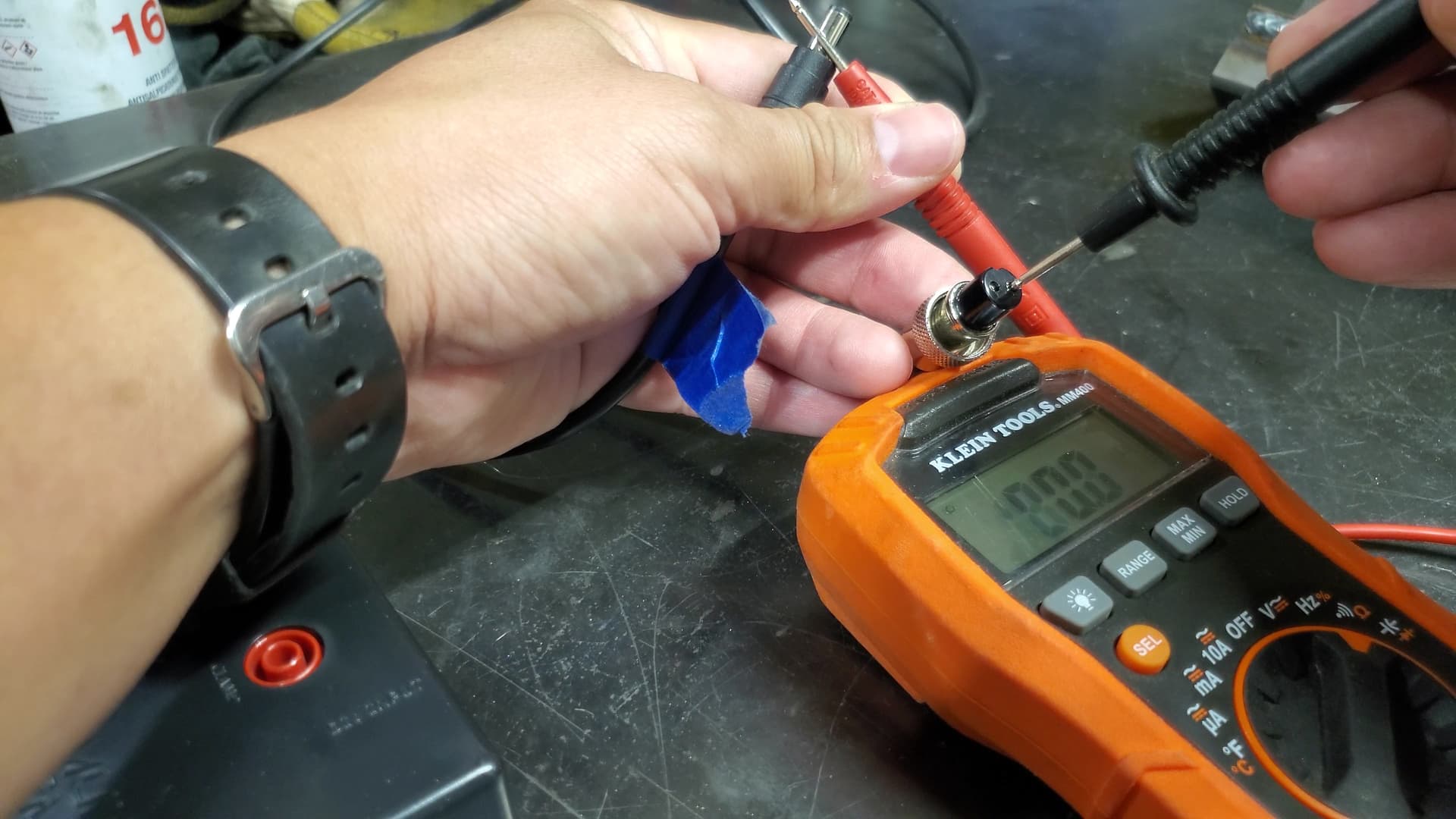
I tested my VIM with a multimeter between the DIV input and DIV output and get a small amount of needle movement between the center pins. Between the contacts that touch the outer barrel, the needle is pegged for continuity.
Inside the ports, there is a center pin and a flat spring that would contact the outside surface of a barrel connector.
It shows good continuity between the DIV input port and the DIV output port on the VIM when I put the probes on the flat contacts that touches the outside of the barrel.
When I put the probes on the center pins of each port, I get a much lower reading. I assume that is from the circuit that further reduces the input voltage.
You confirmed my initial suspicions of a bad VIM box.
Thank you very much!
Langmuir’s response was implying the most basic of things which…I had already covered in my initial inquiry with them but I understand, they have to check in the boxes.
Good cables, bad box so again thanks for confirming @ds690
I’ll be in touch with PrimeWeld tomorrow as well to see if there is a way to “jump” start my plasma cutter and test voltage being output in any other way versus how I tested it myself
Here’s my concern though as I didn’t notice anything burnt on the raw side; it should be perfect really because it’s on its own circuit but why does it not pass a continuity test?
On those particular terminals, mine is showing “no connectivity” as well. Those are not the terminals that I use but just verifying that may be the correct finding.
Guess my question is, specifically to CUT60 owners, is why do they tap for raw voltage into their machine when pins 5 and 7 provide it at the CPC port?
Only reason why I won’t utilize said port is because I already soldered 4 and 6 for divided voltage. That plug stays taped up as I do not want to go through the pain of taking it apart especially with the 7 different layers of heatshrink I added.