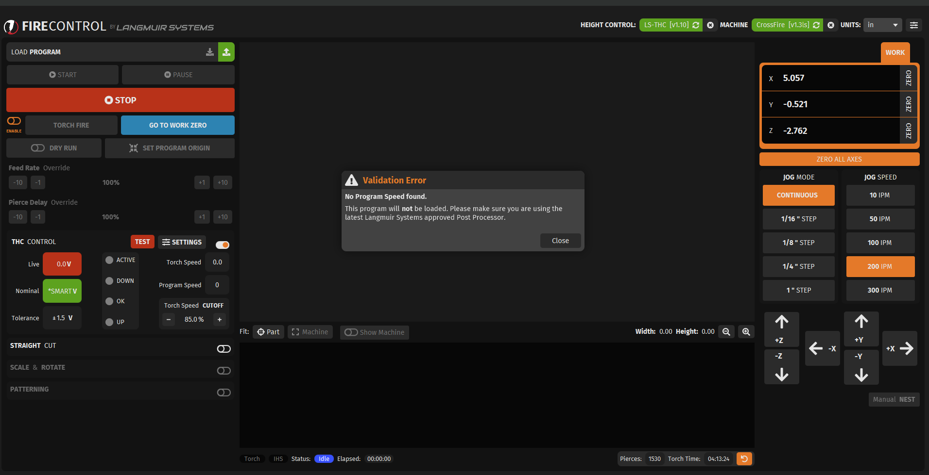
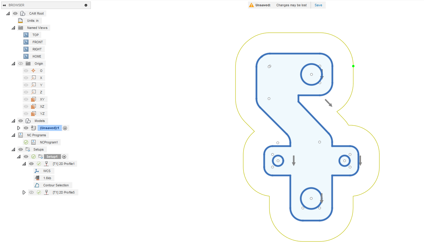
Hopefully the screenshots and NC file are readable. This problem just popped last friday. I read several other posts but couldn’t figure out a fix for it. Things I noticed are the arrows used to all be right next to the lines that were chosen to cut, now they are way outside them. I believe the post processor version 1.6 and fire control V1.3 are correct. I don’t remember it ever outlining the bubble around the perimiter in yellow. Everything has been working fine for the last year.
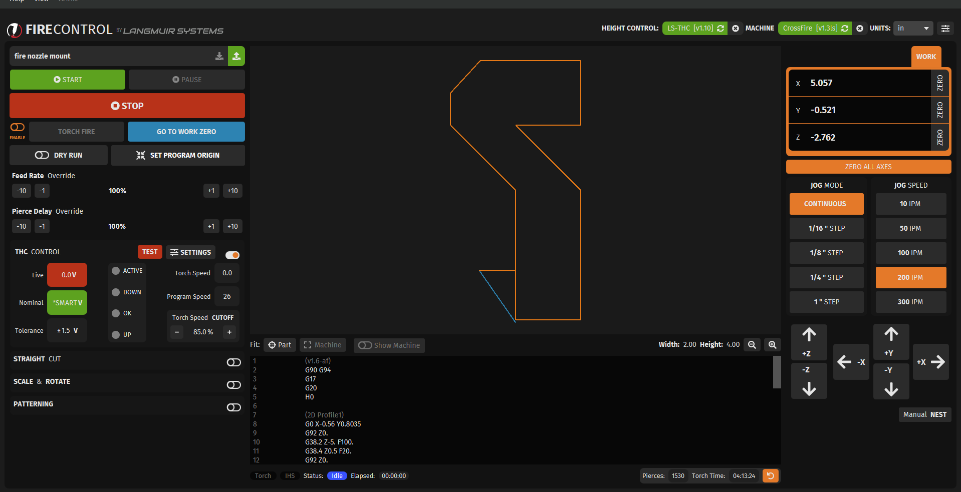
The error of “No Program Speed Found” will happen if no contour was actually picked. If you look at the gcode file it might show that there is actually no cutting that is being instructed. (Edit: I just looked at your gcode file and I am not seeing anything that is jumping out. I would suggest correcting the issue of the yellow outline and re-CAM and process the gcode.)
Another issue is that the post processor file could be corrupted. In that case, dump the current one and re-load from the download section of the Langmuir support page.
As far as the yellow outline in Fusion 360 Manufacturing space, it looks as if your “tool” in fusion is set with a really large kerf width. It is showing the path of the center of that tool and it is omitting lots of the detail of your object.
I’ve tried resetting defaults, no change, I’ve rebuilt the part in a new window, selected all the cut lines. It loaded this time but without the 2 holes that need cut in the part. My nozzle is set at .06", kerf 1" and is set that way in all the other tool paths. I changed the kerf to .6" in this one.
What’s odd is everything was fine and then all of a sudden i have this problem. It’s like i clicked or changed a setting somewhere but i have no idea where.
Kerf should be .06" or less. That is what determines if your cut can fit within the design. The CAM offsets the torch position by half the width of your kerf setting to set the cut path.
David is right. The nozzle, in Fusion, will give you less fits if you just make it the same as the kerf. The kerf is the one that is messing you up. The kerf is the path burned out by the torch. And your kerf is usually in the range of 0.02 to 0.08. It will get small with thin material and wider with thick material.
Sorry I took so long to get back to you. But rest assured @ds690 knows more about plasma cutting than I will ever know.
Sorry for the late reply, @ChelanJim had the answer. I got the kerf width switched with the nozzle size in the post. Swapped the #'s and it’s working again. Thank you.
Another question, @ChelanJim, @ds690 any chance you know if cutting expanded, flattened metal is possible on the table?
Here is a thread that discussed that. Like BigDaddy I have not tried it but it is tricky and quite hard on your consumables and potentially the torch itself.
So if you are doing it as a hired job, bid accordingly.
Are you talking the .500 x 18ga…small screen or the larger stuff?
If it is the small stuff it’s doable. Keep weights on it because you will want the THC off and it will warp. I did a couple pieces a little while back. If it’s the larger stuff, just mark it with a paint pen and do it by hand.
Some plasma cutters have a setting for doing expanded metal, as they said above, you will all but ruin a set.