Hey all, first post so hopefully this is the correct place!
I have a 3 axis machine similar to an MR1 that came with a router fora spindle, and I purchased (have in hand) a Langmuir spindle + servo kit to replace it with as it’s the most capable that I have seen for my size machine. I mean no disrespect here, just a guy looking for answers, but I received zero literature with the parts, nor did I get any direction when I called Langmuir regarding hook up. What I am trying to achieve is a very simple operation - I just want an on/off button and a knob to adjust the speed. Thats it. But the AC Servo Drive that I received (LSMR1-95-00) does not appear on google, so I have no idea how to hook this thing up. I see langmuir has a youtube video for the electrical enclosure connections, but I need to know whats going on inside. Can someone send pics of the inside so I can see hpw the external connectors are routed to the spindle drive? Also if anyone has any advice how to accomplish my desired operation of the spindle I would very much appreciate it. Again, no need for GCODE control, just a switch and a knob.
If I can’t find support and this turns into a full-on R&D project I may see if I can just return everything but I really don’t what it to come to that as the specs on this thing are amazing! Closed loop servo with high torque at low RPM… sweet! Would love to see it in action.
Thank you for this! I will dig through it later. And yes, I purchased everything from Langmuir direct I just sent an email to support and asked if they would sell it to me by itself. It ran me just under $600 for the Spindle/gearbox, servo motor, the drive, and other hardware.
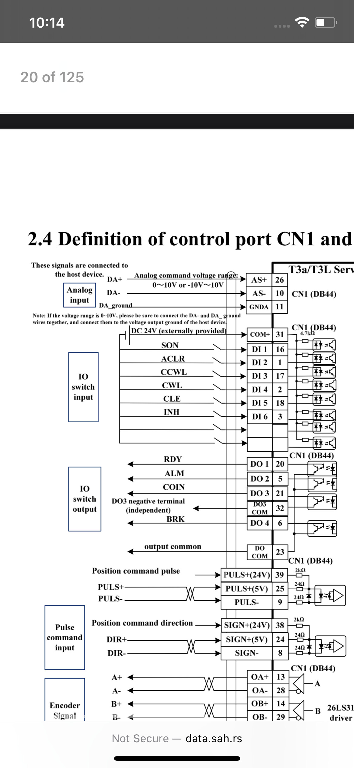
Alex - instead of pin 30, did you by chance mean pin 10? Pin 30 is for the encoder signal output Z- and 10 is for the analog input DA-…. The reason I ask is because I took apart the the DB44 connector and the following 5 pins are used: 10,16,23,26&31. I also noticed on the drive instructions is talks about 0-10v for the analog control? You mentioned 0-5 I believe.
Thanks again! I’m getting really close to firing it up
Oops, yes, it looks like there is a bug in my notes there. Check the original manual (also linked in the notes) to be sure. I do remember finding that you need to connect encoder ground.
I don’t have one of these spindles anymore, so I can’t check my wiring.
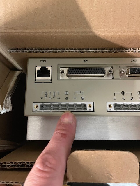
That is odd that the connector from Langmuir does not utilize the encoder ground pin 30… I’m confused as this is slightly over my head. Last question for the time being ~ do you know what connector plugs into this? (See image)
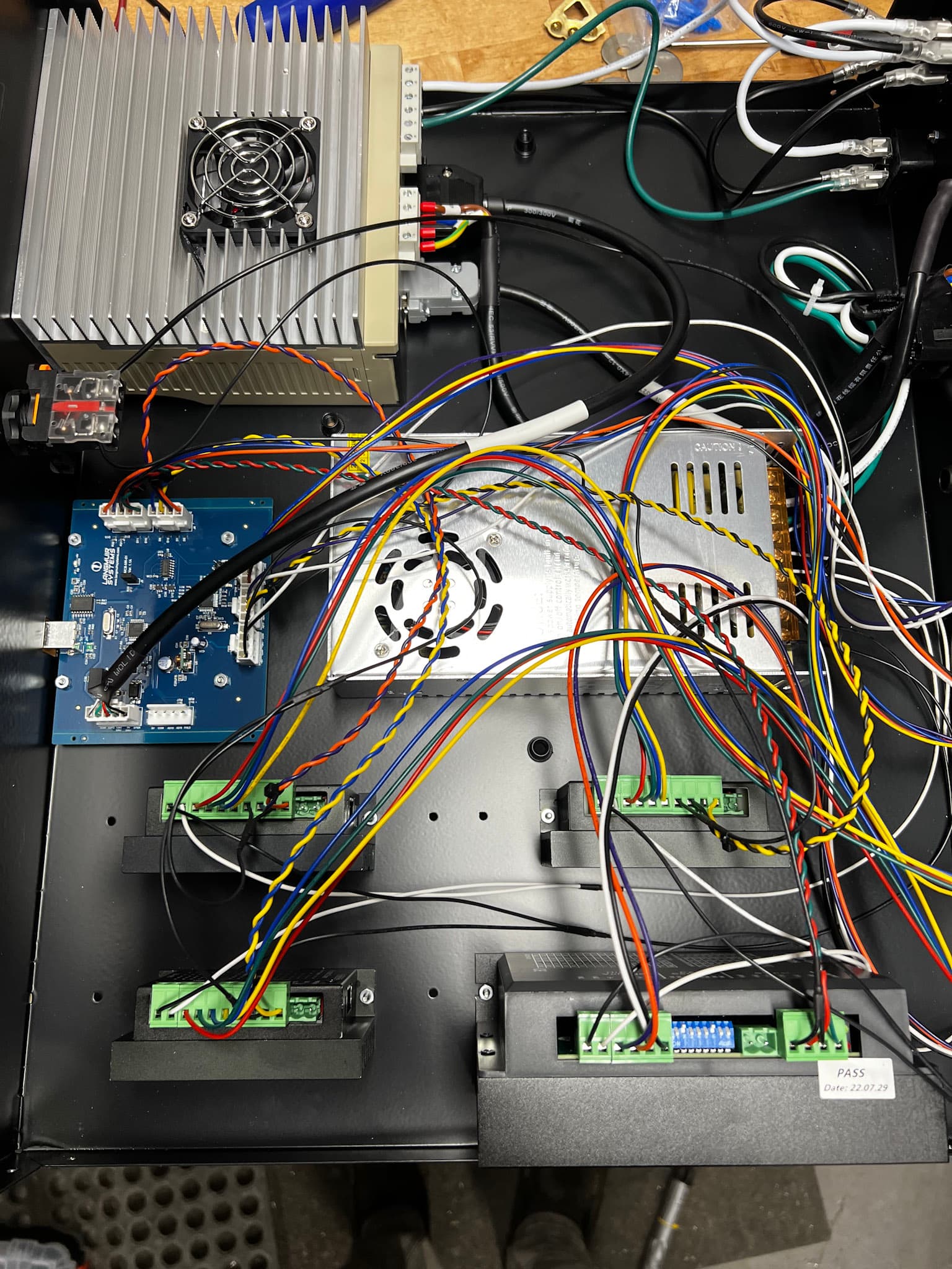
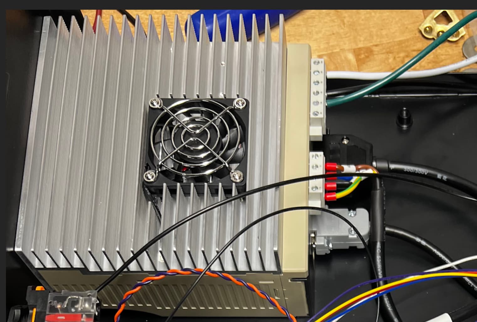
Also, if anybody would be willing to send me pictures of the inside of the MR1 electrical panel, that would be much appreciated… I am interested in how the connections are made between the 4 Spindle motor drive connectors and the rest of the machine.
Thanks again Alex… and my kit did not come with a power chord. So I need to make a cable with a 220v 3 conductor plug on one end and this phoenix style pcb connector on the other.
And the picture confirms that Langmuir is only using 5 pins from the CN1 port… but I know their have been revisions to that harness over time so I’m not sure what are the exact ones used on your machine, but the harness I got uses pins 10,26,31,23 and 16…. The drive instructions rooms say to tie together 10&11 though if your using a 0-10v signal, and then you claim to also ground pin 30… so that’s where I am confused; do I just hook up the 5 pins that my harness uses? Or do I need to add 30 and 11. I’m sure the type of POT I use will make a difference? I wish I knew more about drives!
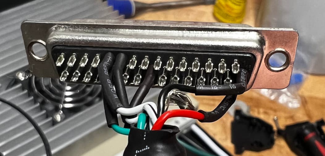
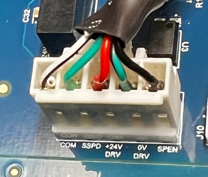
This is what the other end has, note that one of the white/black wires is cut, this is to avoid tying together AC and DC ground (which the MR-1 has floating with respect to each due to the probe design). Langmuir’s board labels the pins well, so you can probably map it from there.
Ok so if seeing that image right, then your is the same as mine such that pin 10 (blk/wht, DA-) is being used… pin 11 (White, DA_Ground) is not being used/was cut. What I don’t know is what voltage range the Langmuir machine sends for the speed control out of the box…. It could be -10 to 10, 0 to 10, 0 to 5, or -5 to 5 volts. And depending what one it is dictates if pin 11 is used perhaps
That is configurable in the servo drive, you can check the settings on your drive to see what it expects. Look at P0-46 for instance which defines gain. I think that if the gain is set to 600 then the analog voltage range would be 0-5V.
Ahh ok… I have reached full enlightenment… the input analog voltage range is -10v to 10v, and po46 is the tuning bit that allows us to associate a specific voltage with the desired speed… for instance, Langmuir specs the servo at 4,000 RPM, so a good starting point for P046 will be 400 since the units are r/m*v… and if it’s slightly off (as measured with an rpm gun) then slight adjustments can be made. But I took a deeper dive into the manual and it’s clear that it wants to see -10 to 10… so I need a -10 to 10v POT
But yes, I suppose you could just as well use 600 for P046 and then 5 volts would yield 3,000 RPM… what gets me is this note at the top that says to connect DA- and DA_ Ground if 0-10v is being used as opposed to -10 to 10… why should it matter?? Ita just an input voltage?
Note that Langmuir only uses the servo in CW direction. There are two ways of doing CW/CCW support. One is -10V → 10V control (P-048 sets if pos or neg is CW). The other is to use 0-10V control then set the DI pins to map to CW or CCW start (through P-100 to P-105). Most VFDs give you a similar set of options.
Mapping to 0-5V is useful if your control system runs off of a 5V power supply (which CutControl does, and the Mesa 7i96S that I’ve also interfaced to did this).
Update on this project: I have everything wired up and the spindle now works. I flick a switch to enable the spindle and then I adjust a potentiometer to adjust the speed. I did not end up doing anything with the encoder ground pin (Pin 30) and everything seems to work ok so I suppose I don’t need it??
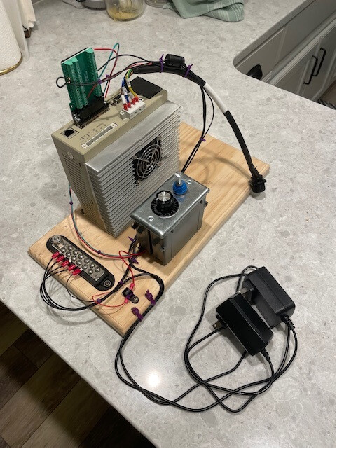
In case anyone is interested - I purchased 2 power adapters from amazon (One for 24VDC and another for 10VDC - that’s why you see 2 in the pic… The 24V supply was used to power the CN1 pin 31 while the 10VDC adapter was used to power the center pin on my 10Kohm POT. Its possible I could have used a level shift or something such that only 1 power adapter would have been necessary, but I am an electrical novice and simply used what I was comfortable with. the DB44 CN1 PCB was also purchased from Amazon and made the connections really easy. P046 in the drive is set to 400 such that 4,000RPM is achieved at full sweep of my 0-10v POT… Aside from this, I have not touched any other drive settings. I am assuming they are proper from Langmuir, but not 100% sure.
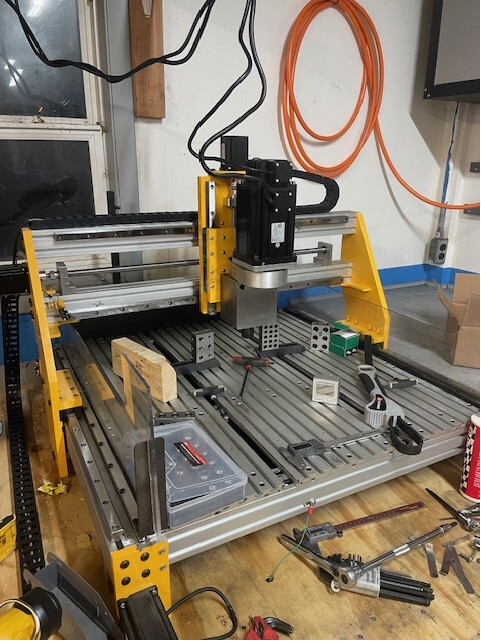
Up and running! This is my HEAVILY modified MillRight Power Route Plus machine… The Power Route is a great wood cutting machine, but I am trying to make it more suitable for aluminum and steel. Going to do some cutting later on in the week