Toolpath-Linking constraint, F360

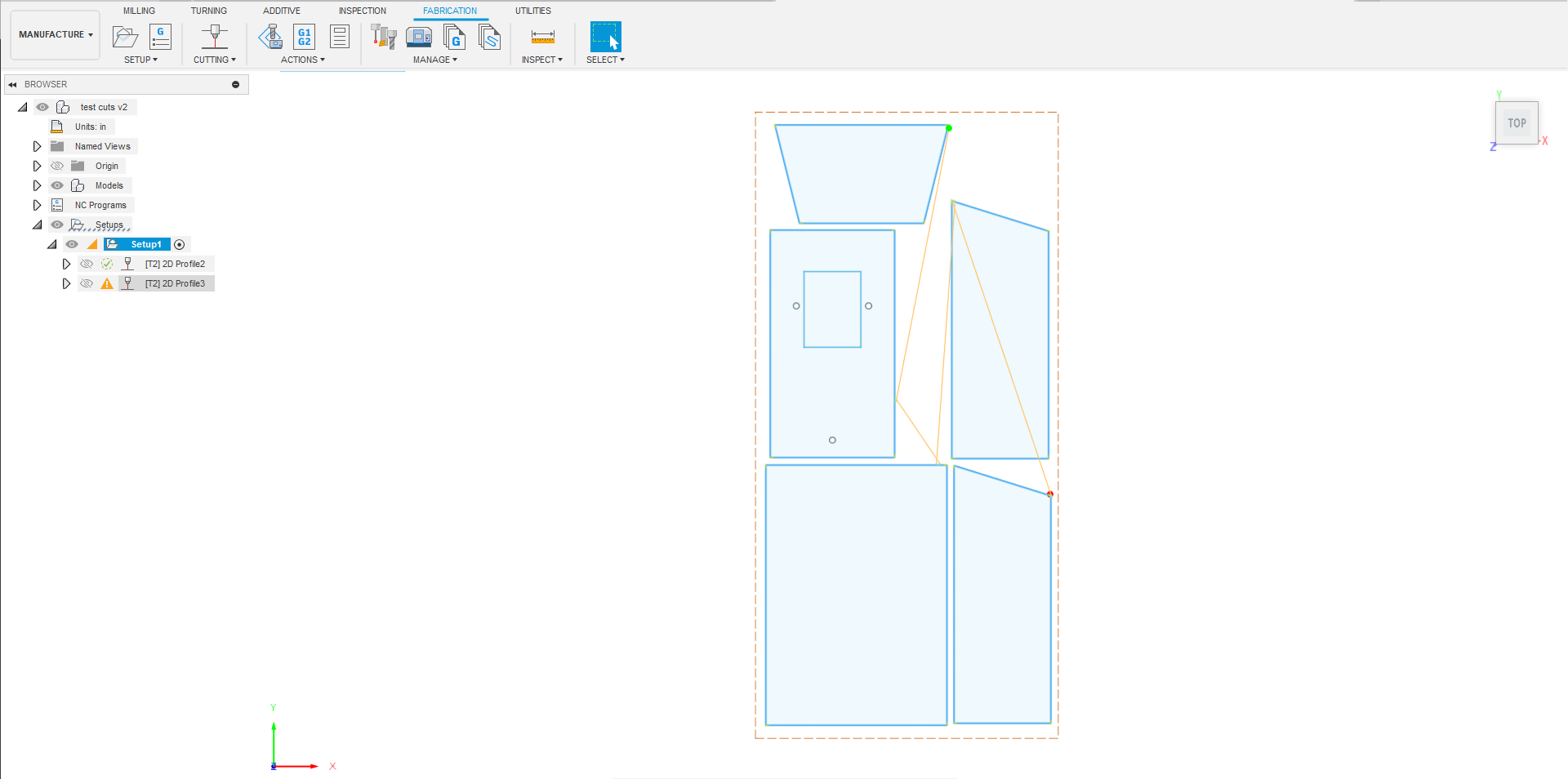
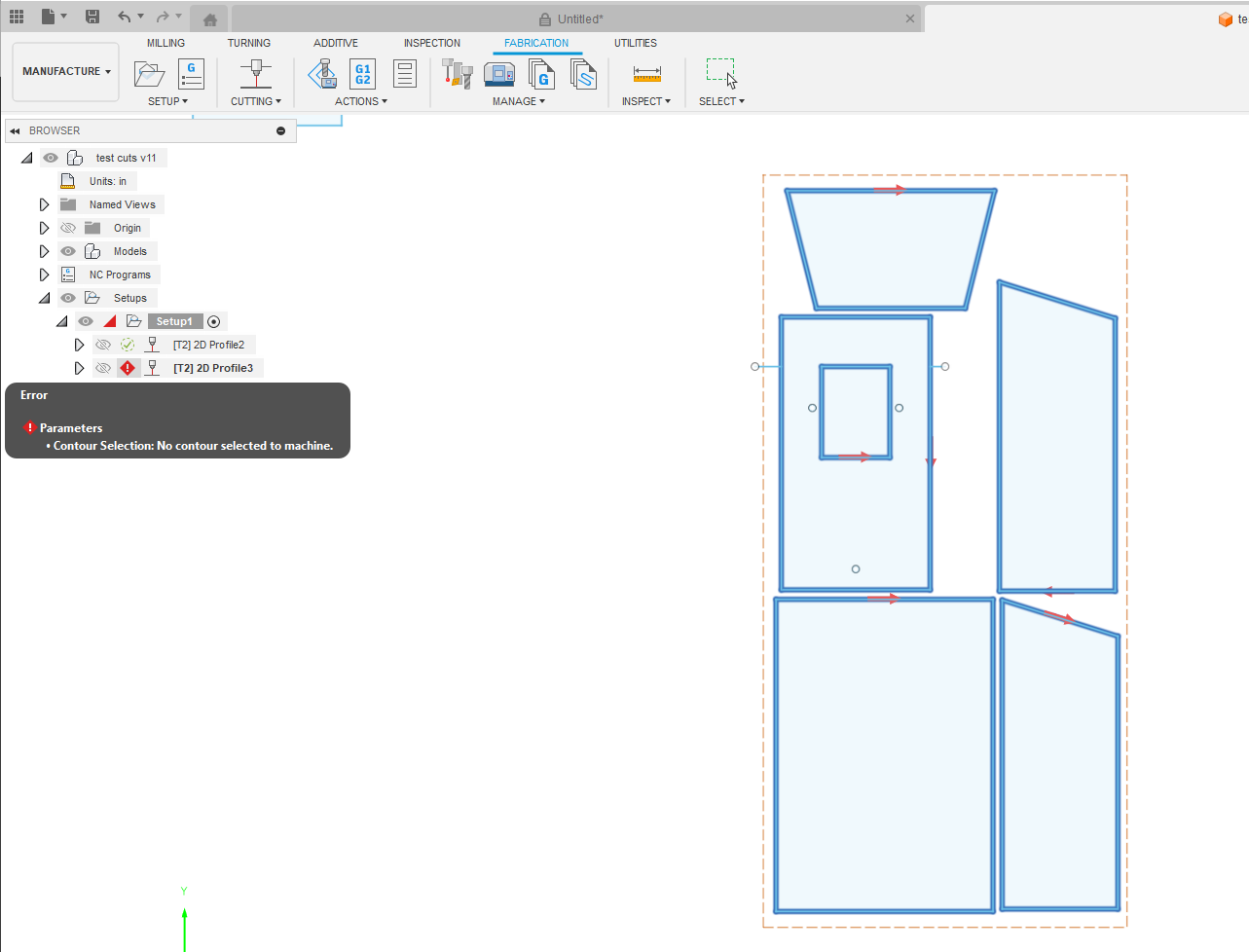
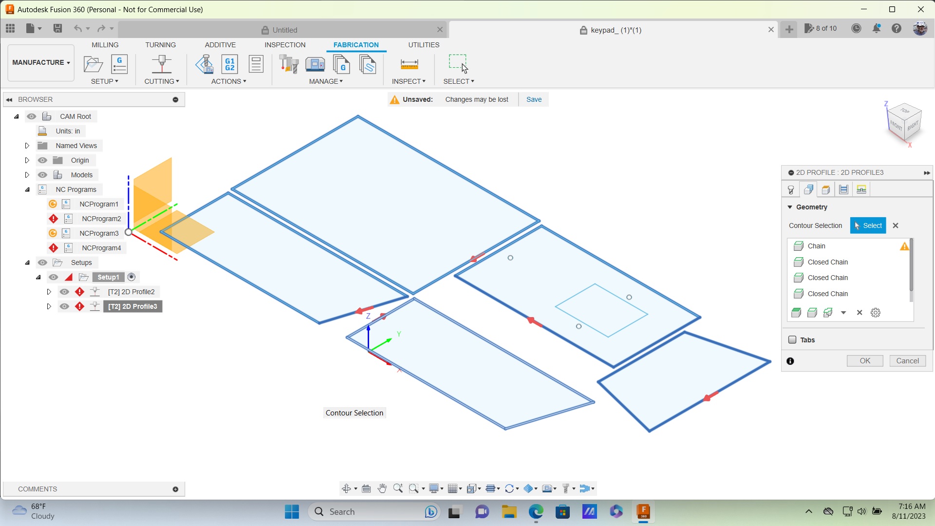
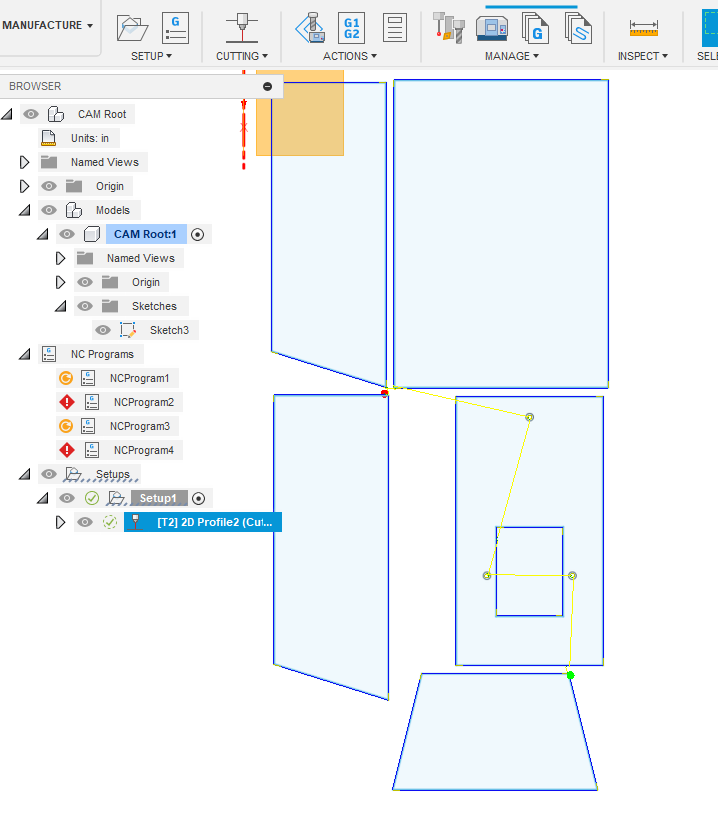
New to this, so patience please. Ran the simulation, project is not cutting the small rectangular shape inside the two small circles, but shows cutting direction (red arrows) when selecting. Everything else cuts fine. Profile 2 is for the holes only, Profile 3 is everything else.

Lead in/out-on, 0.1"
Sweep angle, 45
Feed Optimization-on, 0.2"

Thanks for the help!

Post your F3D and I can show you exactly what went wrong with your tools path.

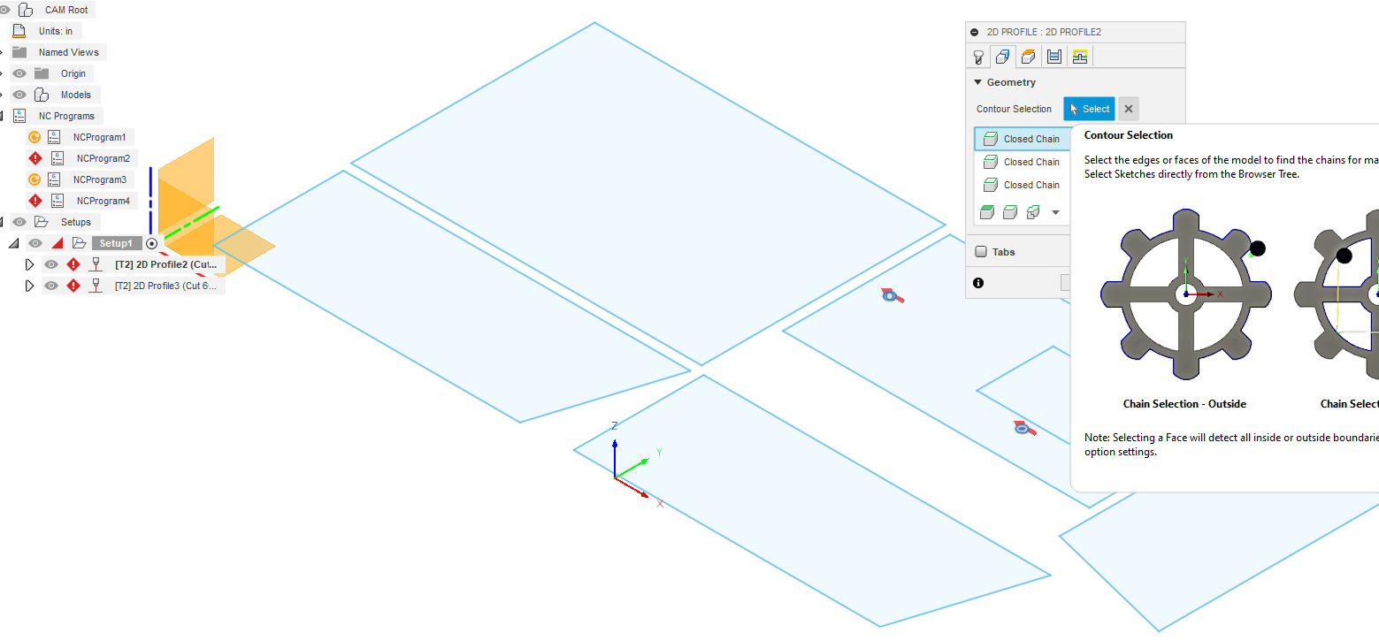
normally fusion “discards” any contours that the total of the “linking constraints” will not fit into. you can see on the left in the browser bar the yellow triangle with exclamation mark on profile alerting you to the paths being discarded

“linking constraints” are the lead in, lead out, pierce clearance, kerf width, etc all the option in the “linking” tab of the 2d profile menu .

1 Like

Just because I could, redrew the smaller rectangle and get this error now.

likely the manufacturing needed to be update to reflect the design changes.

try action> generate

This is how you can post an f3d

Made a few changes, and seems like I have really screwed it up. Here is the file.
keypad_.f3d (114.9 KB)

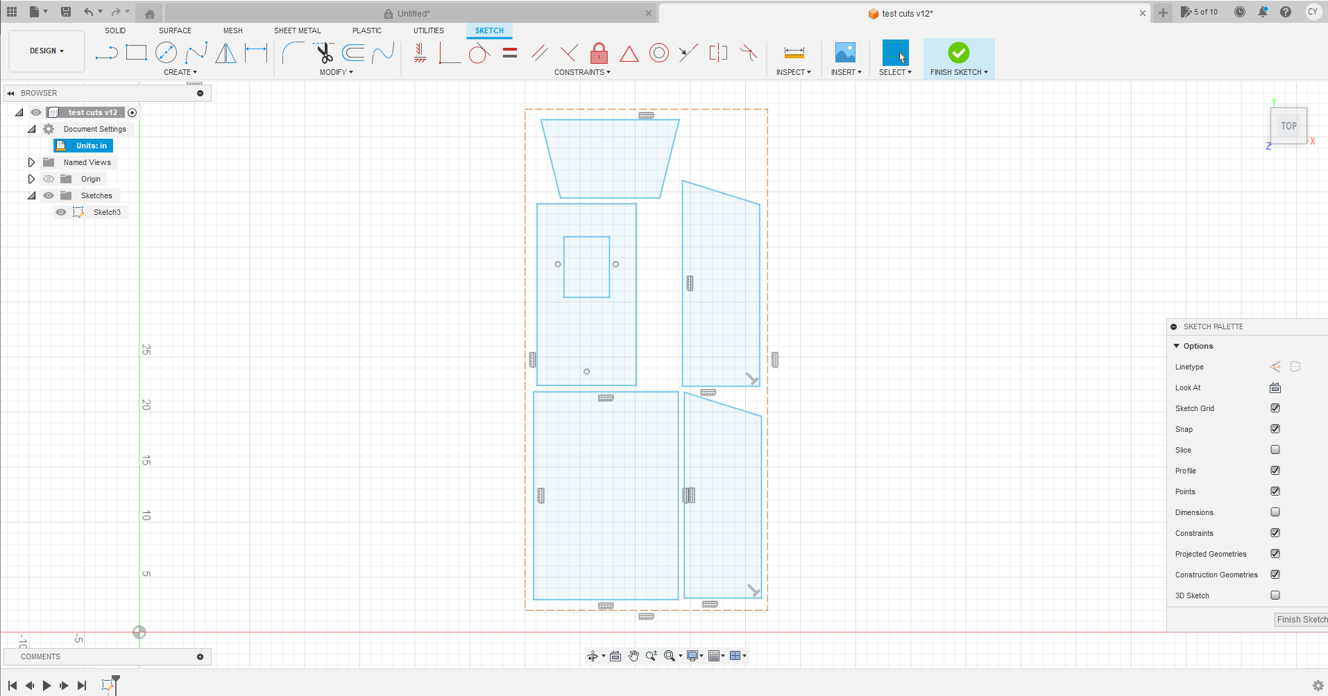
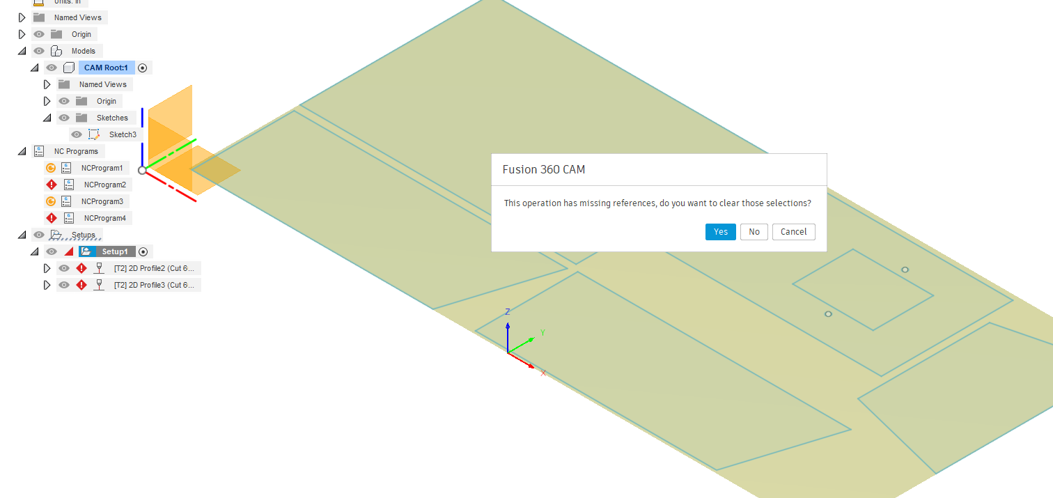
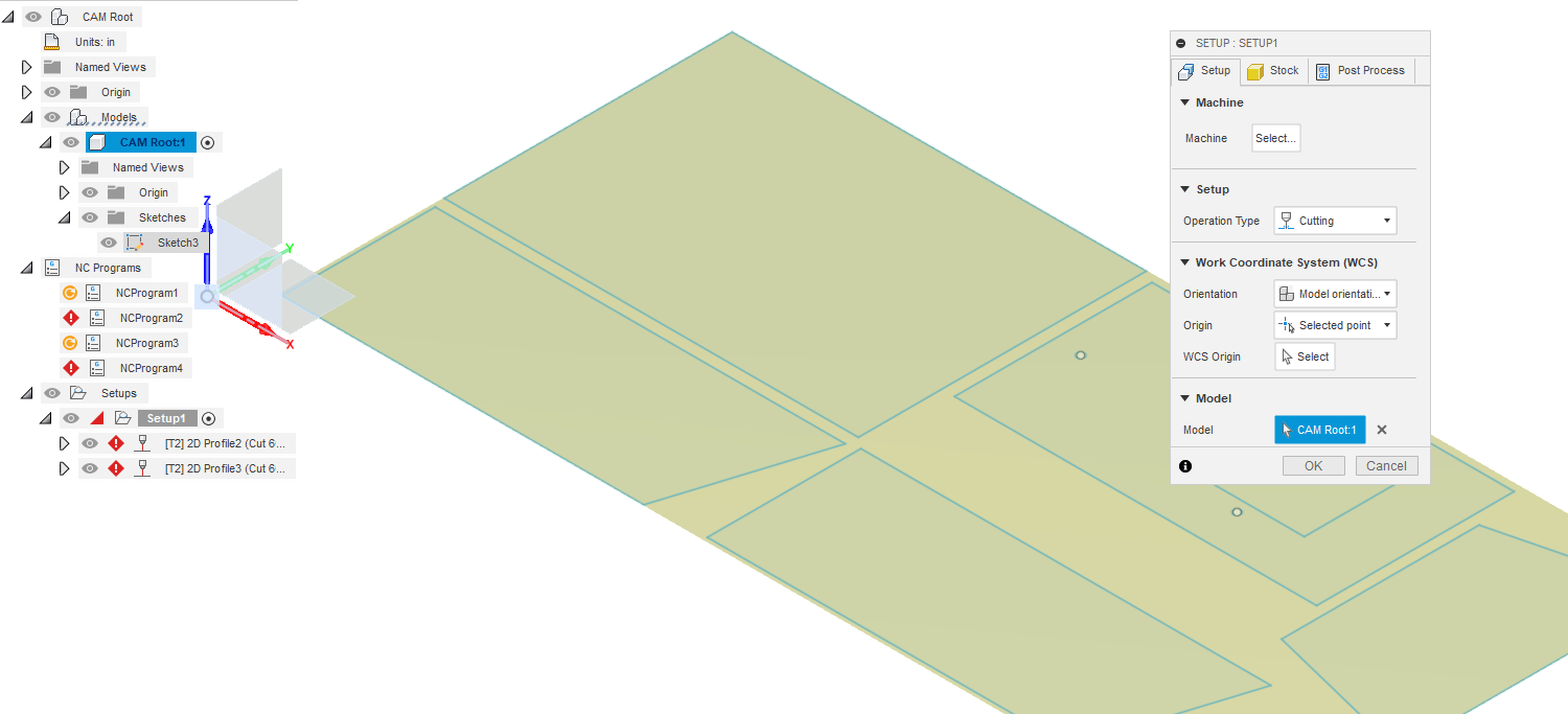
I took a look and It looks like you have two origins. I tried to delete your set ups and it wont let me for some reason.
I’m not that good with fusion, I would start a new drawing, if I was in a hurry.

I’m sure someone will fix it for you if you cant wait.

I opened it and it shows that rectangle is not selected. When I tried to edit your cutting program, it wouldn’t let me select that rectangle.

I deleted your Setup and create a new one, created a new cutting configuration and it shows everything cut in the simulation.

2 Likes

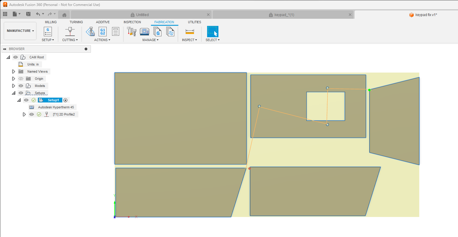
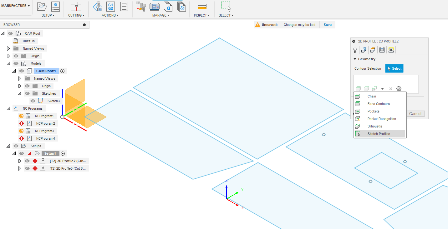
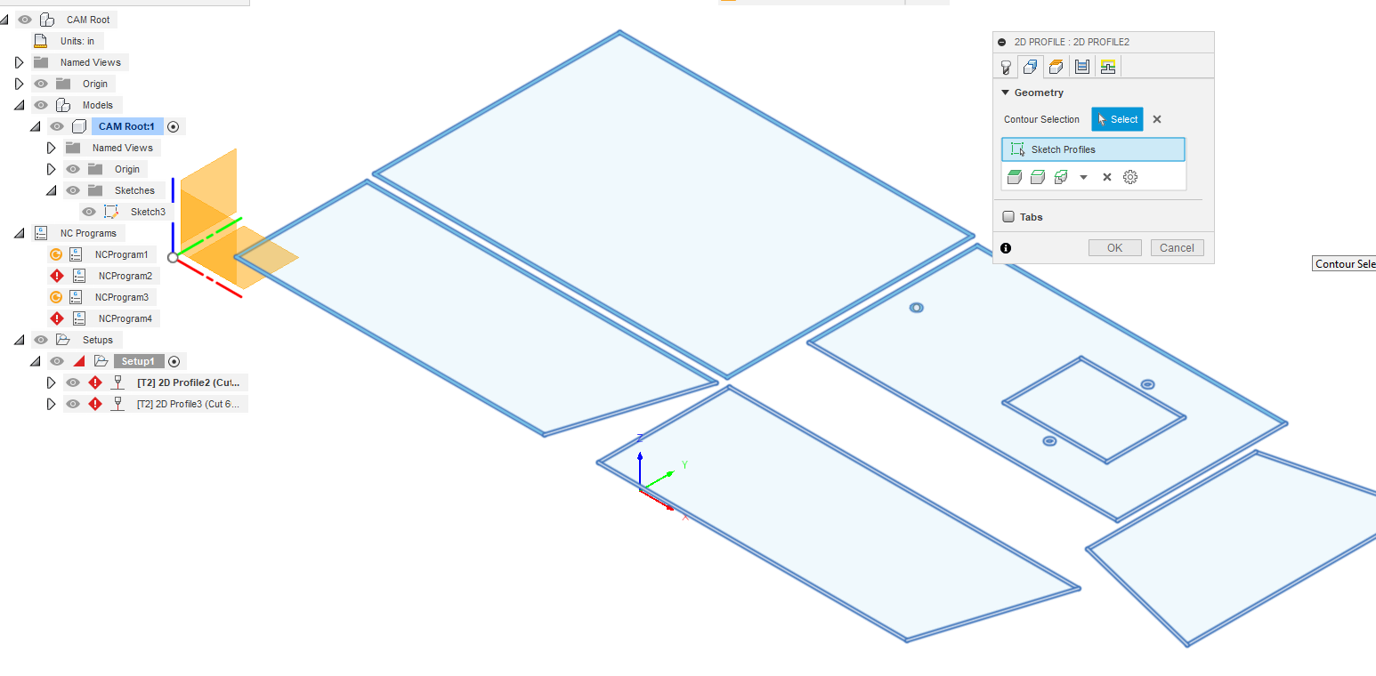
I created new f3d file for you so you can see how I would do the cut path. I have different plasma cutter and setup. I don’t select each line or hole. Let me know if you have more questions.

keypad fix v1.f3d (128.1 KB)

3 Likes

I cant thank you enough! Perfect. I ended up creating two profiles, 1 to cut the holes at different parameters, and 1 for all of the simple cuts. Modified, posted, everything seems ok. Cutting tomorrow…stay tuned.

1 Like

Np…it’s a fun hobby but takes a month or two to get things figured out.

1 Like

CAD is no problem for me…mechanical engineer, but I have never touched CAM…that is where the problem lies. Thanks again.

1 Like

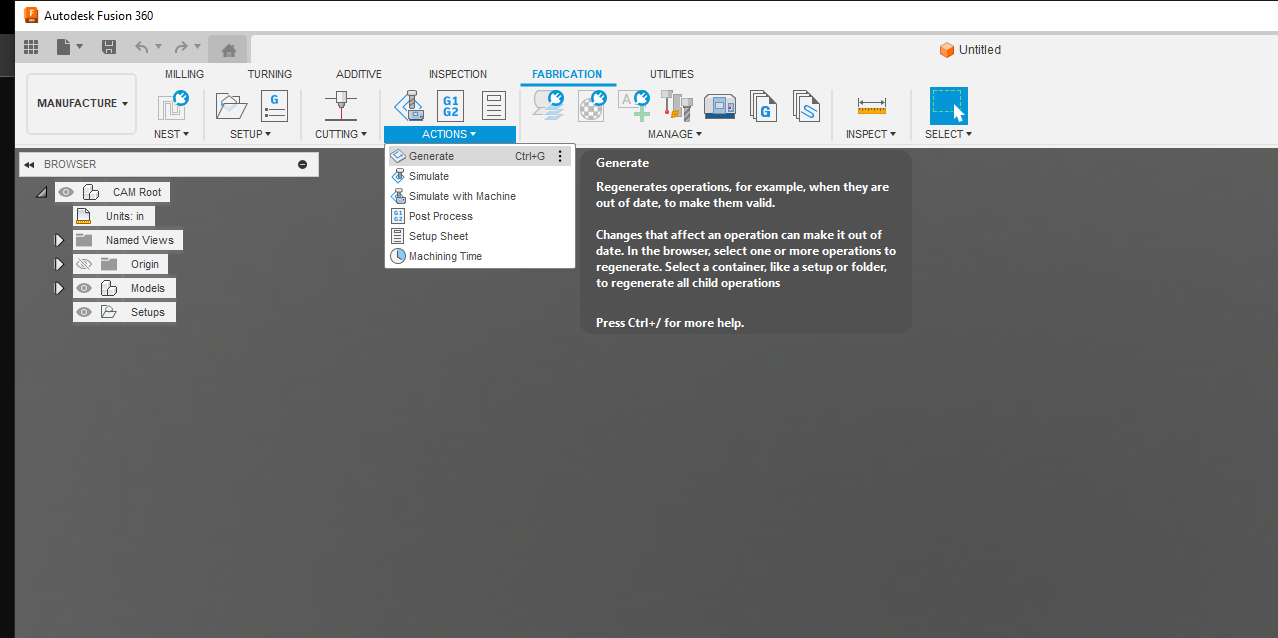
Just ran it. No problems. So just for my information, can you give me the exact steps you had to take to correct it? I am just trying to pinpoint my errors. Thanks again.

If you take a look and your file, you will find that in the Milling Set-up, there is an error with what body, contour or face was originally selected:


The dialog box asked if I wanted to clear that selection. I answered “Yes” and then proceeded to select the sketch as my “selection”

Here I cleared the selection in “setup” and selected the sketch in the file tree on the left:


Now the set-up is satisfied and I select OK for the set-up.

I now move to your contour selection. I could not see what you were selecting so I deleted all of your selections for contours:

I now pick the sketch for the contour selections, by first scrolling down to “sketch profiles”:

Now you find your sketch in the file tree on the left, (same as we did for the setup) and you see the contours are all picked up:

I deleted your second tool path as everything was picked up with the sketch profile

keypad_ChelanRevision.f3d (118.1 KB)

Toolpath was re-generated. It now has all green checkmarks next to the setup and the toolpath

In summary: your original set-up was not finding any object to use so the toolpaths were void to start with. If I were to guess, you were making changes to try to get the toolpaths to work out and in the process deleted some body or sketch elements. You will get it figured out…it takes time. Don’t despair.

4 Likes