So i watched the nyc cnc video along with this old tony and read several posts about it and im just not that kind of learner. The concept is escaping me on how to put a tool in and effectively program a thread operation. And I just cant afford to fail and learn over and over.
Im trying to make 5/8x24 threads internal and external. And im not sure if what im doing is correct not just from the tpi, which is basically no where to be found, but how deep the cut is into the part. To me its overly complicated for such a simple process with excessive data needing to be input on the tool and operation page.
I feel it should be as simple as select face and select threads no more info required (outside of normal milling speeds and feeds). Ive burned hours on slamming my head against the desk when it seems just using a good old tap and die would be quicker.
I use this guide that @AlexW posted. It is dead nuts on, or at least a start. My advice is to get a block of aluminum, drill a hole, and use the thread mill to dial in your settings. Start small and keep increasing till you get the correct fit. NYCNC has the best instructional video on thread milling.
I appreciate it ive seen that video and the pdf you supplied was like putting fuel on the fire. Its just more data that means next to nothing to me.
In nyc cnc he references thread pitch for 1/4-20 at 1:30 and says its 1/20 or .05. where in the hell did he get that equation? He doesn’t explain it youre just expected to know.
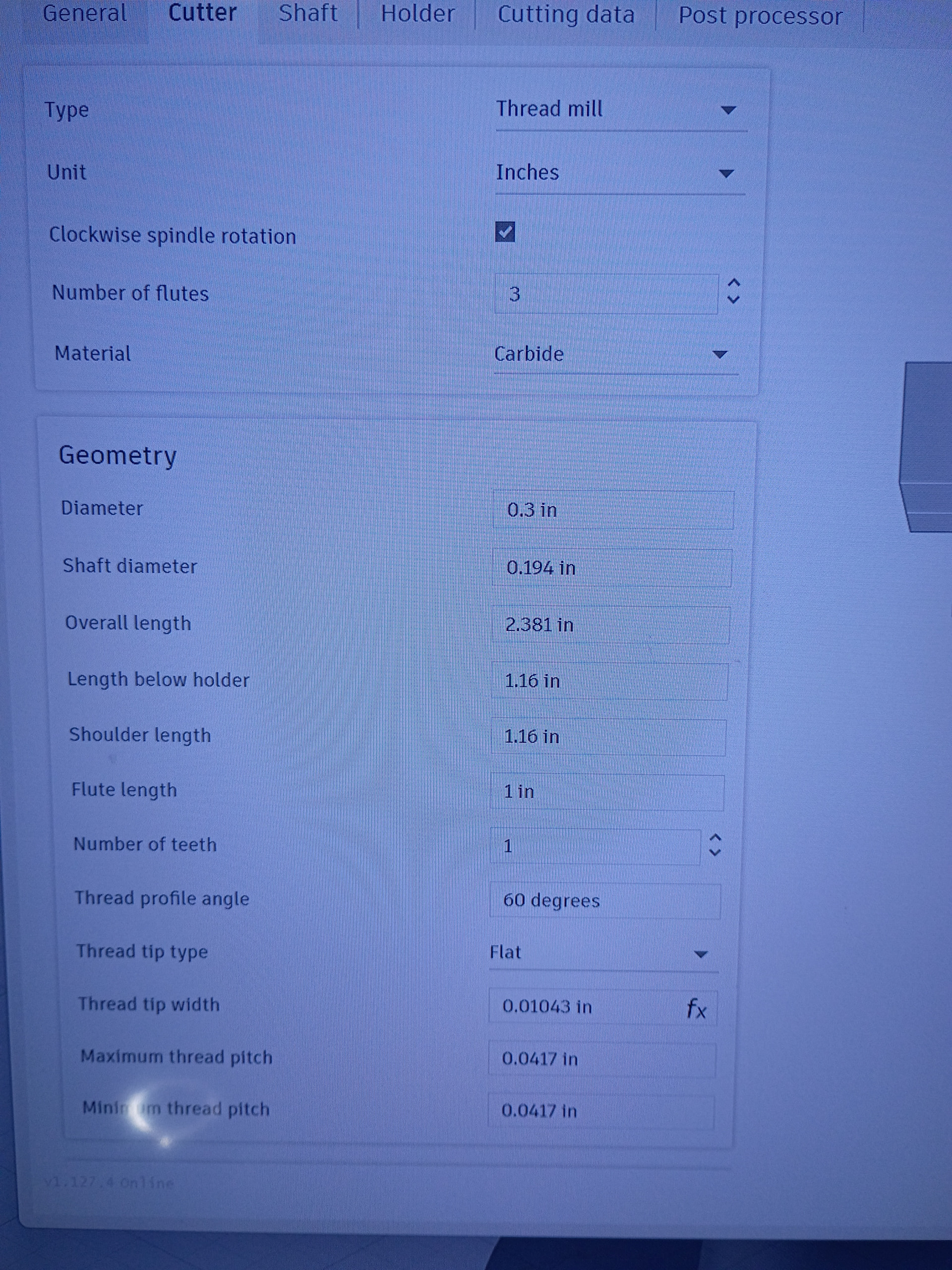
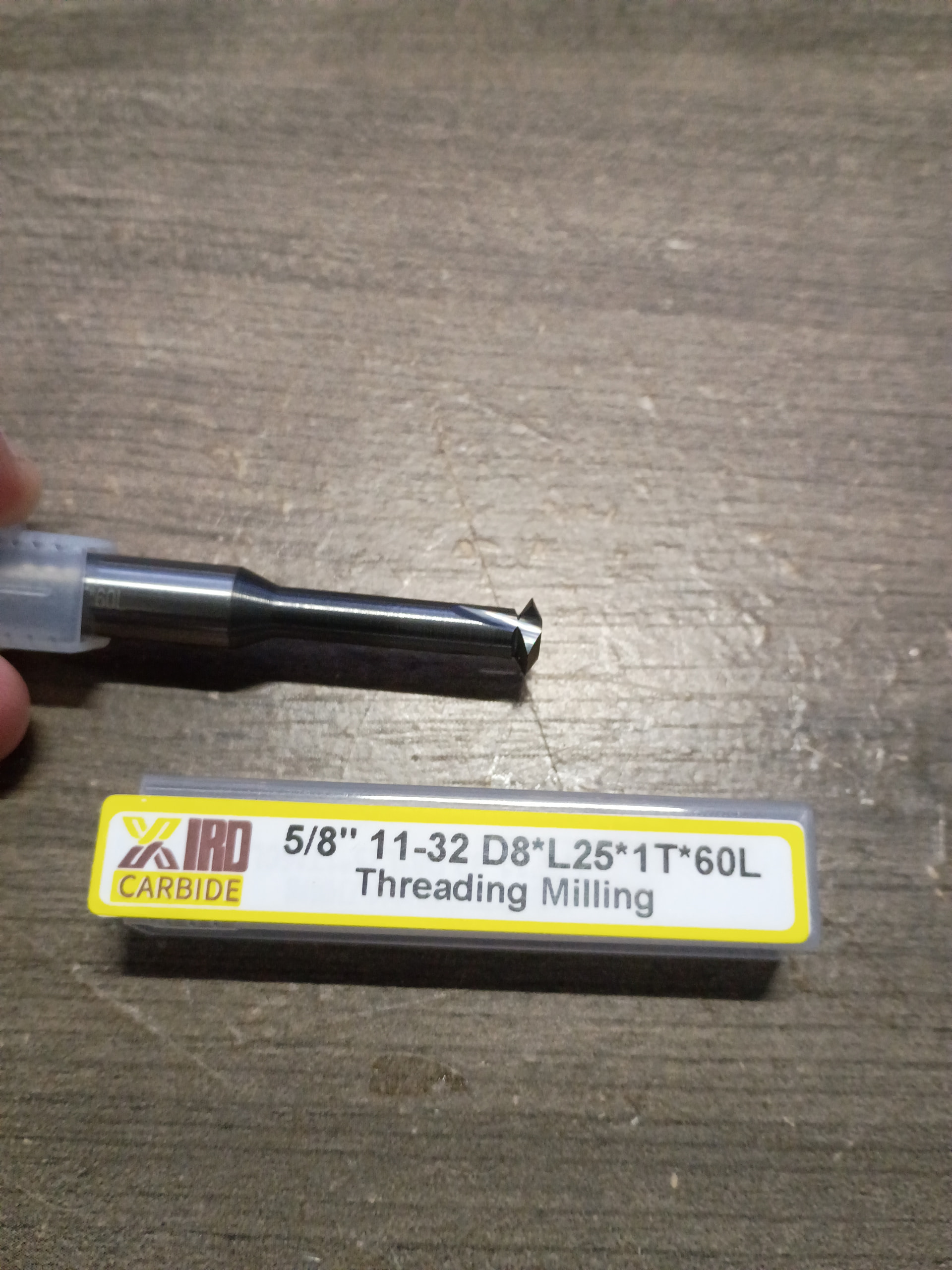
Another big issue is these tools dont have any legible info on them. The tool i have says 5/8 11-32. Ok great it does 5/8 threads from 11 to 33 tpi. But then theres a d8 l25 1t 60l that has no meaning. Theres no guides for it, whats the angle for the cutter? Whats the crest size? Whats the thread tip width? You need all this info for the tool library and it seems no tools have this info. Its all coded mumbo jumbo.
So nyc cnc is putting all this info in but you cant even get started to adjust and make threads.
Ok i dont know why they would do metric tool for imperial threads i bought it specifically for these threads.
Yes 5/8x24 is for muzzle brakes im in the firearms business, i have design experience its the machining that im branching off into because no one seems to want to make anything anymore so i get to do it myself now.
That mill is 150 bucks. I cannot afford to use that mill for learning, can the mill i bought do the job? otherwise im gonna return it and just by normal tap and dyes because ive burned to much time already on this.
I would not know how to import that data into Fusion for an imperial thread with metric dimensions. Maybe some of our milling guys could chime in. Sorry, but a tap at this point would be easier.
Thread pitch is always 1 divided by the number of threads per inch for imperial units. 1/4-20 is 1 divided by 20 or .05, 5/8-24 would be 1 divided by 24 or .041667. That’s the number Fusion wants input. I suspect that since your tool has metric dimensions D8 means the tool cutting diameter is 8mm or .315 inches, L is cutting depth 25.1mm or .9882 and T is over all length 60 mm or 2.362. Check these measurements with your calipers and input them in your tool library .
Thanks for explaining that, when a thread mill has a range of TPI, like this one going from 11 to 32 do i but .0909 and .0312 in the max and min thread pitch in the tool library cutter tab? And then on the actual threading operation i put .0416 on the thread pitch box and that will determine what thread gets cut with that tool?
I will need to make up just a general file with the threads and tool info, i dont post or share my raw work online. I appreciate the help but when youre trying to make a living people will just grab your work.
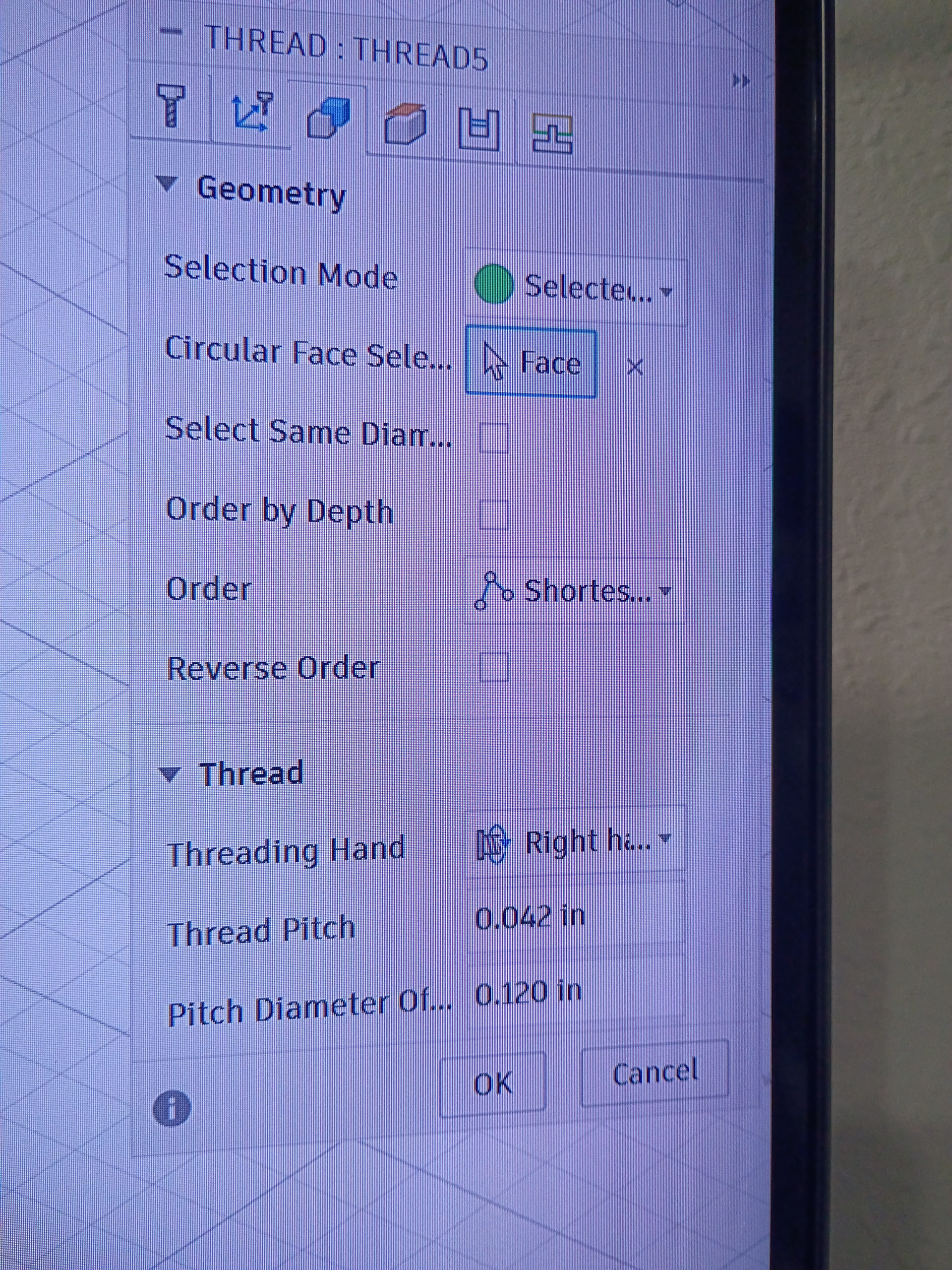
Don’t forget input the pitch diameter offset in the geometry tab. You can use the NYCNC excel spreadsheet to calculate it. The offset is dependent on your CAD model. If you drew the model with 5/8 (.0625) holes the offset will be different that if you drew the model with 19/32 (.594) holes ( this is the hole size for a 5/8-24 tap). To get the crest size you will need a magnifying glass to observe the very edge of the point of the cutter to measure the flat on the end. It may look like the cutter comes to a sharp point to the naked eye but it has a flat on the end somewhere between .003 and .001. You need this information to correctly calculate the offset.
Awesome thank you, 1 last question. Pitch diameter offset is what i need to dial in correct? Should i take major diameter and subtract pitch diameter for .0271 and punch that in first or should i start shallower and work my way up.
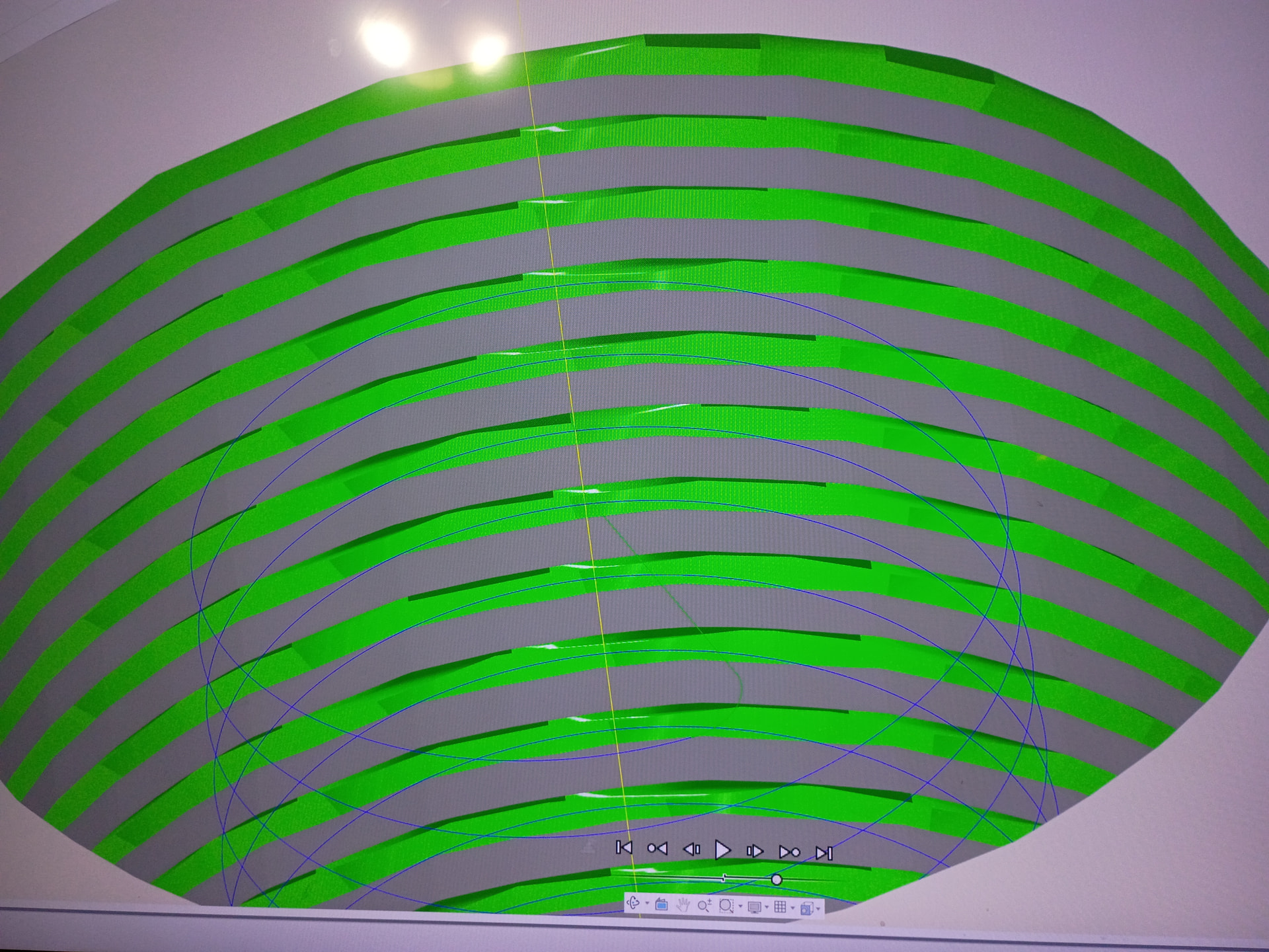
When i simulate the operation the threads look flat but it could just be the simulation and me not knowing what it should look like.
The pitch diameter offset can be dialed in , if you start with a crest size of .003 the offset for a .625 modeled hole is .005. As the crest gets smaller the offset get larger. What size is the hole in your CAD drawing?
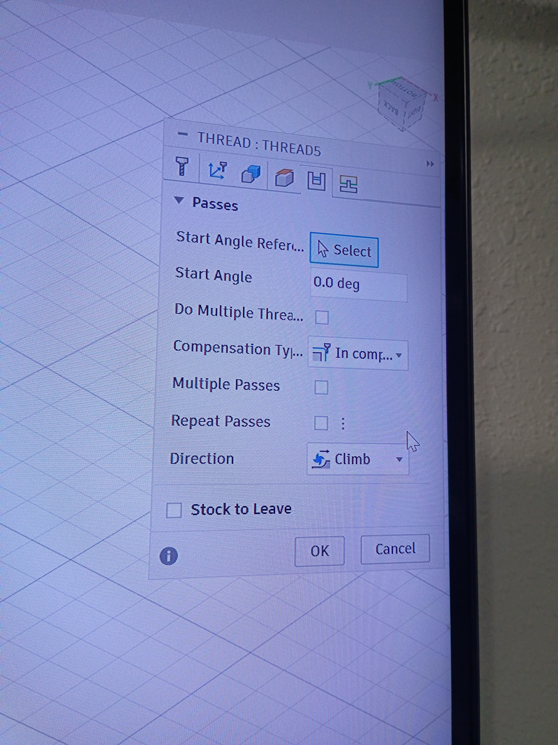
Don’t try to cut the thread in one pass. That creates too much tool pressure. Use multiple passes 3 to 4 with a .010 step over. Yes this will take longer than a single pass but will keep the tool from breaking.
The hole is .625 but i think now that you mention it i screwed that up, it should be thr minor diameter of .575 correct?
I redid the op for multiple passes at a .027 pitch offset, the first 2 passes dont cut anything with a revised hole diameter of .575 the last 2 do all the work.
Why not just model the thread in fusion design view to whatever you need, then use the (new) feature just released that auto calcs the thread mill in the manufacture tab? You just select the hole and it’ll automatically detect what thread you designed
Where do i find that feature? I did do a modeled thread but i got rid of it because it was overlapping my simulation cut and was hard to see as it wasnt lined up.
So im trying to use formed threads from the design by selecting the groove crest and running the op and im just getting this ghost layer. Its like the TPI is off but im using .042 for the pitch. With a .024 pitch diameter. Assigning the thread function to the groove crest should make it follow the threading like a normal mill OP but it isnt. Also it doesnt appear that the thread grows more offset as the thread is formed down the shaft.
Editted to add
I believe the start angle was off. For some reason the op didnt follow the design thread it started wherever it wanted. I was able to rotate the start angle 225 degrees and line up the threads.