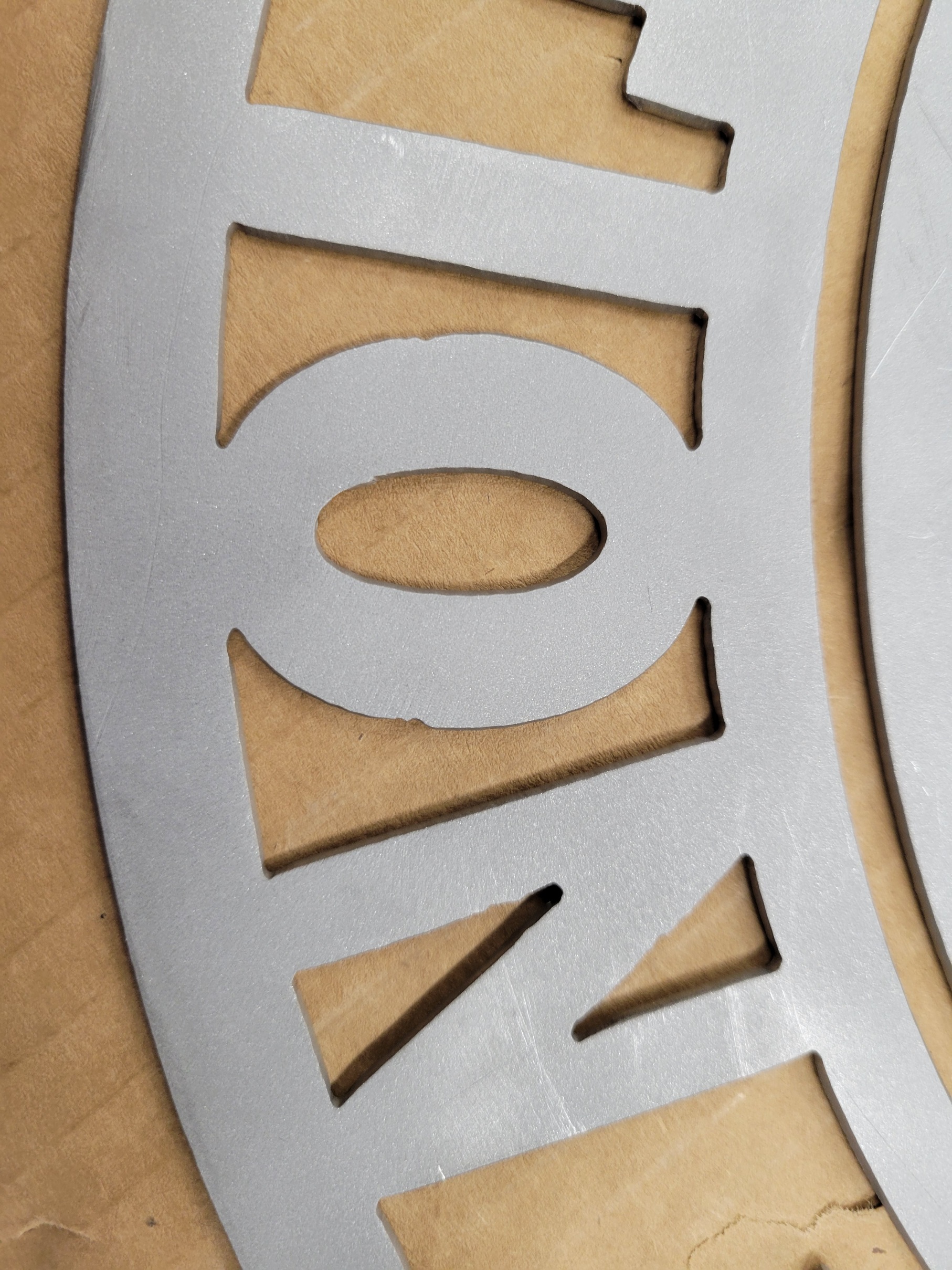
Still trying to fine tune… getting pierce marks still. Down to a 25 degree lead in radius. .025 lead in distance, kerf set at .047, pierce at .6 seconds, 220ipm at 45amps on hypertherm 45xp with fine consumables… any help appreciated…
The lead-in is too short. Anything less than the size of the kerf will result in some divot. Usually I start with about 2X the kerf so it’s backed away far enough from the cutline that it shouldn’t impinge on the cutline. The lead-in divot tends to be larger than the kerf because the head is sitting while establishing the arc so you tend to get more burning than when the arc is established and the head is moving.
6 Likes
On top of what was said, if your actual kerf is >0.047, then 0.025 won’t clear it fully. I’d suggest running some line tests to dial-in your pierce delay and kerf width….
2 Likes
So i am now at .125 lead in, and i still get pierce marks… this is getting extremely frusterating to say the least.
There’s no way you are running a lead in/lead out of 1/8” and getting pierce marks - unless the area is too small for a lead in / out. In Sheetcam, you can set the lead in / out length, but still have to choose a type, or the value is ignored and no lead in/out is used. Guessing you haven’t chosen what type. If you’re using Fusion, I can’t help you there.
Do you mind posting your *.f3d file.
I’ll be able to directly compare what you got going on for a parameters versus what I typically use.
Everything is tight as far as all your axis z x y .I remember you’re having an issue with chatter that was related to slop previously.
25° lead in is going to end up giving you a hotter spot than doing a 60° or more. The only reason I typically go for more of an acute leading angle is to fit in tight geometry
YELLOWSTONE FINAL v2.f3d (801.8 KB)
TinWhisperer will get you fixed up with respect to the lead in/out type and length. I don’t know if its possible in Fusion but, in Sheetcam, I would move those pierce locations to a curve or corner where they would be less noticeable than in the middle of a straight line.
2 Likes
yeah, i cant for the life of me figure out how to do that in Fusion 360… I bought the sheetcam license and might start going that route. But just trying to figure out one software and get the kinks ironed out first. Lots to learn
I answered that question about entry positions on one of your previous topics.
I’m out in the field for a few hours as soon as I get back to the shop I can fire up your file and see where you’re at.
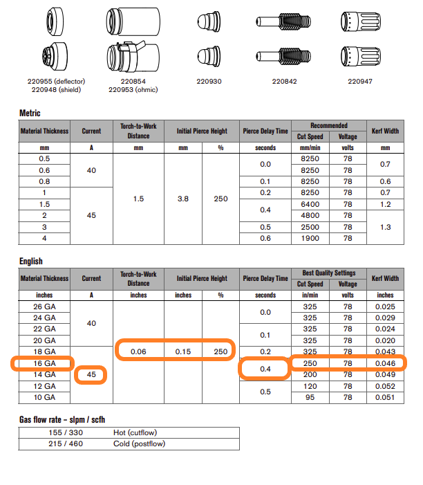
Is it 14 gauge mild steel?
Everything’s possible with fusion. lol
I’ve been thinking about buying a sheet cam license just to play around with it.
I can’t see where I’d fit it into my current workflow though. I’d probably just learn it to help other people troubleshoot it.
Sheet cam does have a couple tools as far as I know on fusion but fusion 360 is updating at a very steady pace. I’m really hoping they’re going to add a true hole lead in similar to what hypertherm’s cad cam does.maybe in the future.
No doubt there is. I still find myself doing fusion tutorial videos a couple three times a week. I also spend quite a bit of time on the fusion 360 forum site.
There is a endless amount of stuff to learn and tips and tricks.
16 gauge steel
The “start at center of holes” feature is really nice in Sheetcam. It starts at the center of all holes under a user specified size and spirals out to cut a really clean round hole.
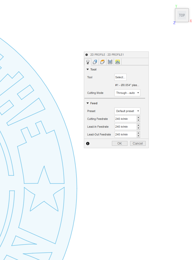
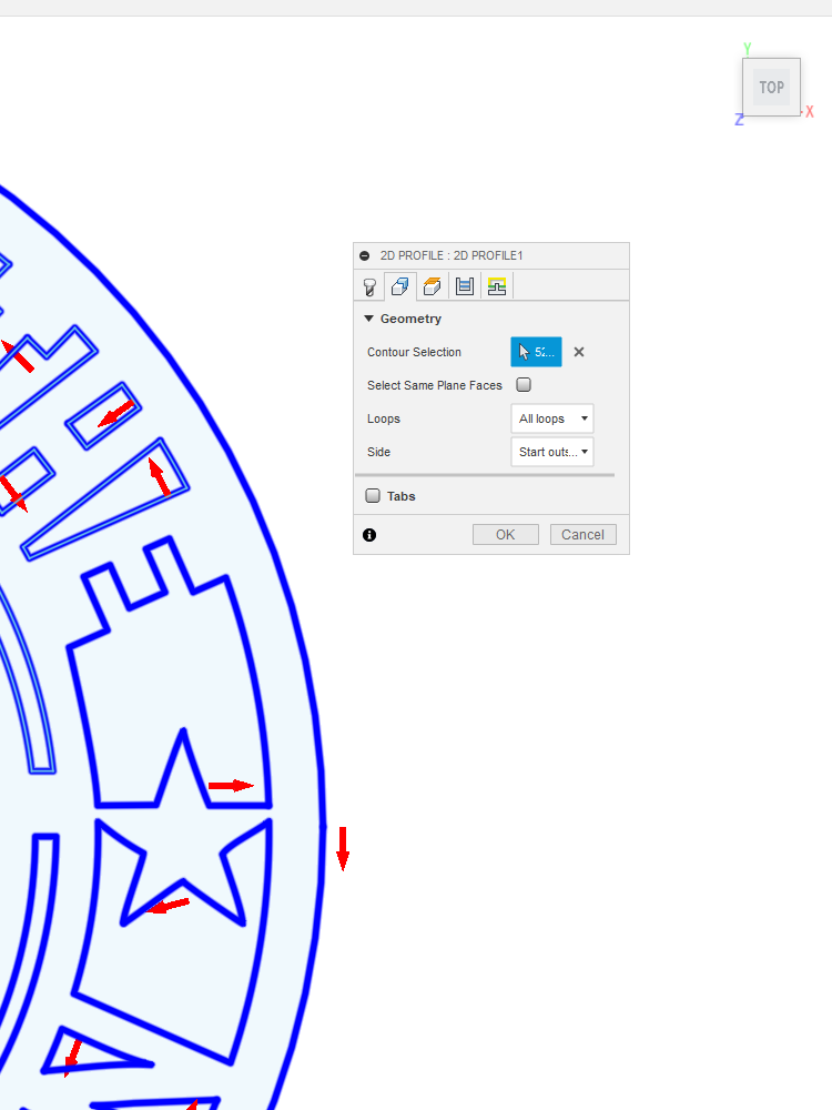
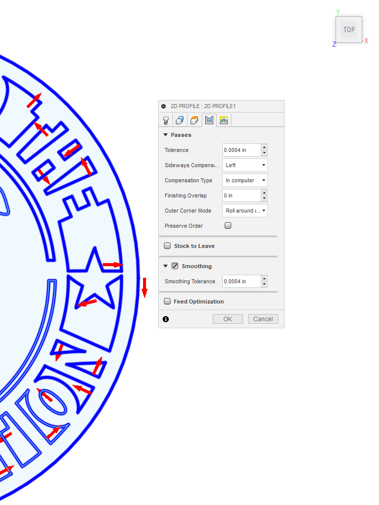
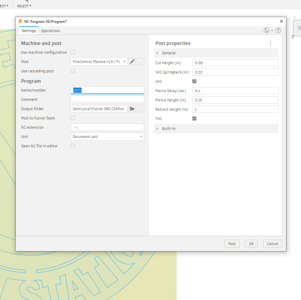
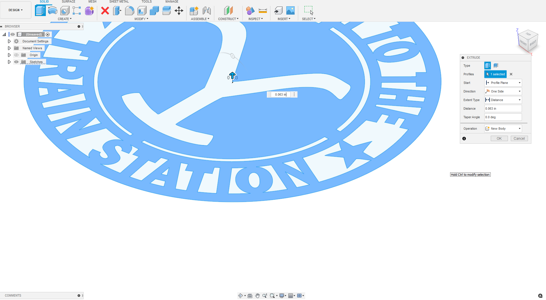
Here are your current parameters:
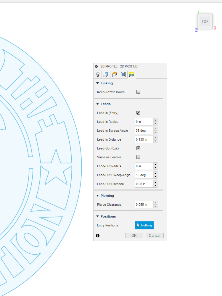
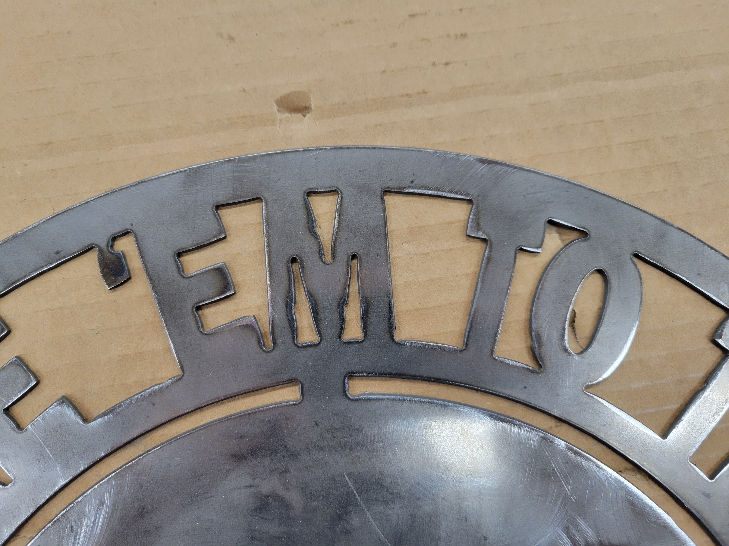
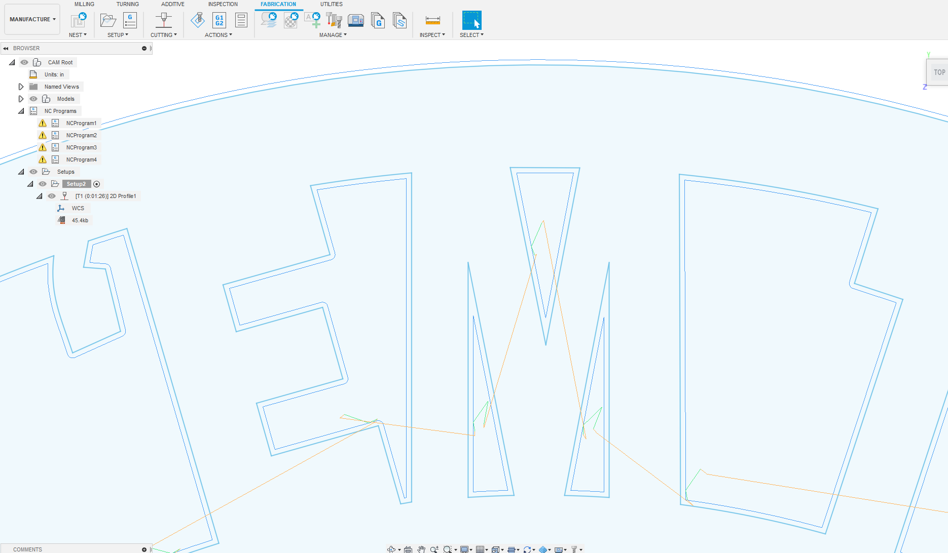
here is the lead in and out on fusion360 compare to your picture.
The M has the most noticeable flaws.
These are you current torch parameters .
I see you have a kerf of .054" and a ipm of 240 in the programs above.
I’ll run some new setting and post something shortly .
Yeah I have tried kerf at reccommended all the way up to .07 to play with what it does. Pierce delay as short as .2 to .8 seconds. Adjusted lead in this morning on two pieces I cut to get rid of those double length lead in on the m’s and adjusted to 60 degrees, as well as .004 on tolerance to try loser.
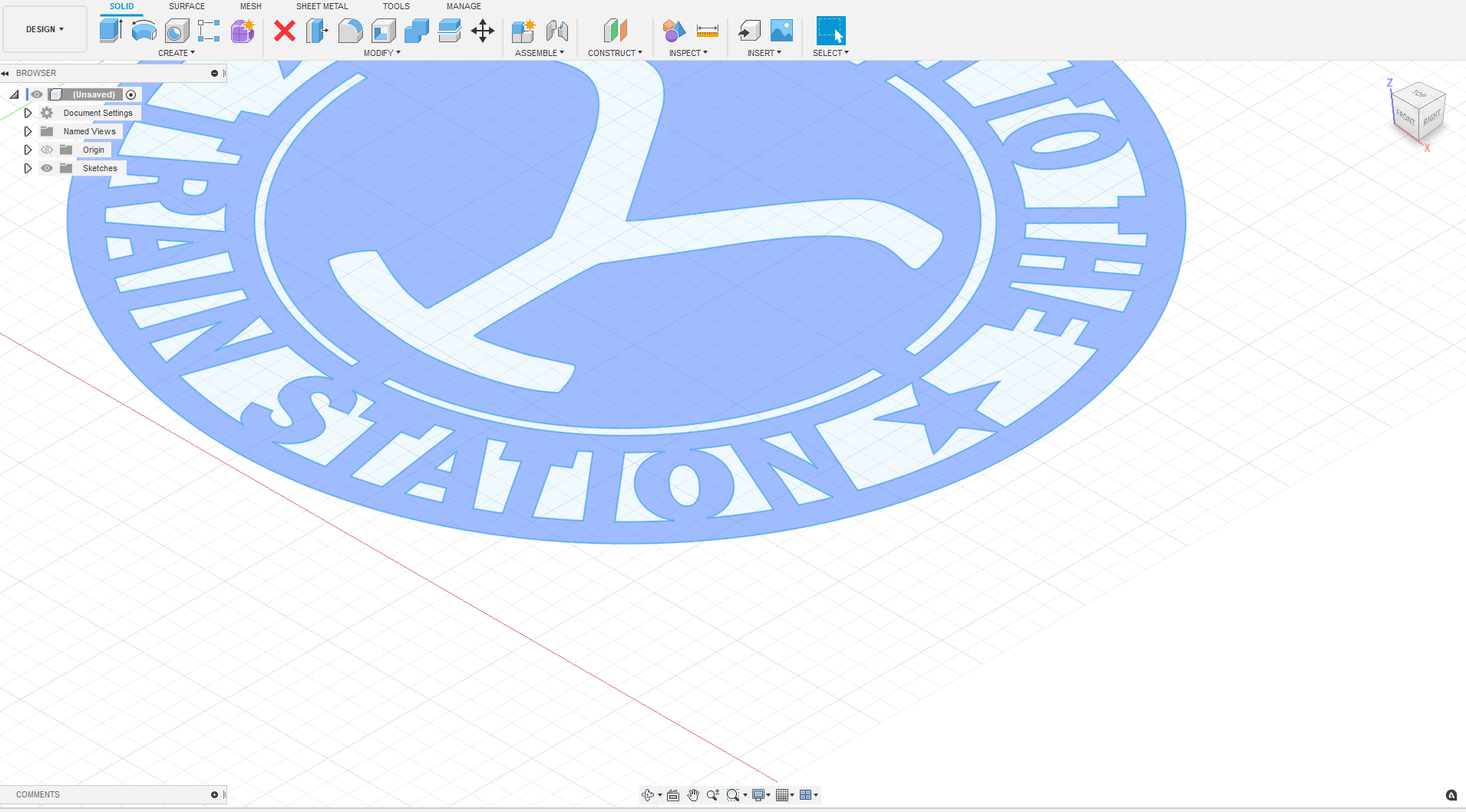
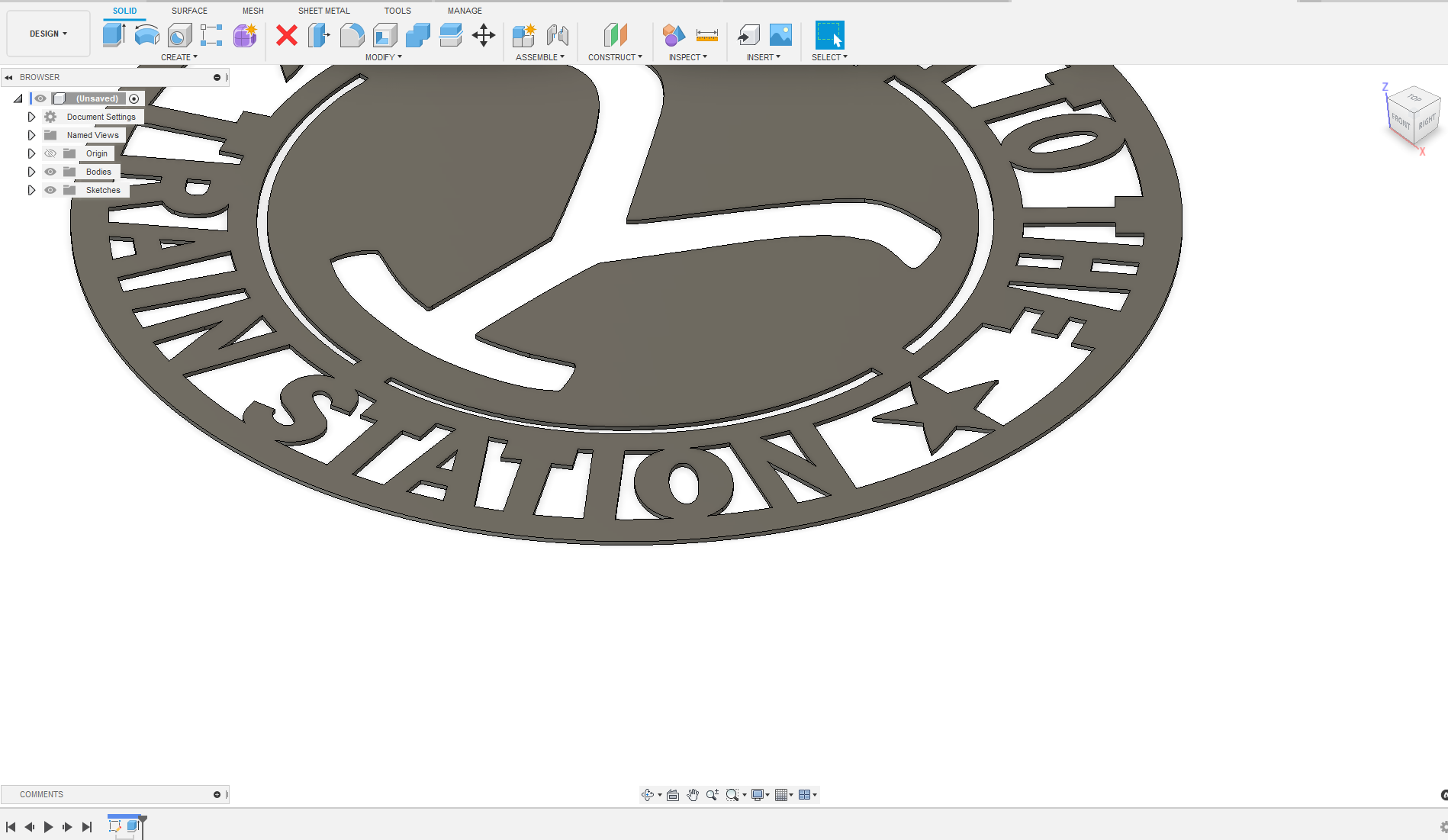
Life is made far easier by extruding.
They maybe times where you need to turn on the sketch as well like for single line cutting.
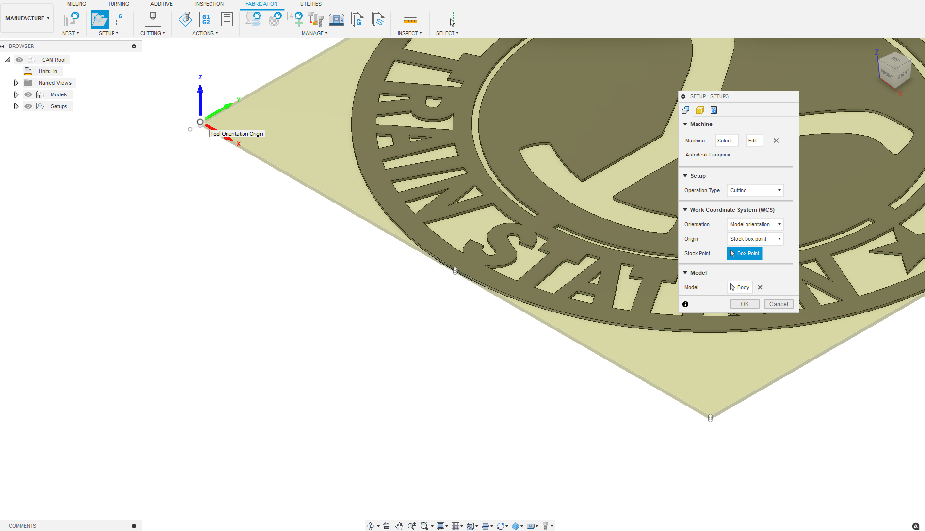
relocate your box point origin
I changed quite a few settings.
It is a very small piece at 16"
here is a F3D file with my mods and a cut file .
Train Station tin v2.f3d (1.6 MB)
Tstation.nc (39.8 KB)
add fresh consumables and air dry to this file and your results should improve some.
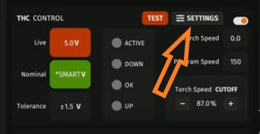
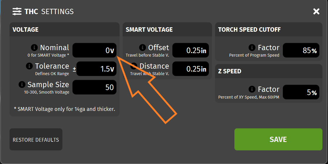
Ground clamp on material and write in your nominal voltage in the THC 78 volts.
you could also do this in 2 operations and have longer lead in and out for the larger openings.
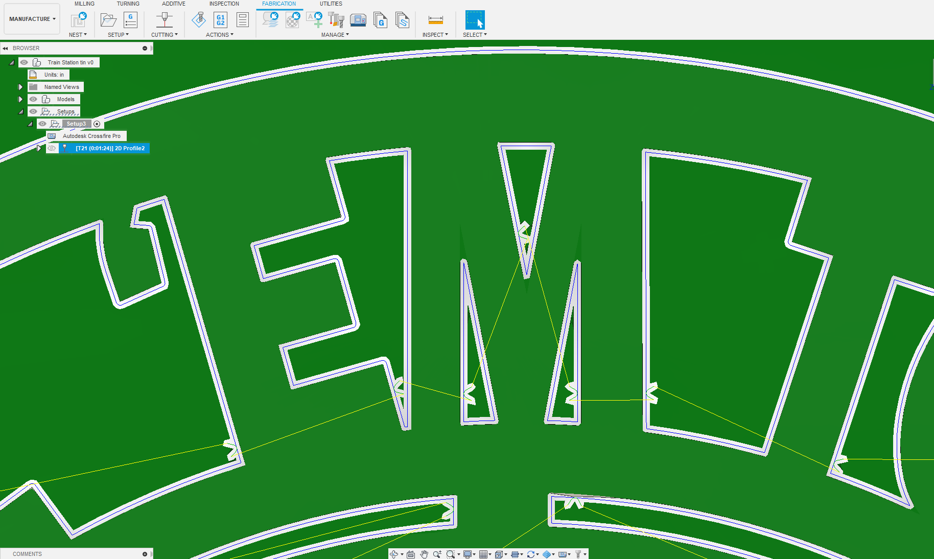
In the file i relocated I bunch on the lead ins in the tight corners
1 Like
how do you write in 78 volts on THC?