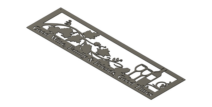
Good morning folks, i am attempting to get a file i found on file share to a cut ready state. Good Wine... Wall Art | FireShare | Langmuir Systems
i am using fusion exclusively for design and tool path generation. when i open the dxf file in fusion and begin to create a tool path the inner single line geometry like the grape clusters are a combination of a ton of very short line segments. in order to select all of that inner geometry is it really necessary to click on each tiny line segment or am i missing some much easier method of creating tool paths along those segmented lines? should i be converting the dxf file in some manner that makes fusion recognize all those small segments as contiguous lines? thanks in advance for any suggestions. if you have time @TinWhisperer i welcome any suggestions you might have.
dylan
Yes try double clicking when selecting
No, try double clicking when selecting.
check out this topic
also check out this video
good luck let me know if that works for you.
Now that I am looking at it more I think I may have found a faster way.
Down the rabbit hole.
If it works it will save me a ton of time in the future work flows.
Ill start a topic when I get this work flow figured out. Thanks for the question we maybe on to something new…
thank you for the suggestions. i haven’t tried them yet but starting now. i will let you know how it goes, and i look forward to hearing about your current epiphany!
@DnKFab the best thing you can do is create a rabbit hole for @TinWhisperer to explore. Firstly, he’ll come up with something very interesting, secondly, he’ll be diverted from his nefarious role as Manual Man! Something we’ll all welcome.
PS: Don’t tell him I told you this! ![]()
I am afraid @TinWhisperer has already been able to view… @TomWS . you forgot to use the invisible text setting on that last post! lol
Dang! I keep forgetting to do that! I think I’ve been cursed!
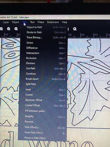
@TinWhisperer i want to run something by you…while awaiting your work around i might have stumbled onto something great!! lol. i was browsing google regarding my above mentioned issue…i ran across a tool utilized in inkscape called stroke to path…it is sorta explained on the linked page.
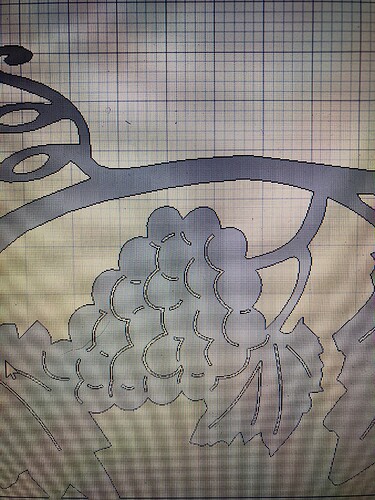
i opened the svg in inkscape…i selected the entire drawing and somehow i believe inkscape selected the individual single line paths…(strokes i am assuming) i selected stroke to path then i then chose to save as DXF r12…initially i tried saving as r14 but fusion did not like that version…the r12 version loaded into fusion…a bit slowly but that is probably my computer limitation…i then selected the face and extruded…all those solitary line segments had been changed into potenially cuttable paths it looks like…i am about to begin actually creating a tool path for it but it is looking positive so far. the only down side for me up to this point is it seems to really bog down fusion but if it doesnt crash then i will have saved myself a ton of time and aggravation. update to follow as i work my way through the tool path generation. the first photo is where in the menu that inkscape option is and the second photo is a pic of the extruded svg after the inkscape conversion
He’s reading the software manual right now,
But @DnKFab has the answer (stroke to path in Inkscape with an export as a R12 DXF).
Odd point of possible interest - I’ve never gotten anything later than R12 to work for DXF exports to be imported to F360. I’m not sure what the breaking change was in the standard or why it doesn’t work but since R12 is just as easy, it never rose to enough importance to try to determine the root cause.
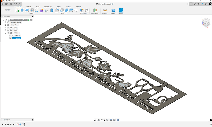
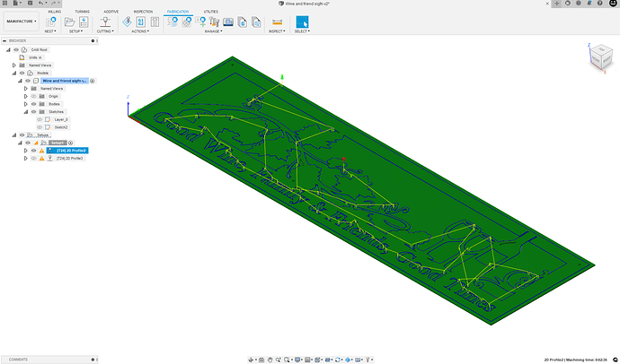
This is where I am so far.
-It maintains the single line geometry of the original piece
-All the single line geometry can select at once.
Started by inserting the DXF on XY
Then Extrude it. (E in the hotkey)
Toggle off the Visibility of the Body and First Sketch
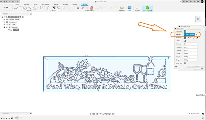
Now start a new sketch on XY and insert the Same DXF
Now Modify that sketch by erasing all non single Line Geometry.
Finish the 2nd Sketch
Toggle ON the visiblity for the bodes and 2nd Sketch
In the manufacture space create a new setup
Make the First toolpath and generate toolpath for the body.
Start a new toolpath ( aka New Operation )
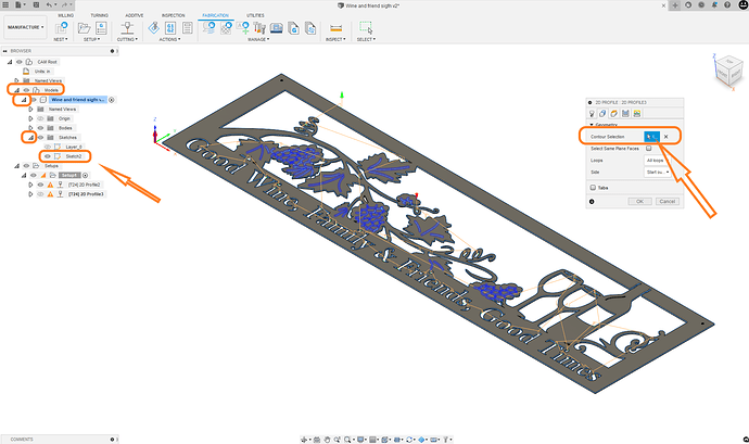
Select Contour Selection (right side of screen)
Under model Select Sketch 2, This will select all the lines (left side of screen)
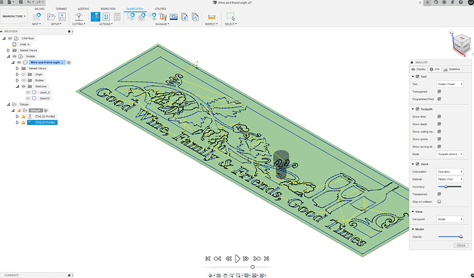
Generation 2nd toolpath (use centerline cut with ,no lead in and out and no pierce clearance )
That is it we are ready to make G code.
I see that being a very useful technique in some designs.
It does alter the geometry of the original Piece losing the single a effect and increase the cut time by over double for those areas.
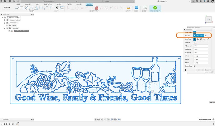
this DXF is really “heavy” 20419 pieces of sketch geometry.
I ve been having a memory issue with my PC lately and that DXF was bogging me down too.
Save often .
Let us know how the works
Here is a Reduced Sketch geometry version of the good wine DXF
down to 5062 pieces of sketch geometry.
reduced good wine DXF.dxf (740.2 KB)
I would post my F3D with the CAM but it is too big to post here . I’ll try to PM it to you. nope still too big.
Of note on the method I am attempting…. i believe i have reached the max capabilities of my computer. it is nice to know that this is a particular node intensive piece so ideally that explains why my computer and fusion seem to bog down. . i believe on a more capable computer this method would work very well. i have attempted it a couple of times however with so many points its simply too much for my computer to process with fusion. i will explain the process however, i would love to hear if it works for anyone else. open the svg in inkscape. use the selection tool and drag the selection across the entire svg image. then in the drop down menu under path select the choice stroke to path. nothing appears to happen however at that point save the file as file type dxf12. open the newly saved file in fusion. extrude it. you should see completed cut loop where the single lines previously had been. it also combines all the multi node lines into contigous lines. transition to manufacture workspace…this is where my computer loses capability to manipulate the file but the next step i would try is to select the face anywhere. then my plan was to cut the entire piece with no lead ins or lead outs. some of the geometry gets very close and im afraid lead ins will prevent alot of the toolpaths from completing. i am going to look for another file similiar to this but smaller and try to work this method through completion. again, anyone with a better computer than mine i would be happy to hear how it works out. good luck.
dylan
i tried creating a toolpath selecting the face and fusion never competes the task for me. i also tried to save cut paths in batches…the more cut paths i save per run the slower fusion responds. i just did a full system reset and tried selecting the face only. it looks like it generated a tool path. i am going to set up my table and do a test cut.
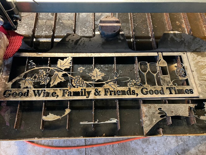
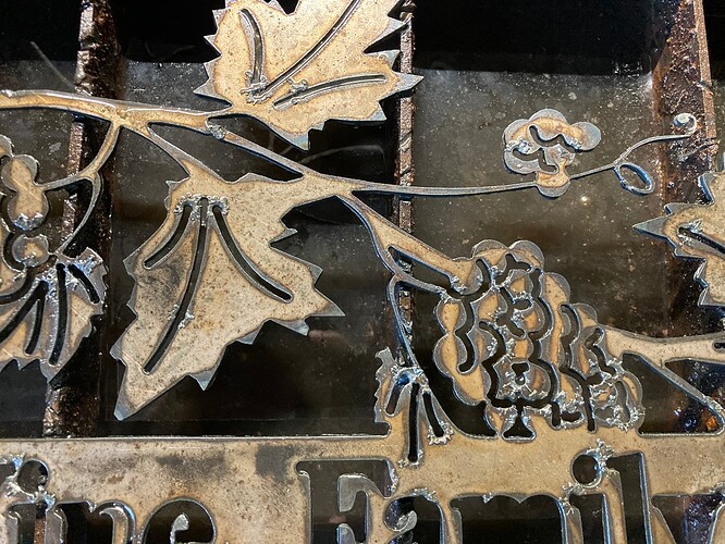
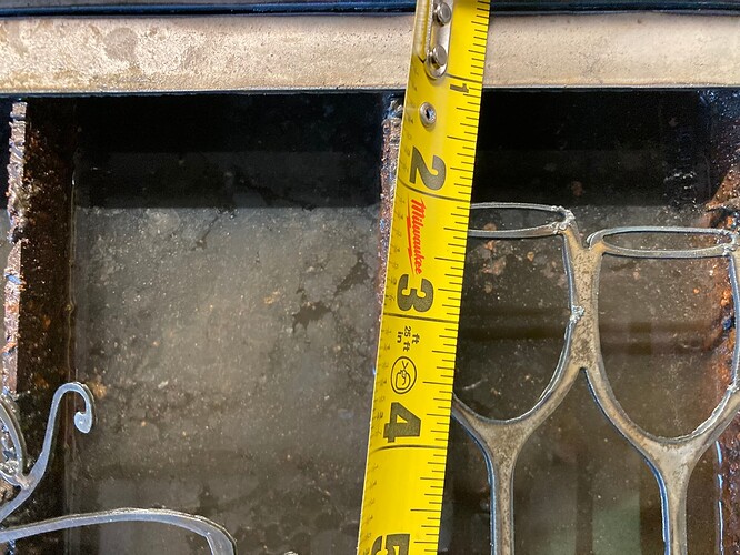
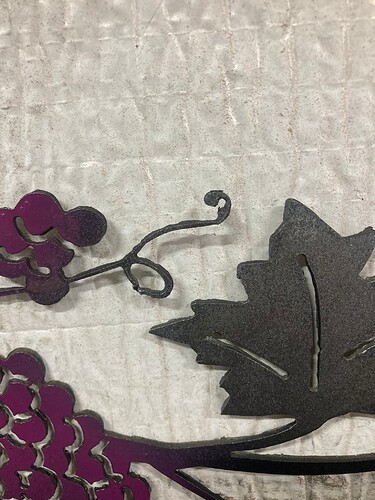
ok. i was able to get a tool path to complete in fusion. i opened the modified file from inkscape, extruded it. moved into manufature and selected the face. the result was not perfect as i scaled it down to 7.5 inches x 32 inches. i wanted to use a scrap piece of metal for the initial test. due to this scale i took the tool paths minimimium spacings lower than my plasma torch is able to achieve…however what i did wind up with i am blown away by. tomorrow i will run the existing tool path again but not scale it down so small. i think it will turn out well. tomorrow i intend to utilize the method described by @TinWhisperer as well. I am interested in a side by side comparison. i have a feeling the cut time and resolution will be better with the TinWhispers’ method but the method i tried today i think might be easier for some of us technically challenged folks…lol. here are some photos of my results today. everlast 52i. 75psi air pressure. 28 amps. nominal THC set to 35 volts cutting on 16 gauge steel at 100ipm. i set my tool path to not have any lead ins or lead outs.
Try using the Simplify operation once or twice on the resulting path. It will clean out a lot of superfluous nodes. The more you use it on the vector, the more you lose nodes so there will be a loss of detail if you do it too often so I generally just use it a couple of times.
is this a command in fusion? where might i find it? is this something applied after the tool path is generated? is there any method to initially doing that to a dxf that is huge like that? @jamesdhatch
thank you
I have not used that feature in fusion 360 yet.
I’ll check it out, thank you.
It’s a command in Inkscape, under Path menu, I believe…
No, it’s in Inkscape. You mentioned that you brought it into Inkscape and then exported the design to be used in Fusion. While you’ve got the file in Inkscape is when to use Simplify.
i tried that in inkscape. it does simplify the path but just applying it one time made the the file unusable. However I did it after commanding it to change stroke to path. Perhaps it would not change the file so radically if I simplified before converting stroke to path?
