As I assembled my table this past weekend. I Noticed a couple things that could be improved on. Not saying the table is bad in anyway, its actually pretty awesome. still have yet to cut, but ill get to that maybe today.
Drain Plugs - I think the brass drain plug should have a 3/8 or larger NPT tap to it. 1/4 is just a bit on the small side, and is asking for debris to get lodged into the hole and prevent fast drains. I ended up drilling out and tapping the plugs for a 3/8 nipple and ball valve setup. it didnt go too well, as the plug just liked to chip and break apart while trying to tap it.
X axis motor cable- I dont know if LS had these motors made to a certain spec or if they are generic size cables that come on them, but i think the motor should have a slightly longer cable so the routing of it can be made cleaner, instead of just hanging off the side of the machine.
cable management- the overhead arm that routes the plasma lead, Z motor and IHC is honestly an eye sore, and makes for an unbalanced and unrefined display. I know higher end machines like a torchmate uses cable carrier tracks that roll nicely to keep the wires behind and away. maybe in the future, and im sure at a small price increase, this could be an option on future tables.
overall, the table was very easy to setup. EXCEPT for adjusting the bearing plates and squaring the frame, which took a substantial amount of time to get right.
I originally posted this in another thread but it fits here as well.
LS, Can you look into possibly adding a plasma cutter “trigger delay” feature in Fire Control? The way it is now I also have nearly a full second delay in my plasma cutter trigger circuit which has to be added to the pierce dwell in the g-code. Under the current setup If at some point I change my plasma cutter all my g-code files are likely not going to perform right and would have to be reposted. Adding a trigger delay feature in Fire Control preserves the files.
Just had a thought that stemmed from Dirty Bills recent post where during a cut his water solution spilled beyond the table edge onto his electronics…
How about an option/add on “clip-on” edge to the left water table edge that isn’t in the way but leans in toward the liquid to deflect would-be spill-over back into the table confines…?
A one piece water table. The two piece water table was a horrible idea. The drains for the two piece are terrible too. Way too small and they stick up too high.
Two pieces is probably way cheaper to ship. Like enough cheaper so as not to double the cost of the water table.
The original drain was too high for me - left an eighth to quarter inch of water when draining it. That’s why I dimpled them before assembly. Now there below the surface of the rest of the tray and it drains to where there’s only a film of water left that evaporates in hours.
If they could dimple them before shipping it would be great. For folks without a dimple die (I got mine for about $25 on Amazon) a golf ball or a trailer hitch towing ball would work as well.
Wasn’t familiar with these so I had to look them up and I see people using those bottle jack H frame presses from them. I have a 20T press but I don’t think the water table would fit. How did you go about pressing the dies?
I plan on using gasket material on the water tray seam. Gasket material is water tight under pressure in your automobile engine. Sure, I will have to cut my own but being an ex-automobile mechanic it should not be a big deal.
I then supported each tray by 2x8s on either side of the hole. I slid the female piece underneath and lined up with the hole. I sprayed both halves of the die with some oil to lubricate as it forms the dimple. I dropped the male side into the bottom piece and then used a 4lb sledge type hammer to pound the top. Not quite as elegant as a press (I have a 20T HF press too but as you noted, the tray is too wide in both dimensions to fit…need the 50T press for that ). I think it took a half-dozen or so firm hits to form the dimple. It’s easy to see that it’s getting equal pressure from the blows by looking at the dimple as it forms in case you’re off-center with your hits. Only took a minute or two for each hole.
The Langmuir fittings fit nicely into the dimple from the 1" die I got.
I couldn’t find any in the 1" size on Amazon (they have the 3/4" ones for Dzu fasteners) and needed it rather quickly so I went with the standard press version. Figured I was only doing 2 holes. I also didn’t want to buy a whole set because it would just end up being another tool getting dusty once I did this one
Good enough for me! I will most likely be doing that if I can’t find one with a through hole. On second thought I might end up milling or turning one… Idk. I know I might never use them again…
I just looked up some drawings. If anyone down the road is interested in that route, it looks like it’s just a .005" clearance between the bore/boss of the male/female pieces and 45° taper. I like the idea of making one with a through hole so I can use my 1/2" impact gun to bolt them together…
Still waiting for my machine but someone with one and a lathe could machine a simple one. Then just pass it around for shipping is all. For a 1-2 time use per person, why not?
I like the idea of sending it around. I have an engine lathe that I had to wire up to a VFD and I’m rushing to finish the PLC wiring before my table comes. More than likely I’ll just interpolate one on my mill. I’ll for sure report back and see if anyone could use it if I do.
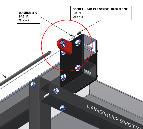
So I’ve noticed since I set this machine up when jogging the X axis I got a whirring(?) noise. I just chalked it up as the X axis lead screw not being perfectly straight so the vibration so to speak was making a noise. Well I noticed today it started on the right side of my Y axis. Further investigation shows the threads on all the lead screws are not deep enough where they connect to the bearings. So the screws that go through the bearings into the lead screws are too long. There was some slight slop on the bearings due to not being able to tighten the screws enough and that was the noises I was hearing. I tried tightening them more but did not feel comfortable, like they were going to snap. So what I did was add an extra washer on each screw and now the bearings have no slop and noises are completely gone. I dont know if everyones is like this but mine was. Heres an image of the washers Im talking about.