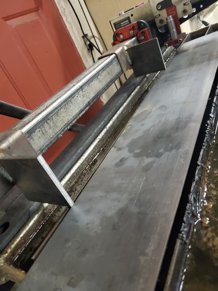
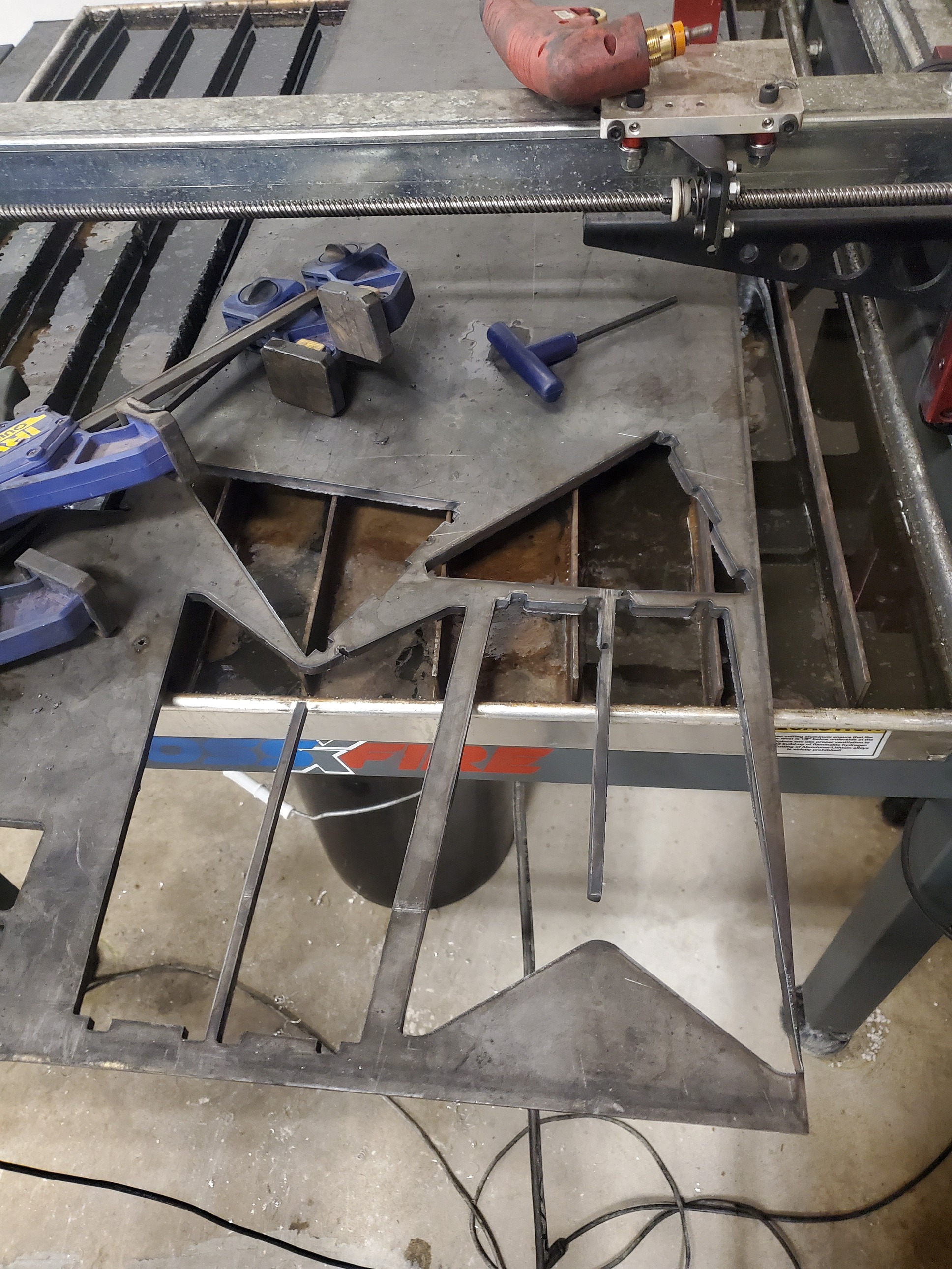
I made these jigs and an edge finder to index plates to the table. These were supposed to be some quick and dirty prototypes for something nicer, but honestly they came out so perfect I don’t think I need to make any new ones. Three points of contact and I can’t feel any rocking against them.
The idea is to align the plate to the XY axis and then if you need to index you can use one of the edge finder ends to locate the torch to a hole you cut in the first setup after you slide the plate up.
Very nice setup. Cut a 55" smooth firewall for my truck build. Turned out ok but wish I had seen this first. Will definitely be building these soon. Did you use as stock piece of tube over the y gantry or have to cut and weld?
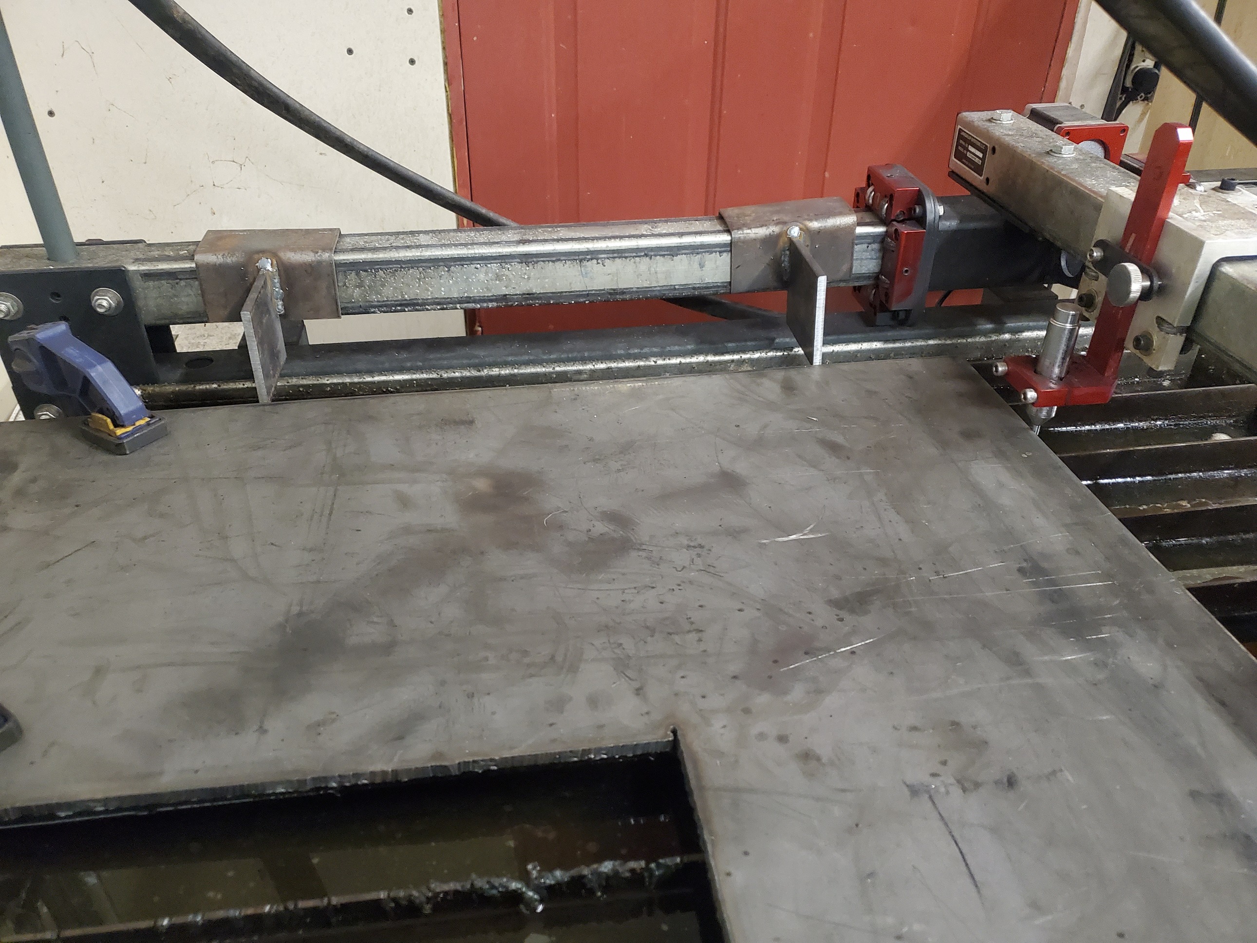
I just bent some 1/8" flat bar into a U shape with a slight bit of interference so its sort of a “spring fit” over the gantry tube. Something a little thinner would probably be better because these are a little stiff.
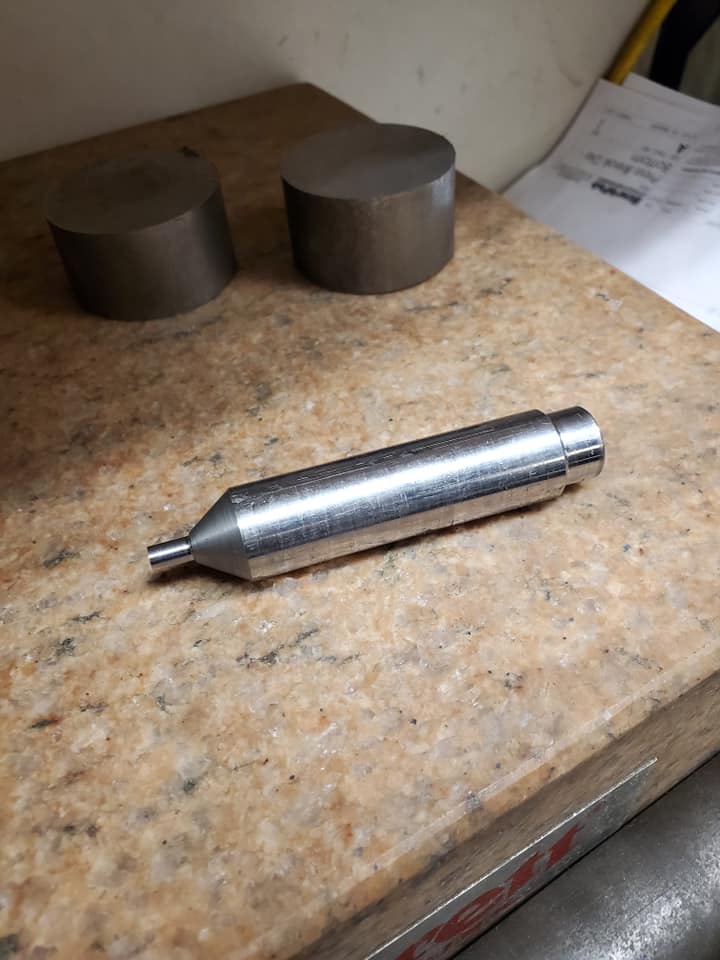
I think I understand how this works. What’s the shoulder opposite from the conical end for? Just curious. It seems to me the conical end is the business end but I’ve never indexed anything so I could just be ignorant. Would you care to share the dimensions?
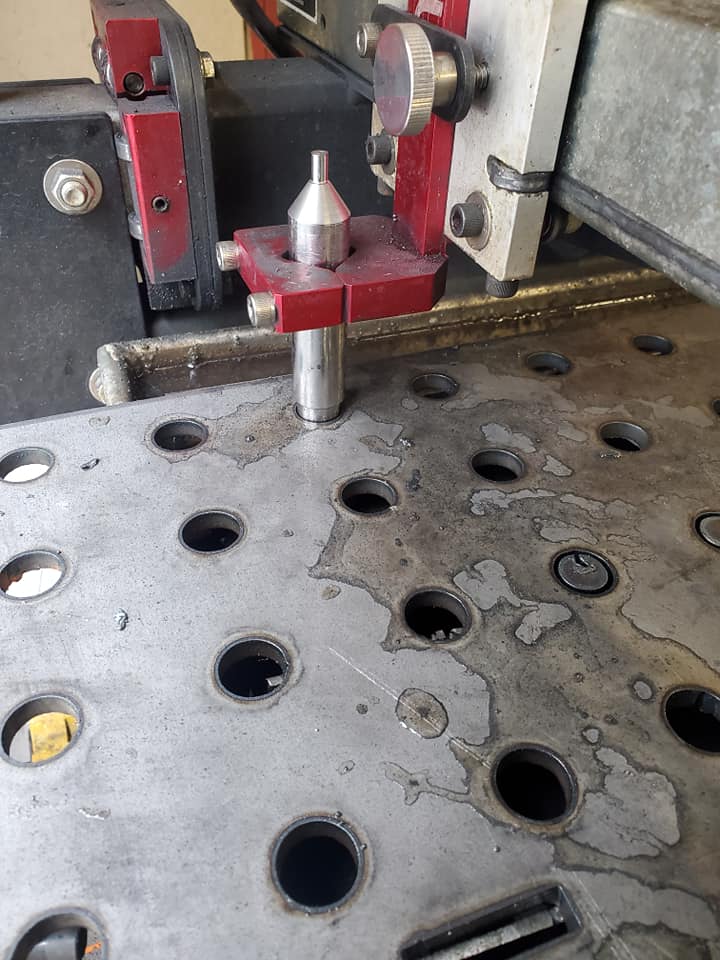
Opposite the conical end is just 5/8" dia, simply because I’m going to try to index some fab table plates with a bunch of 5/8" holes in them. It could be any diameter that fits in a hole in your plate. The conical end tip is a standard .200", so it’s easy to math with.
I already forget the spacer width… I just eyeballed it with calipers and added .100" to line up with the edge finder (so in theory, the torch can cut .1" off the edge of a plate if needed). I messaged Langmuir support hoping they could give me this distance from CAD and they replied with a picture of a tape measure held up to the torch mount and approximate length, lol. Maybe they misunderstood what I was asking for, but my measuring with calipers seemed to work fine.
I’m such a rookie. I guess I don’t necessarily understand because a lot of what you said flew over my head. Lol. The 5/8th thing sounds like an awesome idea. (I have a fixture table and I’ll be using that) Didn’t understand the math you’re talking about or the distance thing. If you don’t want to take a ton of time to break it down for an elementary kid I totally understand. I’m sure there are videos of the indexing process out there somewhere. Thanks for sharing.
Well I haven’t actually put it to use yet myself, but will take some more pictures when I do.
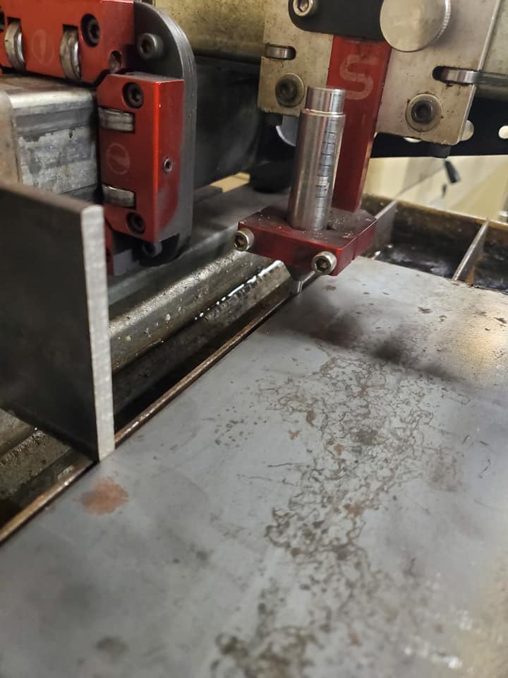
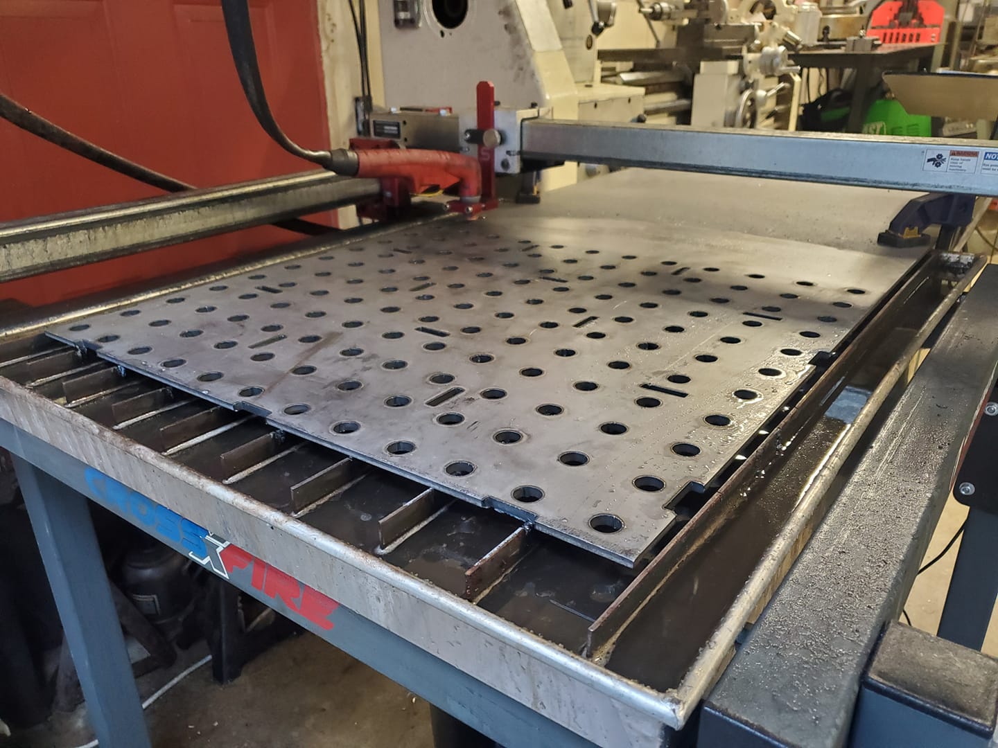
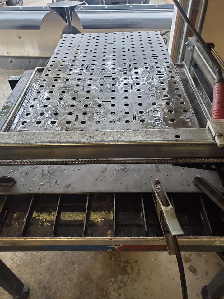
The picture showing the two spacers in line with the .200" edge finder is simply me testing to make sure I sized the spacers correctly (the plate contacts both spacers and the edge finder in that picture). The X carriage is bottomed out against the Y carriage in the picture meaning the center point of the torch is spaced .100" closer to the Y gantry than my spacers, so I can cut off the edge of a plate if needed.
In actual use, the two spacers will constrain the Y axis and then I will use the edge finder to locate the X axis and zero out Mach3 from there.
Once its touching on all both sides, I set the X in Mach3 to -.100" and the Y to +.100". You do this just by clicking the position in the DRO Mach3 window, typing the number, and hitting enter. This is based on the dimensions of my spacers and edge finder. Then you hit goto zero and your torch should be centered over the corner of your part. In Fusion, I’ve made this same corner the origin for my CAM setup.
Pardon my ignorance, but how did you get the spacers to match? To me welding is something that will attach two pieces of metal ‘sort of’ where you want them to be…
Well as I said they came out better than I was expecting. They were originally intended as prototypes and I was planning to machine something more precise or pop these on the mill to tidy up. But just the bandsaw cut seems to work great for this purpose. As shown in my first post, I can’t detect any difference in them. If you think about the application, within 1/16" would probably be fine and they are definitely better than that. As long as you fit the two pieces nicely without gaps, the welding shouldn’t move them enough to care for this application.
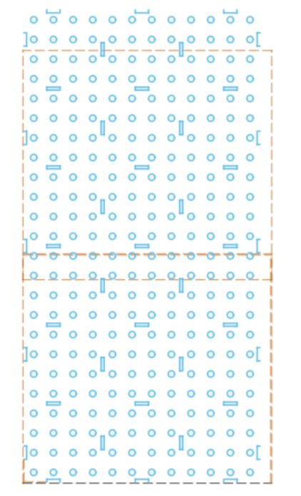
This shows how I laid it out in CAD. The construction lines are the working area of the Crossfire. I have three CAM setups, where the origin is one of the previously cut holes.
Ah, ok, thanks! I’m interested because I have a project coming up where I’ll need to cut a single artwork out of 72" blank. The tricky thing in my case is that I’ll have to break paths at the sections so there will be no ‘outside’ for SheetCam to control offsets. I’ll have to make sure cutting direction is consistent all the way around and manually offset. Not a big deal, but I don’t want to compound the issue with significant accuracy errors on top of everything else.