We have a Crossfire Legacy on loan at the local MakerSpace. I’m having some trouble getting it going.
I have a simple case which is supposed to cut a square with some holes in it. There are some oddities with starting cuts, and not completing shapes… but that is a discussion for another day. We are using LazyCAM, and it is another challenge.
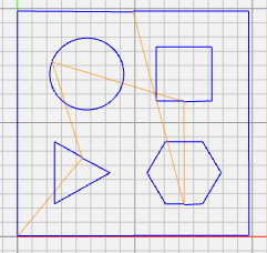
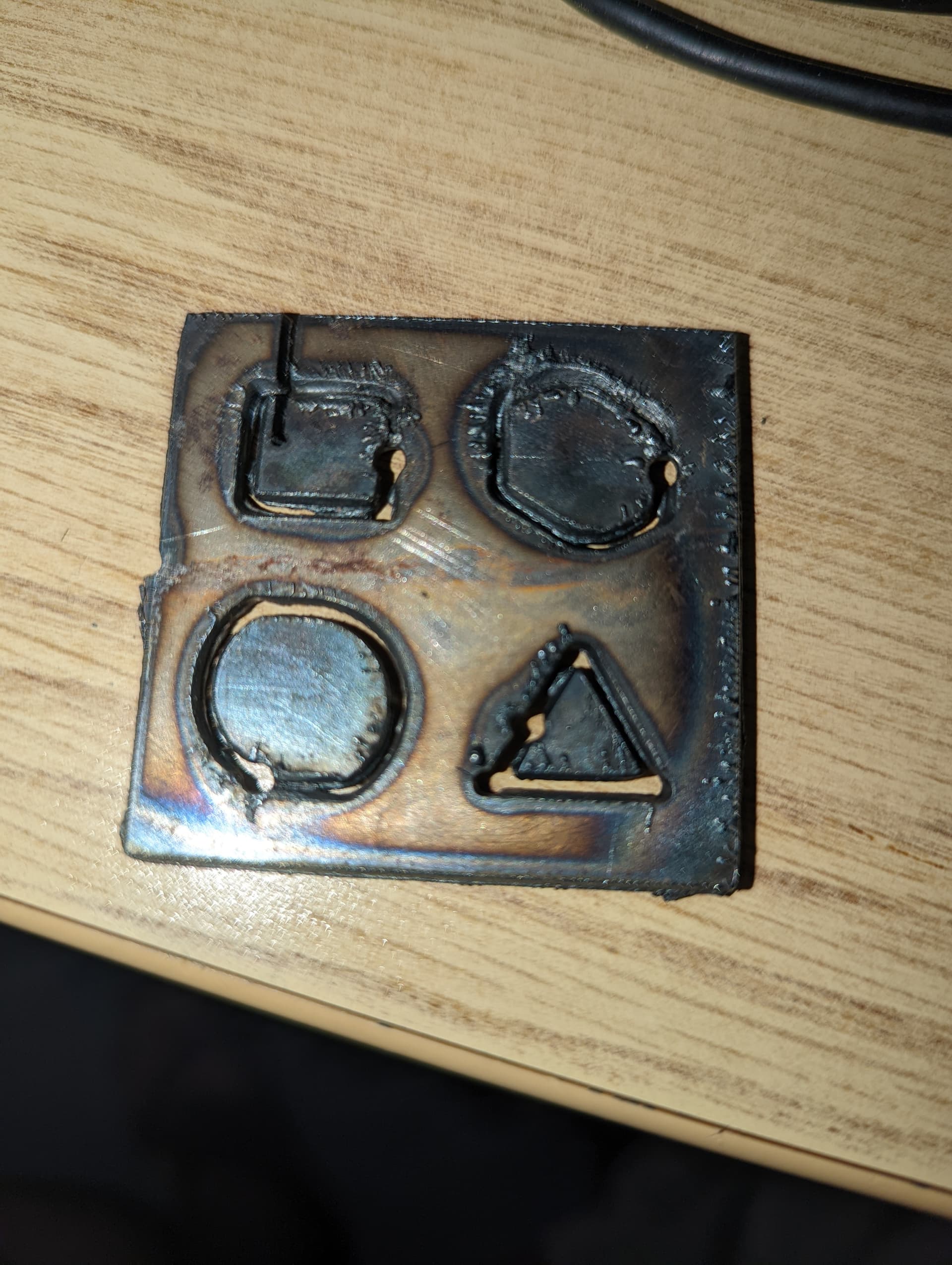
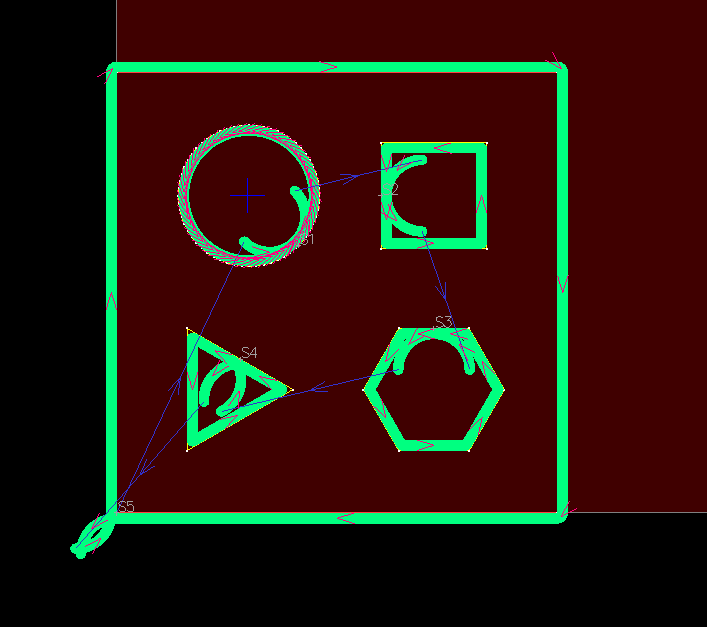
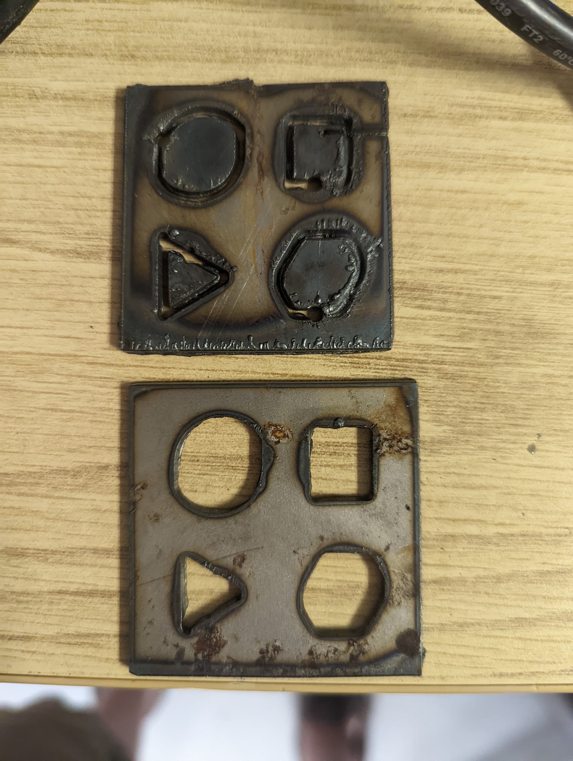
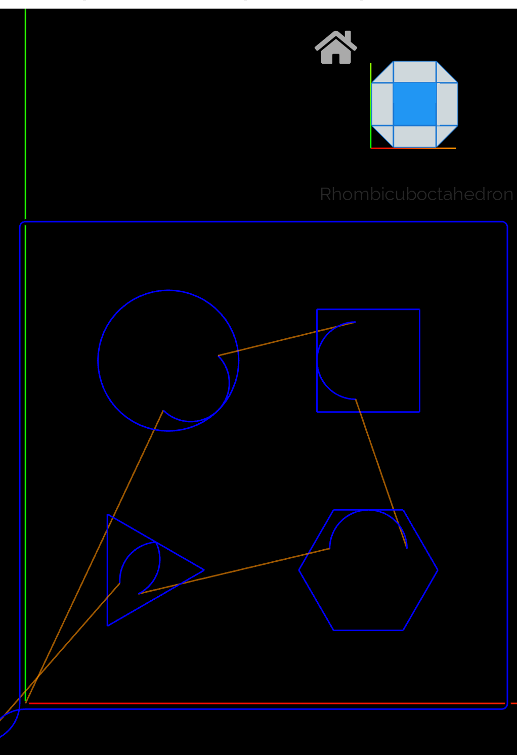
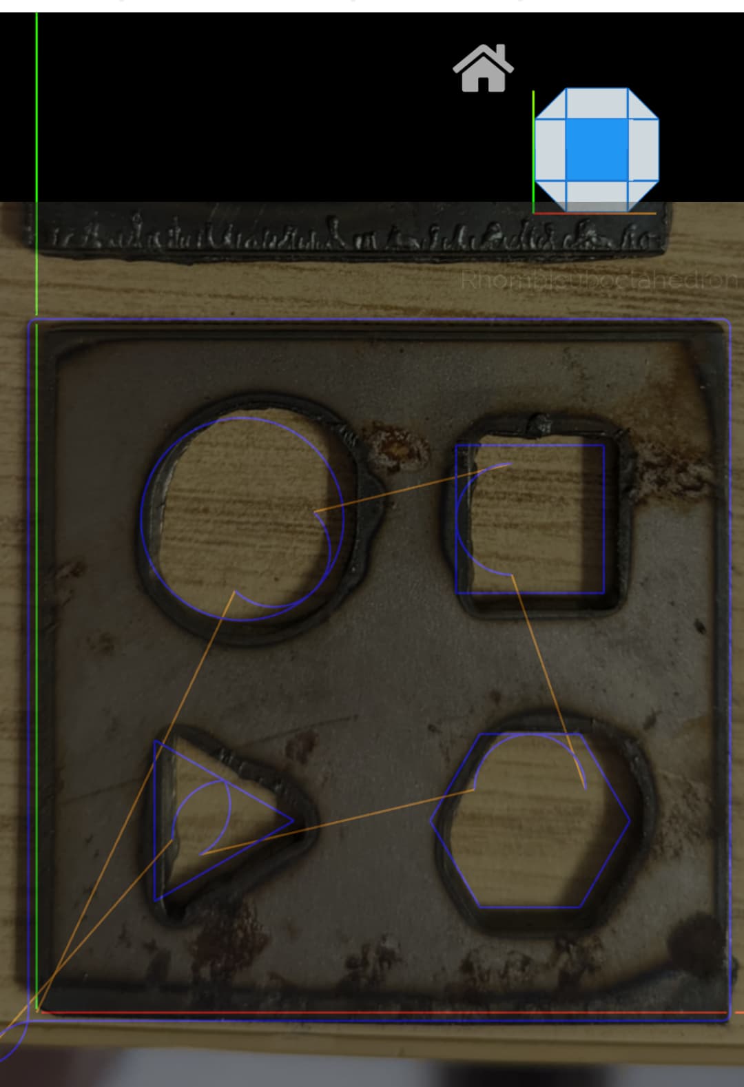
The first issue I’d like to solve is the distortion of the cutout shapes. The circle is repeatably distorted. The hex is repeatably distorted, and not close to closed. The square and triangle seem to be as expected. (Please ignore the stray cuts. There were other failed tests on this sheet)
I will try to attach photo and gcode. gcode looks fine in gcode viewer/simulator.
I do not think motors are slipping, since pattern is repeatable, and perimiter is cut after holes, and it seems to be as expected.
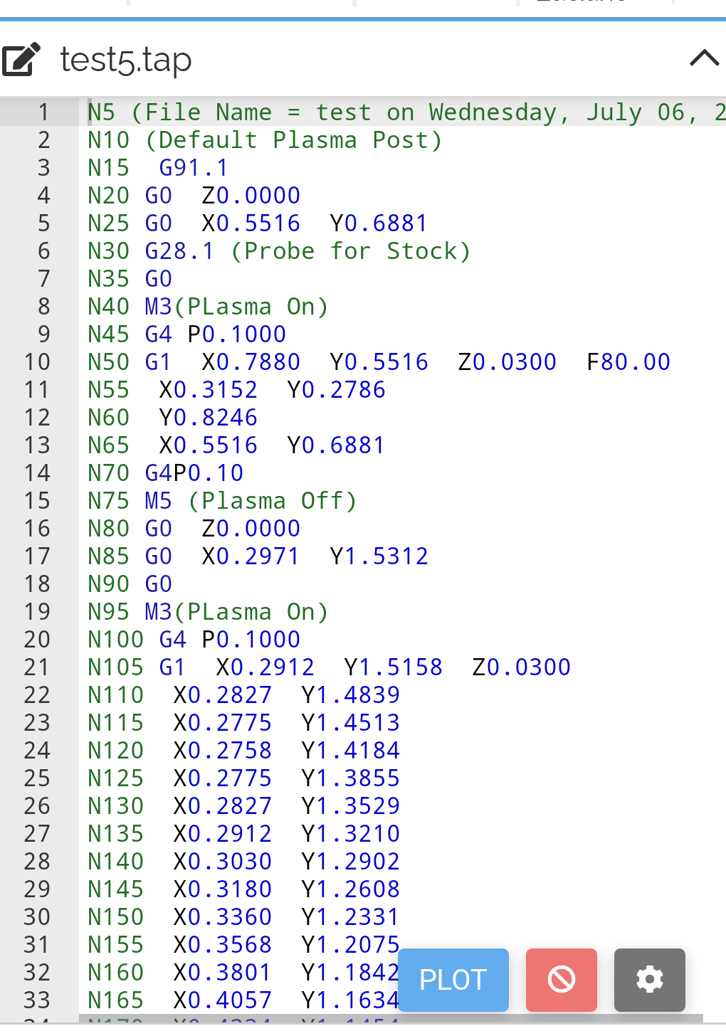
Perhaps someone using Mach3 could confirm, but I suspect that the G91.1 incremental arc mode could be the issue with the odd shapes. In Firecontrol, we use the G90 absolute coordinate system.
The pierce delay of .1 seconds, is probably too short.
Yes, you’re absolutely right, that command set IJK to incremental mode in Mach 3. However, since all the moves I can see are G1 moves, that wouldn’t be a factor. There are a lot of things wrong with the GCode (Use of Z axis, for instance) and that the basic cuts are terrible, that I’d move back to basics in this case and hand code some basic squares and tune the setup first.
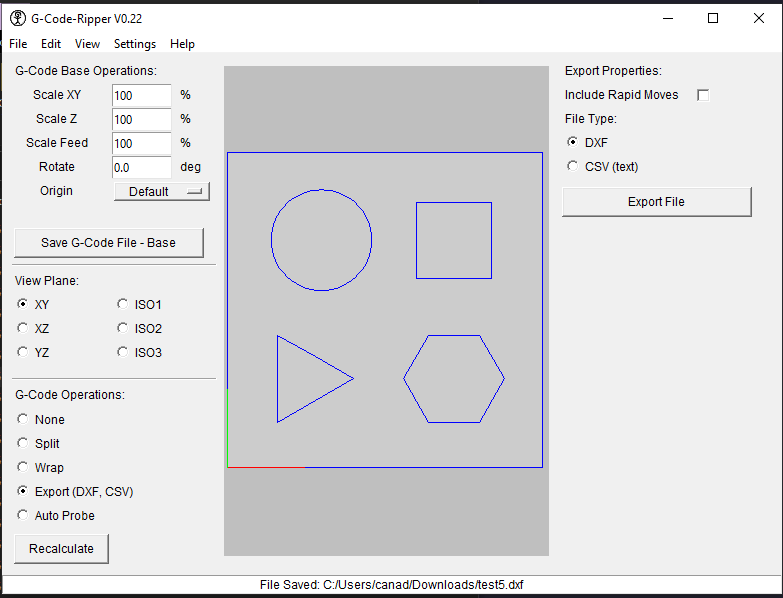
@Mr.What , post the geometry file (either as SVG or DXF) you’re using and I’ll post process it for a Mach 3 system.
Thanks @TinWhisperer ,
Here is the tap file… test5SheetCamMach3PlasmaNoZ.tap (3.0 KB)
Note that this assumes that your Mach3 Dwell settings for G4 is in seconds. (Which, IIRC, may be an issue with Mach3)
UPDATE:
Here is the same file, but with a post processor that corrects the dwell to Milliseconds. test5SheetCamMach3PlasmaNoZ_MS.tap (3.4 KB)
60 in/min. I re-ran at half speed, same exact distortions. Same g-code, but half-speed setting on Mach3.
The torch is in good shape. If I turned up the current, cutouts would have fallen through. I was cutting thinner guage plate earlier.
LazyCAM. I need to learn how to do those. It was not my priority, since I don’t think it should effect the distorted circle… just that little extra “hole” at start/stop point.
Will run. Perhaps tonight. What post-processor are you using? I’m trying to refine a path from .dxf (or .svg) to .tap. LazyCAM seems to be an orphan. Since this is a MakerSpace, with equipment on loan, I want to exhaust open-source or free options before we get into more licensed software.
The post processor is noted in the filename and in the file itself. However, it is a postprocessor for SheetCam application. For this small example the demo version will work for you. My settings were for 11Ga CR steel. You may have to adjust for whatever material you’re using. You can manually tweak the .tap file, the key parameters are:
“G4 Pxxxx” sets the pierce delay in Milliseconds - MAKE SURE you’re Mach3 configuration file is set to use Milliseconds for G4 Dwell. Anything else is useless.
Fxxxx sets the Cut speed in inches per minute.
On that system you need to set the cut height manually with a shim. Proper cut height is around 0.063.
Well, baby steps, things are improving. #1 you’re making it harder to tune because you have such small shapes. Plasma Cutting, especially one that isn’t tuned well, doesn’t DO small very well. I’d suggest an overall size of your test pattern no smaller than 4 inches. #2 the consistency of the distortion is actually a good thing. We can work on that. #3, it appears, although tough to really see with these small shapes, that your bevel is on the wrong side, almost as if your swirl ring is upside down. I could be wrong about this, but that’s the impression I get.
Next steps.
Check the size of the outside of your object, How close is it to the intended size?
Make your design bigger so we can focus on big issues first. Fix those and then tune it.
I’d check the Mach3 motor tuning parameters. Distortion could be caused by poor acceleration parameters (assuming everything else is tight). I don’t have a Mach3 setup where I am, but I might be able to read a config file. Look at each motor settings and let us know what they are.
Coupler slip tends to be cummulative. Weird thing is that the shift seems consistent and biased to the right side so even acceleration error doesn’t make sense given where the different lead ins are.
Almost as if there is some drag in that direction. Could be some kind of looseness in the gantry bearings and the torch cable is dragging too much in one direction…
Increase air psi to 70 and imp to 100, give settings a try. Don’t know what plasma machine you are using but looks like torch is melting out material because of low air psi and moving to slow.
Is cumulative coupler slip consistent with me getting a pretty good perimiter, which is cut last? Outside dimension seems to match drawing as close as I could guess, given that my cutting parameters are not tweaked yet, I don’t know my kerf, and I don’t know if the kerf is symmetrical.
Acceleration parameters, some sort of setting “aliases” simultaneous movement in both axes, or the power hypothesis (both motors cannot step at the same time) seem most likely problem to me.
The distorted shapes repeat reliably. Any suggestions for experiments to check this? e.g. rotate test pattern 90 and/or re-order little cutouts and check distortions?
Important background:
cutter was working better, but perhaps not as good as expected, in recent past. It had rounder circles of similar size as part of more complicated .tap downloaded from internet. Many circles. Small, but same distortion. This may have been on a different computer. I don’t know.
Computer is a mess. considering rebuild. Was scanning itself into uselessness. Removed some bloatwear. No longer scanning itself unresponsive, but we lost use of Ethernet AND Wireless NICs. Win 7 upgraded to 10, running Mach3 which mentions support for nothing newer than XP. I think we are 64-bit. I hear Mach3 is likely 32-bit to get parallel port support, which we don’t need for CrossFire
As I mentioned before, give us your Mach3 Motor tuning settings and I’ll compare them to what I have in my config file (I’m not going to bother with this if you don’t provide the comparison data).
Check the Stepper motor current switch settings. X Axis should be one setting lower than Y (I don’t remember what they are supposed to be).
If your computer is constantly scanning, disable Indexing on it’s drive.
Mach3 is only 32 bit.
Re Kerf, the file I sent to you assumes 0.047" kerf. This will be close to what you probably have so don’t worry about that at the moment - you have more ‘interesting’ problems to work on.
To share settings… do you want a screen capture of the settings dialog… or is there a file I can copy? I’m new to Mach3, although I have worked on Marlin, Smoothieware, Grbl…
I’m away from the machine now, but might go in tonight. Thanks.
I am looking for another laptop. I don’t know exactly what I need to migrate Mach3 to a different machine. Is there some DRM for CrossFire linked to some sort of serial number, or MAC address?