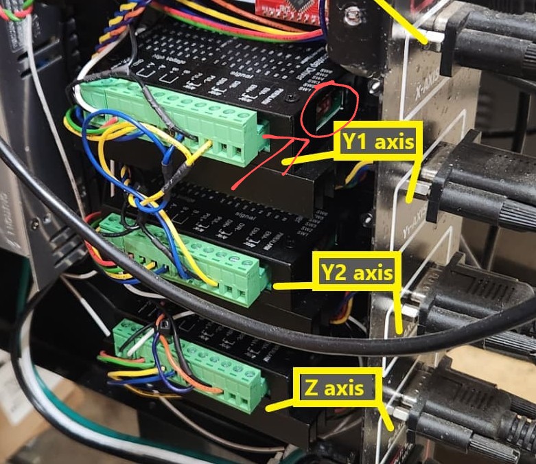
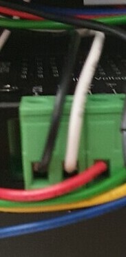
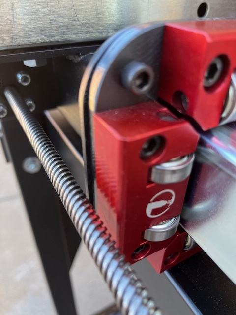
The ground wire on the upper Y driver is on the positive pin.

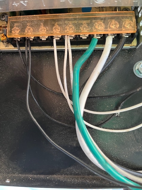
Follow the black and white back to the power supply. Make sure which one is neg and which is positive.

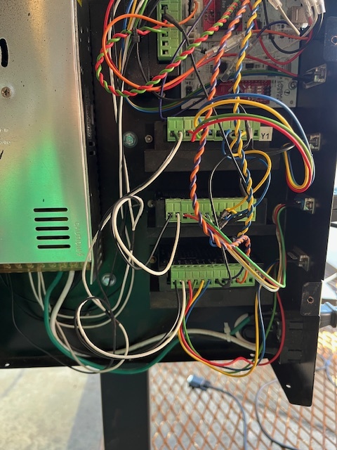
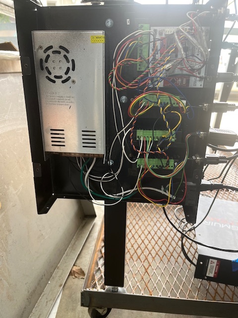
thanks for finding the ground white black issue , weather here truned bad so will have to wait a bit to get to this again . The only way a I see to check dip switches is to take panel down and remove drivers from panel . yes I have the plastic part installed
the only way to check dip switches is to remove from panel , will try that later
Take care, it’s been raining in Chattanooga for 3 days. Make sure that isolation plastic screw bushings are installed correctly with the dog bone behind the panel. After we get this fixed, we need to figure out what makes the chassis connect to the control box.
Let’s get this done first.
Thanks stay dry
You should be able to see the switches without removing them. All but the second switch should be in the up position.
thanks , I maybe able to just make sure by feel that the dip swithes are in the correct loaction
A dip switch had moved on me at one point, and threw me for a loop.
It’s easy to visually see the position without removing them. Takes 2 seconds since your pic 3hrs ago shows the panel removed.
ok todays up date the wite lead in one picture above was in the correct spot , all the dip switches are correct . Changing the y1 motor and the x motor did not change anything. I took the x access rail off made sure all was square . Now I tried to run just Y and all moves good , the problem comes back when I put the X rail back on
I have been posting on the facbook site as that is where I could get the video of what I’m dealing with . Most all the answers I’m getting is square and level , I have measured from corner to corner and within 1/16 , have not checked anthing level it is on a cart with stock feet
after having a dream last night about why the x access moves and gets off parallel to the y. This is a project and was missing some parts , I was out of the tube spacers after the frame assembley so I did not have 4 left to do for X . Maybe that is keeping it from getting tight and allowing it to move ,
parts ordered SB here by Wed
I know exactly what you mean. When I was 17, my brother and I replaced the competition clutch on my Heavy Chevy Chevelle by following instructions on a Chilton manual. It was the middle of winter in Fairbanks, Alaska. The garage was unheated and probably close to 10 below.
I wanted to save money so I felt we could get by without the alignment tool ($11). We did not lift the car up at all for fear that with our inexperience, it would fall on one of us. So I was skinny enough that I could just skim under the transmission but no other movement. We worked on that for more than 9 hours but the best we could do was get the transmission nearly in but short by about 3/4". We finally gave up and went to bed.
I woke up about 4 am and had a thought: Things must be off by just a little bit and the throw-out bearing and clutch disc must be somewhat stable. I then theorized if one of us got in the car and pushed on the clutch pedal, the clutch disc would be free to slip around. That is exactly what I did: My brother stepped on the clutch and I kicked on the back of the transmission forward with both feet. To my amazement IT WORKED! An hour later I was driving my car again.
yes dreams are what get me back on the right track and out of the rabbit hole
Got the tube parts today and installed but did not solve my problem. It was square and level for this test . I’m at a loss for what is wrong , so I think I will start over a step1 or sell what I have and buy something done and working
That driver is wired incorrectly. Confirm that the white wire from the VCC terminal of that driver goes to the positive of the power supply, and the GRD terminal ( black wire) of the driver goes to the negative of the power supply.
The picture you took and posted of the 3rd driver from the bottom is wired wrong.
I will go check them again before I take it all apart , the last I looked they all look like in the same place
I did not change those power wires , from the start I only changed the 4 color wires to make both Y1 and Y2 look the same. If you think it could be a driver issue it came with 2 spare drivers y1 and y2 marked