Langmuir could probably give you a wiring schematic and you could trace it out. That picture looks like the lead screw was burnt. My bad. Good luck to you.
1 Like
Thanks , I’m going to send a message to Langmuir and ask for help I have asked here and on the face book group and nothing has worked for this problem so I hope I can get help
1 Like
after more of messing with connections I got the y2 to work and run a brake in file . The file shows that the bearing all need a bit of adjustment to get this to run smooth. I still need their help with the z port
1 Like
So the issue was a mechanical one and not electrical?
If Z axis isn’t moving, basic troubleshooting would be to ensure the motor spins. If it does but the Z axis leadscrew doesn’t move, then you have a loose coupler.
1 Like
just an update to my build process , seems like I continue to have trouble. So I will only work on 1 thing at a time untill I get it right.
Y acess.
The Y1 moves a little before the y2 does , I have an open ticket with Langmuir and waiting for suggestions
Switch the motor connections to see if it moves to the other side. Check for burnt pins in the db9 connections. Make sure the couplers are tight.
Mark the lead screw and the coupler with a Sharpie to see if it’s moving.
2 Likes
so you suggest to switch y1 and y2 to see if it changes witch one moves first ? and the mark on the coupler and lead screw is to check for slipage
1 Like
Yes, that will isolate the problem
not sure how to show the video , but I sent in to langmuri support how it moves and bindes up ./ It starts out fine and then the y access gets out of square
anyone close to Norwalk ca. want to finish this setup ? for $
Upload videos to youtube and post the link here.
Did you switch the Y cables on the control box?
Did you check the couplers for slippage?
Did you check for burnt pins on the DB9 connections?
Has this table ever worked since you bought it?
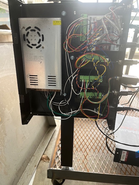
Post some pictures of the control box with the cover off.
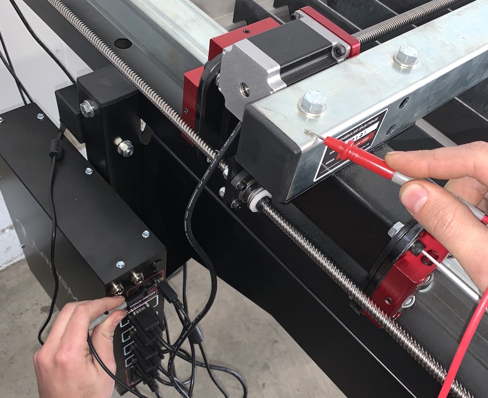
One last thing, do you have a working multimeter?
1 Like
yes y cables changed , did not see slippage did not see burn pins , table was never built just parts when I got it , I have posted picture of the cover off . and yes I have a meter
Check the power supply inside the control box for 36 vdc. + and the - screws. DC
Check the usb printer style shielding to the table chassis set on continuity. Should be open.
Laptop or regular desktop computer?
The picture you posted was a closeup of the drivers. Need to see the whole thing.
When you switched the Y plugs did the problem move to the othe side?
I have continueity from box to frame
also no way to check dip switches in the control box with out taking them out
Did you use the isolation bushings when mounting the control box. It looks like a plastic dog bone or boomerang. The contro box must be isolated from the frame electrically. That is not your problem at the moment but, will if we get this thing moving correctly. Did you check the DC voltage at the power supply? 36 volts dc.
If you didn’t have any slipping of the couplers, you need to check the dip switches on both Y drivers to make sure they are the same.
1 Like