Here you go. Just change your plasma cutter.
TINA BENSON - COWBOYS SIGN 23X23 - HENSEL v36 v1 bigdaddy216.f3d (3.5 MB)
This was setup for Crossfire Pro. You will have to change it to Mach 3. I wasn’t aware you were using Mach 3
1 Like
Had several small line sections underneath other lines.
If your lines don’t turn black, there is usually a problem somewhere in your drawing.
You need to zoom in on your drawings to see if you have any loose or unconnected lines. You can not see them, but Fusion can.
Also downloading Sketch Checker into your add on’s into Fusion. It will mark all the bad spots with blue dots.
1 Like
For what it’s worth, change your Pierce Clearance to 0! Pierce Clearance is added to your lead-in / lead-out. If you have a Pierce clearance of 0.15 and set lead-in to 0, you get a .15 lead-in.
I noticed some contour problems (cutting on the outside of the mounting holes, for example.) Once I cleaned those up, the .nc file from Fusion (with FireControl as the post) loaded fine in Mach3.
What post are you currently running in Fusion?
1 Like
The Mach 3 post processor from cam.autodesk.com suffers from the same error. When trying to post multiple sections, it leaves out the M5.
Here’s Autodesk’s Mach3 post with the changes made.
mach3 plasma - Mod.cps.txt (17.0 KB)
Rename without the .txt and Import into your post library within Fusion.
1 Like
Looks like you got some great feedback from others as i expected.
Not sure what steel thickness you plan on using but this top part on the helmet might want to fall back or hangout with no support. might be OK since its 17’x20".
Going to be very cool! You going to light it?

2 Likes
It will be 12 gauge. I never had anything show me that I had broken lines. It extruded fine, and all the cut paths worked when I set them up. Only had this problem and I went to cut it out.
As far as I know I’m using the same post processor I’ve always used for Mach 3 from the langmuir website
You’ll be fine with top of helmet if 12ga. GL
Still don’t work. Took your version of my drawing put it in fusion still will not create cut pass for the holes or anything else… About ready to pull a hair out of my head
I dry ran the whole sign without a hitch.
The 4 holes in the corner need the lead in and lead out turned off. Set the cut direction to center.
Your kerf size maybe to large for a clear tool path. It could be the Mach 3 processor that’s your problem. I’m truly sorry for all your problems.
Like I said it ran the entire sign for me. My kerf setting was . 057.
2 Likes
Do you know if this is still available to download? I’ve looked and cannot find it.
Maybe only with paid subscription?
It looks like it has moved to GitHub
The installation directions are pretty good. I don’t recall having any issues with them.
2 Likes
That is it. Just add into fusion Add in tab
Search Google you will find it
1 Like
So, what is the consensus, then?
It must be something in our (@mdmuss and my own) systems causing Fusion to fail to create these tool paths, right?
@mdmuss, have you created a ticket with Fusion support?
I’ve yet to have the M5 g-code issue and I’m still on the v1.6 post, and my typical work-around to the tool path issue is that I’m creating about 5-6 separate tool paths for a given design, loaded into the same g-code file.
The open lines that you guys saw when you looked at my designs don’t show up on my end, and haven’t effected me generating a tool path on those single contours, which is very anomalous.
I have done a full factory reset on the machine (i7 3+ghz 16gb ram 12gb 3D graphics card on Windows 10), and downloaded a fresh copy of Fusion, to no avail.
The ONLY thing that has given me any indication of the where the problem might be stemming from for me is reading on the Autodesk forum that some users have had issues with my same Nvidia GForce graphics card, but I’ve yet to find any specific threads outlying what those issues were…
Very frustrating. Especially since this has been a new issue, for me, post update, and before it was all working fine.
1 Like
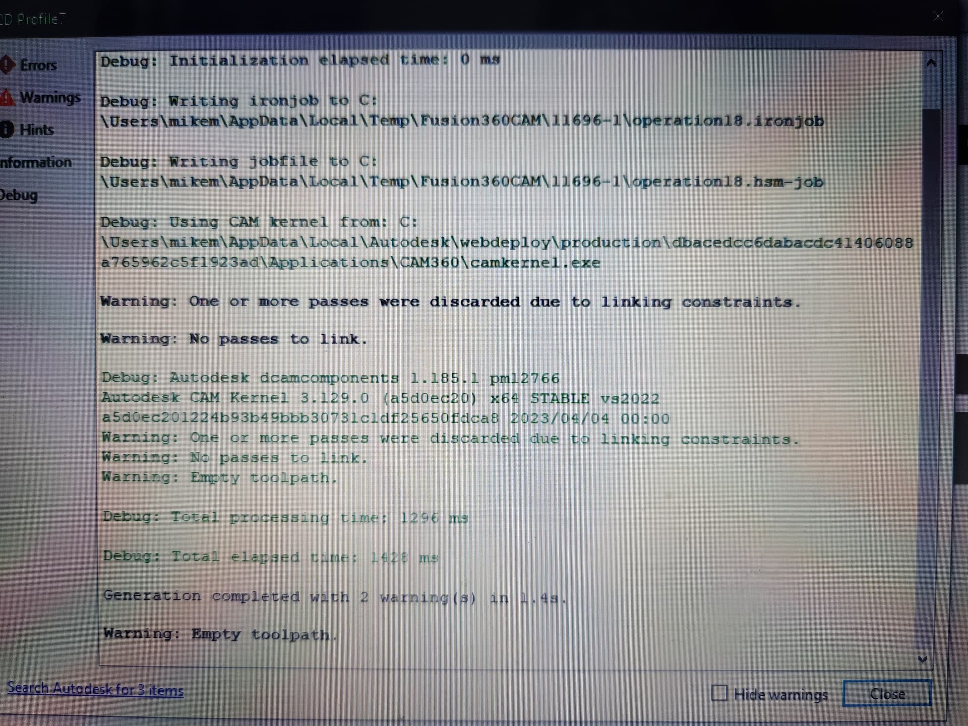
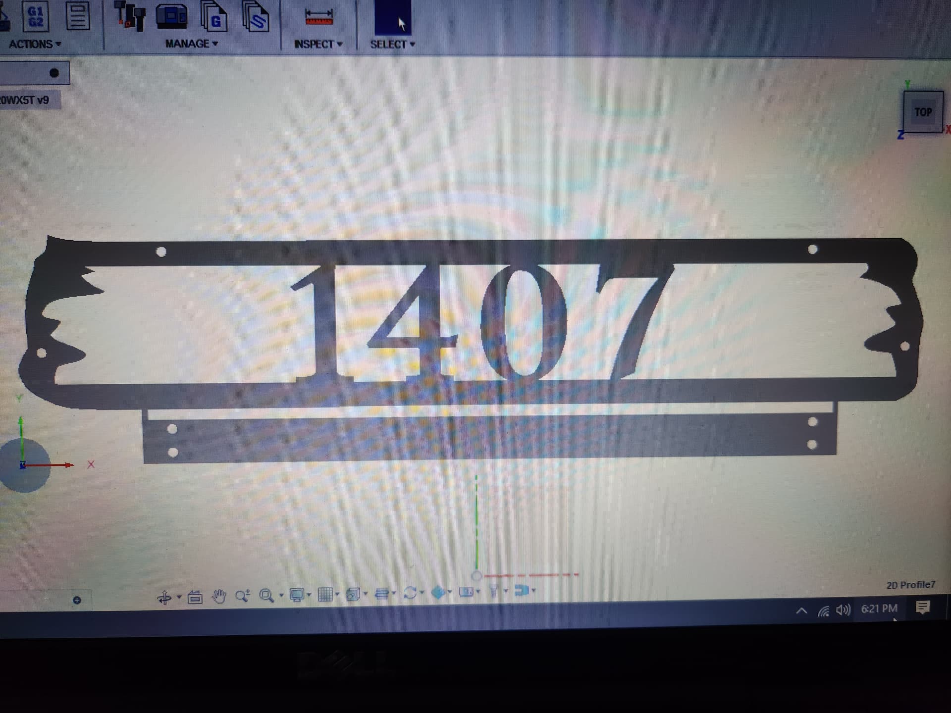
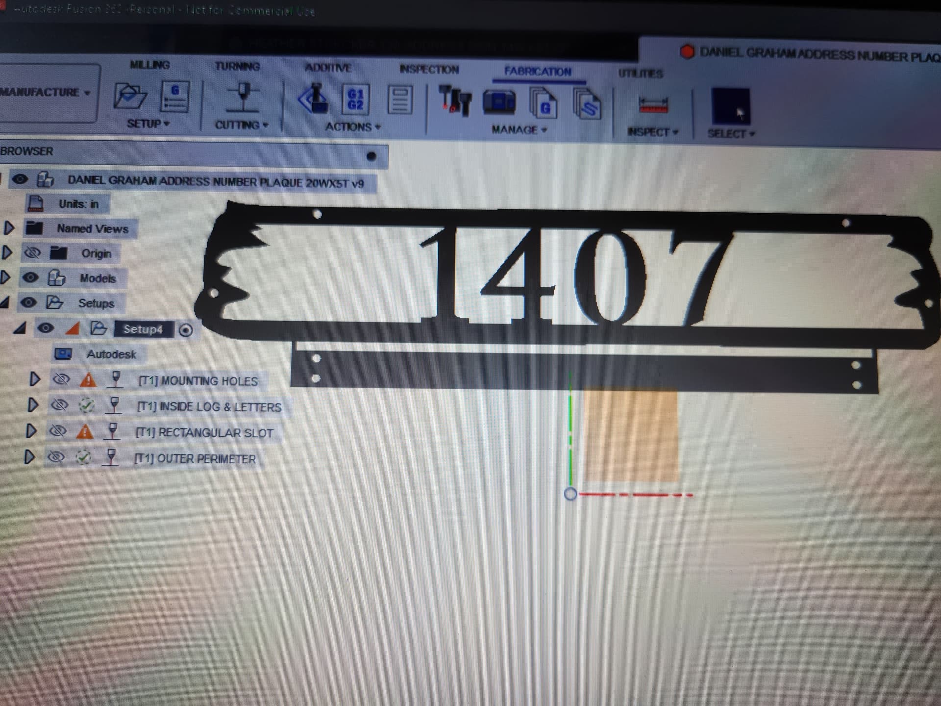
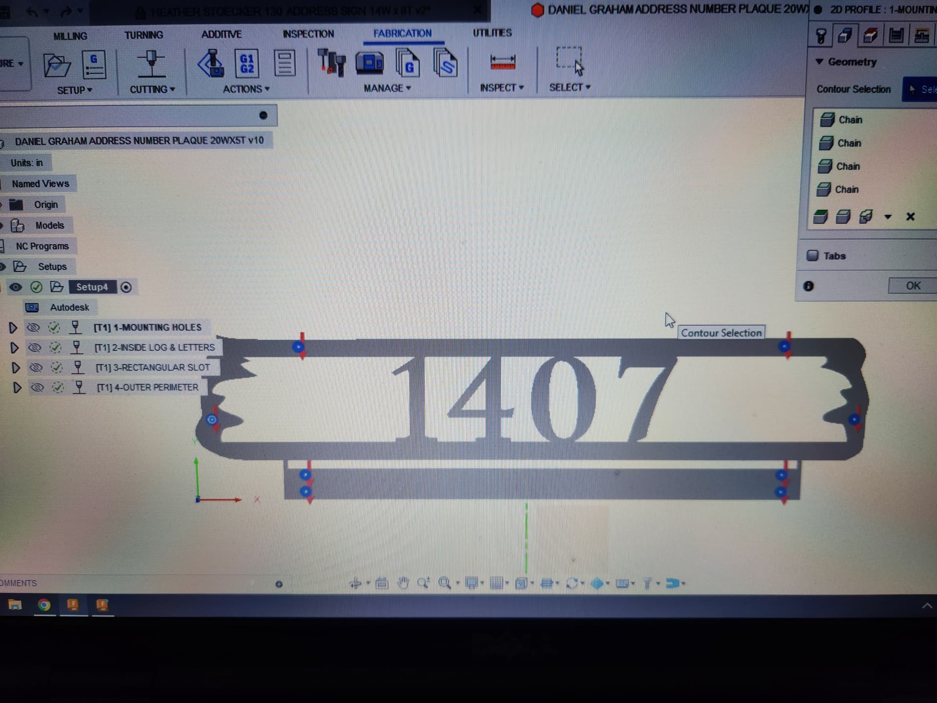
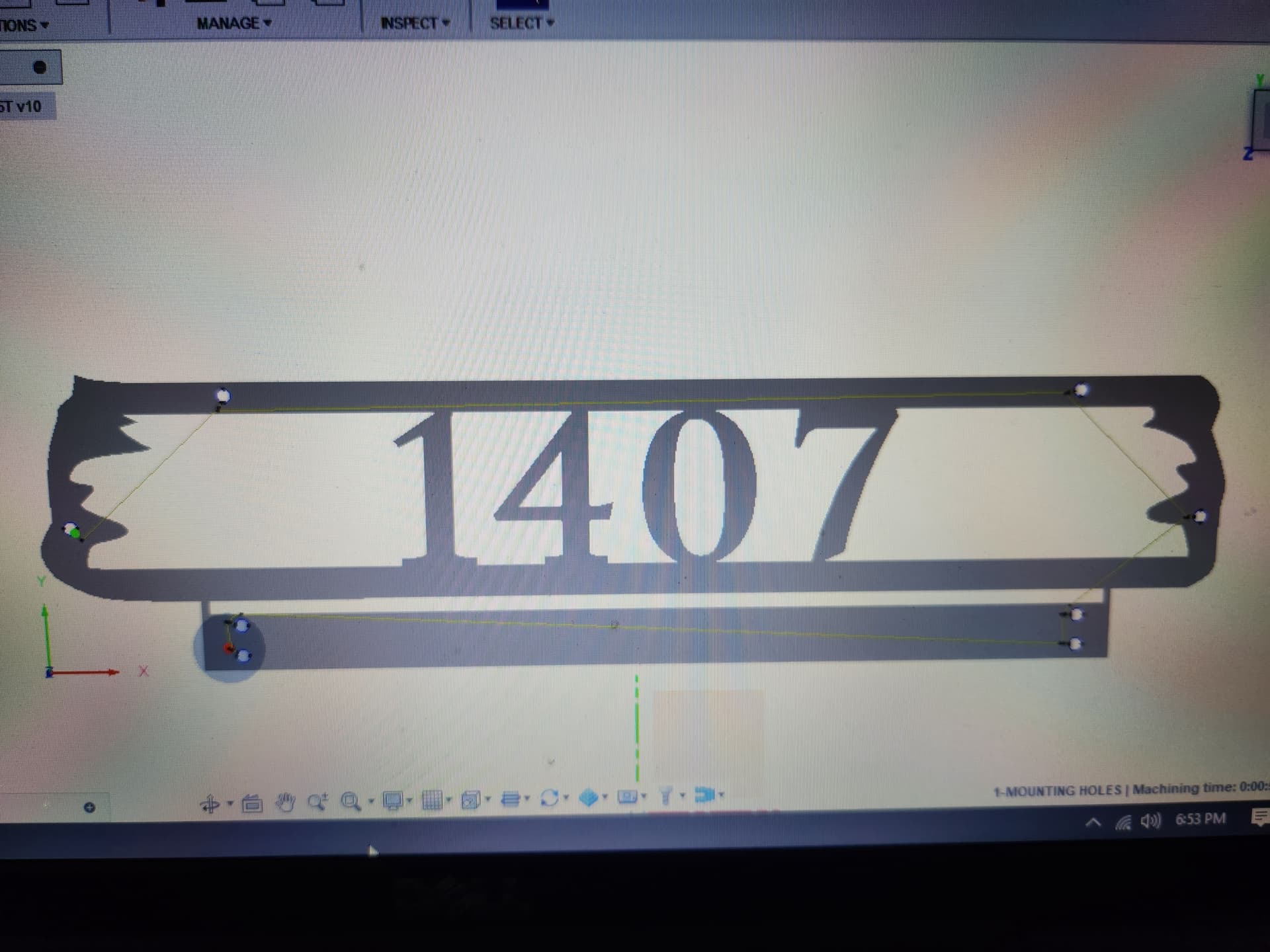
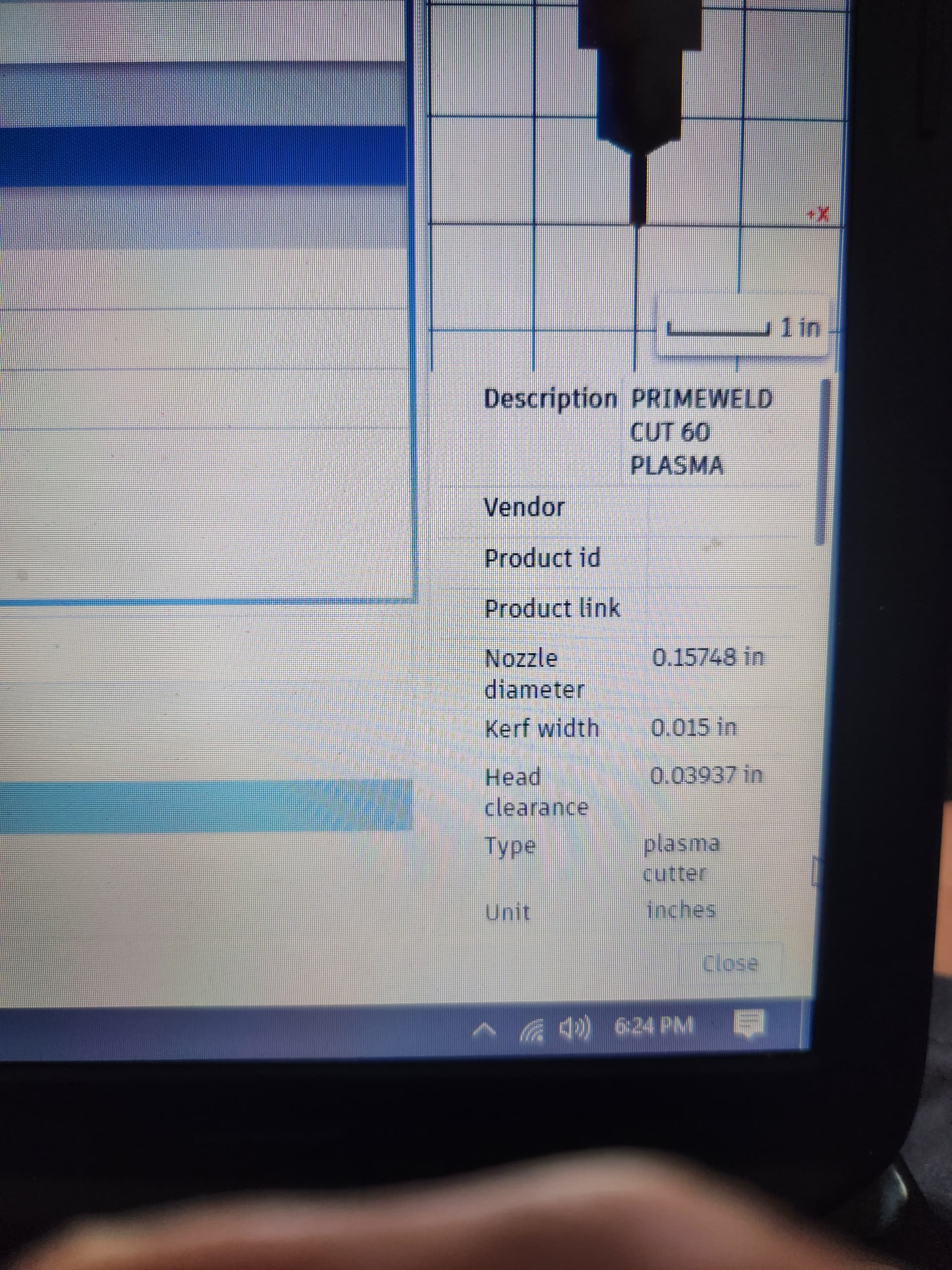
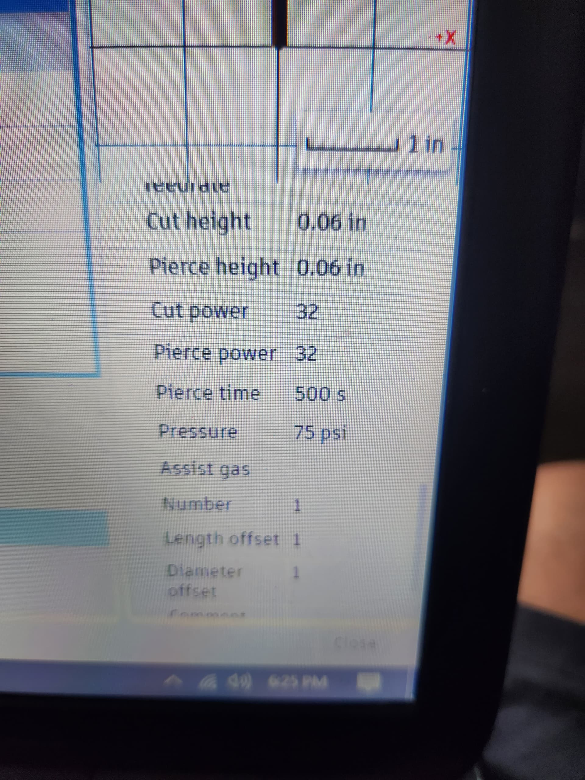
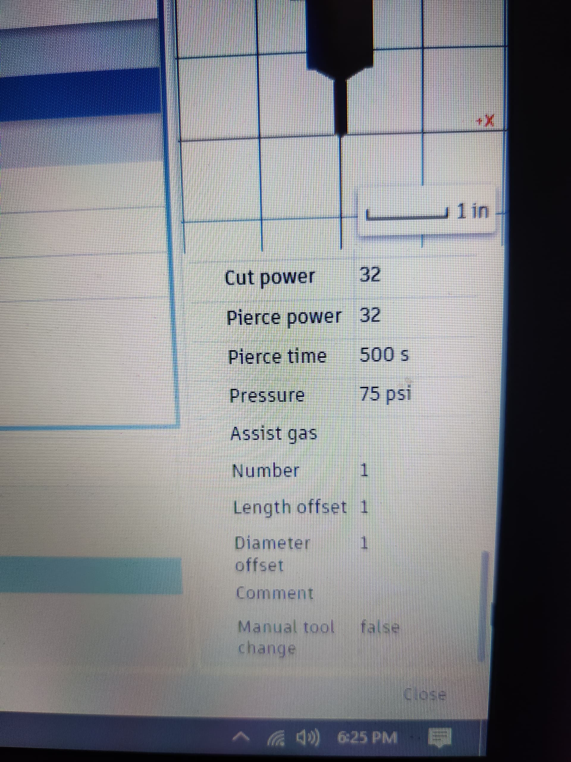
I’m still fighting it too something in there has changed. Here are some of my settings The 1/4-in hole and the long 1/4-in slot in the drawing will not create toolpaths on inside or outside cut with or without lead in and lead out doesn’t matter what I do…
Software will not allow me to create toolpaths for simple things like .250 diameter holes and .250 rectangular slots
see pics below
save your file exactly how it in now and Export an F3D.
Then well have your manufacturing info too as you posted above.
2 Likes