I introduced myself in an earlier post, and since have been doing much work on assembling the CFP and adding components to my new compressor. I’m nearly ready to add water to the CFP and do the initial test cuts, but to be honest, it feels like I have constructed the plane, runway and hangar, but have no idea how to fly.
This post will focus on the compressor. I had a 30-gallon Craftsman for 25 years, and in prep for this new hobby, gave that to a friend, and purchased an IR 60-gallon (Model SS3L3). I purchased through Home Depot, and got a 10% Veteran’s discount.
I found a number of YT posts that complained about this compressor, primarily the pressure switch burning up. I’ll show below what I have done to prevent that issue. I like IR, but do not want to start any debates on the worthiness of air compressors. Each person should make their own decision, and primarily focus on the needed air flow for this hobby of ours. There are countless posts here about SCFM requirements.
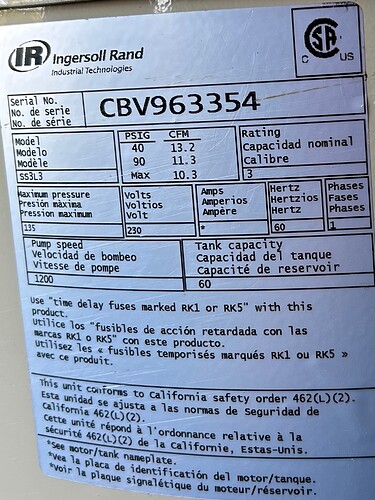
Here is the nameplate data for the SS3L3:
The flow is roughly double the requirement for the CFP and Razorweld 45.
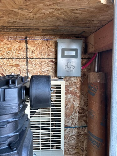
I have it installed at the front corner of my garage, directly across from the power panel at the other front corner. I ran a new 30A dedicated circuit for the compressor, and installed a disconnect switch on the wall above the top of the compressor:
Here is the view from the front outside of the garage:
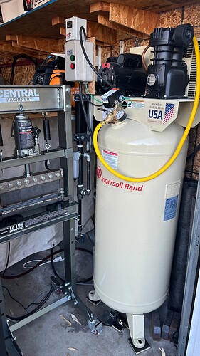
And another view from inside:
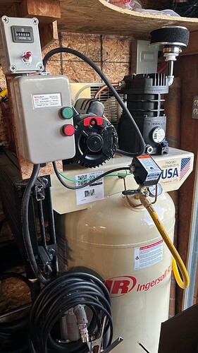
I added a motor starter, which takes the load completely away from the pressure switch. The pressure switch now provides the signal to the motor starter.
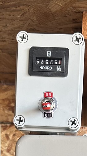
I added the 230V hour meter and switch in the small box on top of the motor starter:
The switch just opens the wire going over to the pressure switch. This allows me to turn it off, and the air compressor will not run. The disconnect I showed above is for if I want to completely cut power. The breaker is on the outside wall, and I can go over and turn off the breaker, but the disconnect is the most safe route to go if I am working on the wiring.
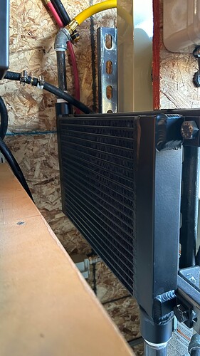
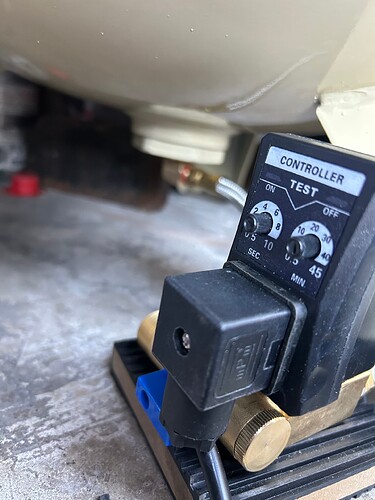
I do have an air cooler installed. I had originally intended (and actually reconfigured it) to have the air cooler be after the pump and before the tank; however, in the final configuration, I restored the original design, and the aftercooler is after the tank. Since I am a long-time Navy employee, everything must have an acronym, so I am in the aftercooler after the tank camp (AATC). There is a very long (~350 posts) on this topic of where to install the aftercooler. I am very much ok with the hot air going into the tank. I installed an auto discharge at the bottom of the tank to spit the water out periodically. I don’t want to re-start that argument here. I read through that entire string, and concluded I did not want any extra work on the pump.
The aftercooler has 1-inch NPT female fittings.
Here is the discharge from the aftercooler:
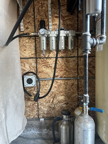
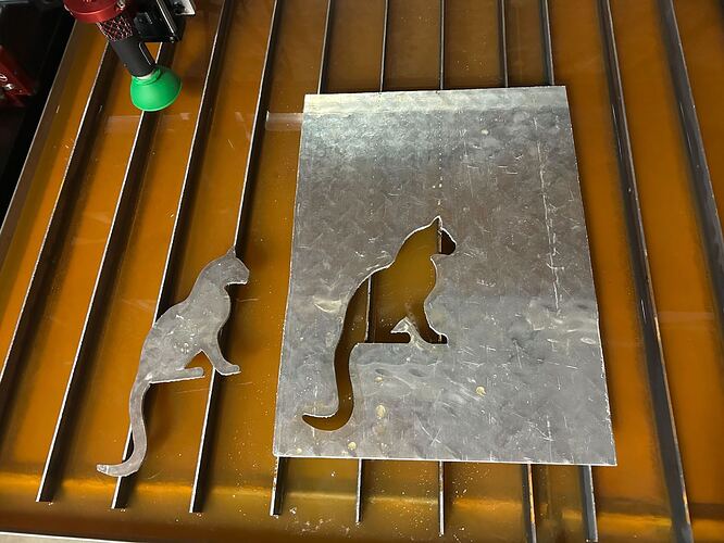
I can manually drain that line going straight down, and then there is the first air filter. It then flows to the wall to that 4 phase filter unit. I’ll try this initially and see how the air quality is. I have made no cuts on the table yet.
Down below the filter on the wall is the new 40A dedicated circuit for the plasma cutter.
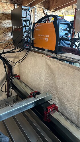
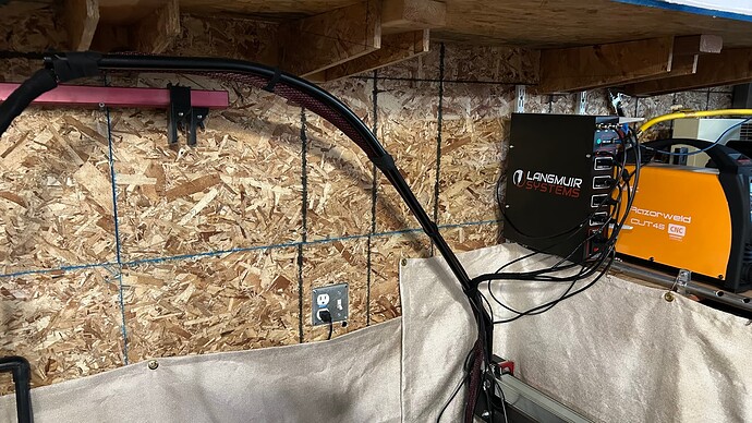
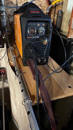
Next to the compressor and above the CFP, on the right side of the table, I installed the control box and plasma cutter. More on the CFP later.
