Creating this thread to document my build. I also posted on FB. Probably keep most of it here though. Crossfire Pro with THC, Razorweld 45 w machine torch.
Purchased late April, started late September unpacking boxes. I had to move my workshop from one garage to another, and also avoid Arizona summer, otherwise known as hell on earth.
I hate to break this to ya Jim, but I’m seeing other social networks. I didn’t want you to find out this way, but now that it is out I feel better. Do you? At least it was to the Langmuir support group on FB!
Take your time getting the table frame square and level, and make sure to check and re-check periodically.
This past week I took my table down to the black frame, as it had worked its way out of square… or never was square to begin with. I am leaning toward the latter as none of the holes lined up once I got to putting the water table back on. I am thinking that at some point it got knocked out of square before I installed the water table. I fought and fought to keep it square as I tightened the bolts. I got it close Friday night… then decided Saturday morning to try and get it closer… spent the whole day fighting it… finally got it square and tightened up. I installed the water table using marine adhesive with the original screws and new roofing screw washers per @toolboy (toolboy actually suggested pipe dope… I should have listened… grimacing:) After installing the water table, I checked square again… and it was back to where I started. I ended up pulling it square with a cable and turn buckle and re-installing the water table with new holes on one side. That finally did the trick… i wish I had just done that from the start. I have considered adding crossing cables under the water pan to keep it square. If it works its way out of square again, I think that is what I will do.
Good luck on the build… My best advice it to do everything in order and make sure you understand the next step before proceeding… I tried going off on my own and skipping around and ended up having to backtrack a bit.
I got the contract to do some seismic evaluations of some existing commercial buildings in the Pheonix area a couple months back… I told them it would be fall before I could do the work. Part of the inspection includes observing wall to roof connections… which means attic crawls. I don’t have to tell you when its 116 degrees outside attic temps can be unbearable. I had to do some a few years back in July… I started at 4am by noon I had to call it a day.
I was reminded this morning that I need to get down there and do the observations… checked the weather today… only 103 degrees. Guess I will be doing the early morning routine again.
I am going to build it OEM first. But if I decide I like it, I am thinking I’m going to weld the frame together, or build a welded frame.
I need to learn how to build a flat, square, parallel frame anyway because part of the reason I bought the CFP is to build a CNC router/mill machine from scratch. I also want to build some parts for a product idea for the Ford Raptor (I own one).
I have two ARCflat tables on the way… I can’t wait to get them. I’ve been using a cheap ¼" welding fixture table for a few years and I never quite trust its flatness. Its hard enough fighting twist from heat without translating the ground/concrete/table in to your work…
Definitely not suggesting you do anything other than follow the directions. Just reinforcing double checking everything stays square throughout assembly… you don’t want to have to do a tear down later.
Keep us updated on your progress and be sure to post some of your creations when you get cutting.
Not to over-think this cross-cable thing, but if there was constant tension inward would there not be concern of stressing the legs inward. Over time, this could result in some problems.
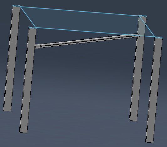
Solution/suggestion given to you as an engineer: would there be a device that was rigid that one could dial-in for the amount of sizing to maintain the inside dimension in this same diagonal orientation. I suppose it could be as simple as a treaded pipe with a coupler on one end that could be adjusted. Someone with a 3-D printer could fashion some ends for the pipe with a v-notch to locate on the inner edge of the legs.
Close-up of leg with 3D part that joins pipe to the leg.
Of course, this will get pretty busy underneath the water table: crisscross both diagonals with pipe and cable. A bit overwhelming!!! But nothing like bridge building.
Edit: Excuse my disorienting images of these sketches. I am just learning this stuff and right now these images are making me nauseated!
I am going to attack the problem by building a welded steel base similar to what others have posted here with at least two shelves for metal storage below the OEM legs, and bolted into the OEM legs. From there I will probably add a water storage tank underneath with a pump, and a set of drawers. It will be on wheels too.
Hoping that the steel frame base will act as a torsion box for the CFP and allow me to rack it to keep it square.
I think you are going to be just fine: the idea of creating the base is the secret sauce!
Please don’t read anything into what Eric and I are saying. I have not done any of these modifications to my table and I have not verified but I have not had any wonkie parts. I have wheels on the bottom of the legs and every time I use the table, I have to move it outside (about 60 feet each direction).
The Langmuir engineers are pretty confident of their product and have planned it to work as intended.
When people get into issues with the table, there have been some behaviors/modifications that Langmuir feel contribute to the table being out of square:
Never was square when completed initially
Wheels/caster added to allow for moving the table. This puts abnormal stresses on the table structure that was not planned.
Attaching shelves to the legs. Added weight on the shelves can also cause abnormal forces that will change the table alignment.
One over riding recommendation from Langmuir: (of course we all take this with the understanding: we assume the risks if we do not heed the advice).
If you need it to be mobile, create a mobile base which will support the table without tweaking the legs of the table with sudden jolts and change direction caused by bumps in the “road.”
That being said: could the current legs be beefed up and supported so they have the strength to handle those forces and still remain adequately plump and square. I think it could be done.
if we only had a plasma cutter, we could make some brace plates to add to all four directions on the legs.
I agree, not sure its necessary though it is pretty tight stock. The base will just allow me to create needed storage in my 2 car workshop, and move the table to driveway for cutting.
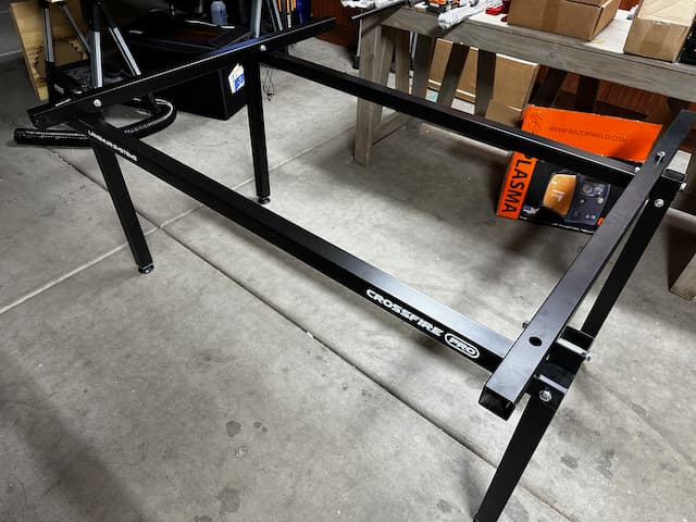
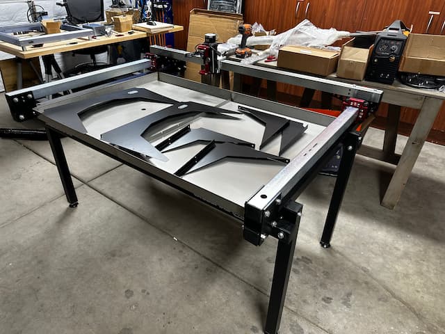
I was able to get this far this evening. Teaching this week so the long days are delightfully exhausting. The frame was 1/32", or slightly less out of parallel and 1/16" out of square so I squished it and moved on.
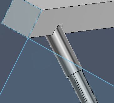
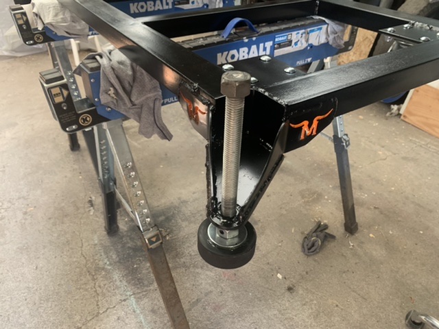
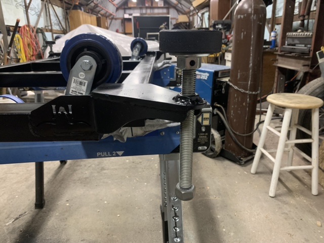
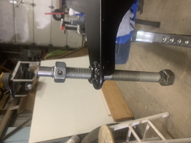
I just finished my rolling base a couple weeks back… I designed it over a year ago… I am pretty slow. I have almost the entire thing modeled in Fusion down to the washer on top of the hockey puck. I was going to cut a custom one so I could cover more of the top of the puck… but ended up just using one off the shelf. I did the modeling as an exercise to learn assemblies and joints for a future project. I did a short video on the leveling casters. I am planning on posting the components on Fireshare. I just wanted to make sure everything worked before I did. Here are a couple of pics.
I plan to take some more pics once I get the table back together.
Components List:
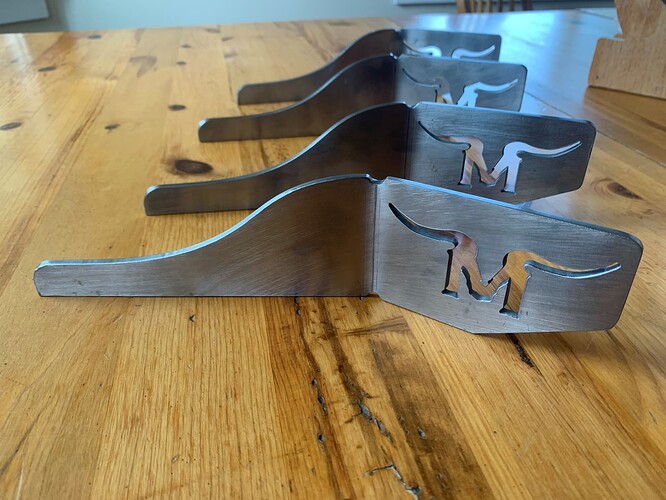
(4) Base plate
(4) 3-1/4” L3x3x3/16 angle
(4)Caster mount plate
(8)Gusset plates
(4) 9” 3/4” T rod
(12) 3/4” hex nut
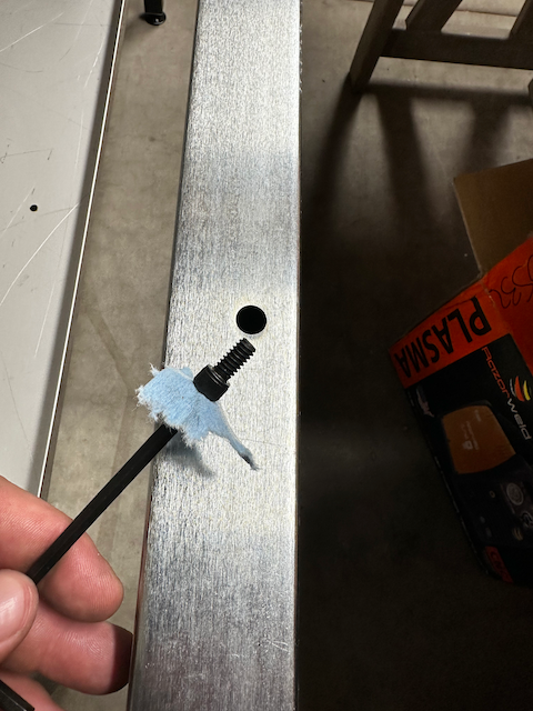
(4) 1/4 spring pins
(4) hockey pucks
(4) 3/4 flat washer
(4) 1/4x1-1/4 fender washer
(4) 1/4-20 x1/2” cap head screws
Frame Tubing… I used 14ga 3x2 and 2x2 tube because I have a bunch of rejected remnant from a local treadmill manufacturer… use whatever. If you want any dxfs of the cnc cut components, you are welcome to them.