I am having some issues with my setup Crossfire Pro with IHS annd Miller spectrum xtreme 625 and not exactly sure what changed. I can still make long cuts that look pretty good but small/intricate stuff looks like garbage. The changes I’ve made to the lead ins/outs seem to be ineffective. I am cutting 14 gauge steel with the follow settings:
-30 amp setting with 30 amp tip on xt-40 hand torch with machine shield
-200 ion
-110 psi with filter and drier
-cut height 0.059 and pierce height 0.157 (in fusion tool library setting)
-smoothing box checked at 0.0004 (tolerance set to same)
-lead-in radius 0.06, sweep angle 60 deg, distance 0 (my understanding is that in computer compensates)
-pierce clearance 0.055 (in 2D profile settings)
Post property settings:
Height 0.063
Spring back 0.02
IHS checked
Pierce delay 0.5
Pierce height 0.15
Retract height 1
As I am writing this I realize that the pierce clearance and delay are in both the tool library setting and in the 2D profile tab and in the G-code section. Not sure if inconsistencies across them could be an issue or which one has priority.
Last night I also noticed more of a yellowish look during some of the cuts and more smoke.
I have tried 40 amp tips and settings, varying speeds, varying air pressure. No real improvement.
If you are using the standard Post Processor for Fusion, most of the tool settings are not recognized by the Post. The values that are entered in the Post property settings are used.
That being said, I would set your pierce clearance to 0. (Pierce clearance adds its value to your lead in / out.) I would also reduce your Spring back to 0 or even -0.02. (Fusion adds an additional 0.02" for “backlash”.)
Feed Optimization (under Smoothing) can slow the torch when small details are being cut. I like to set it to ~60% of my feed rate.
I didn’t catch what cutting speed you’re using. For 14ga with 30A, Miller recommends 201 ipm. That may be a bit fast. I’d adjust that down and see if your cuts improve.
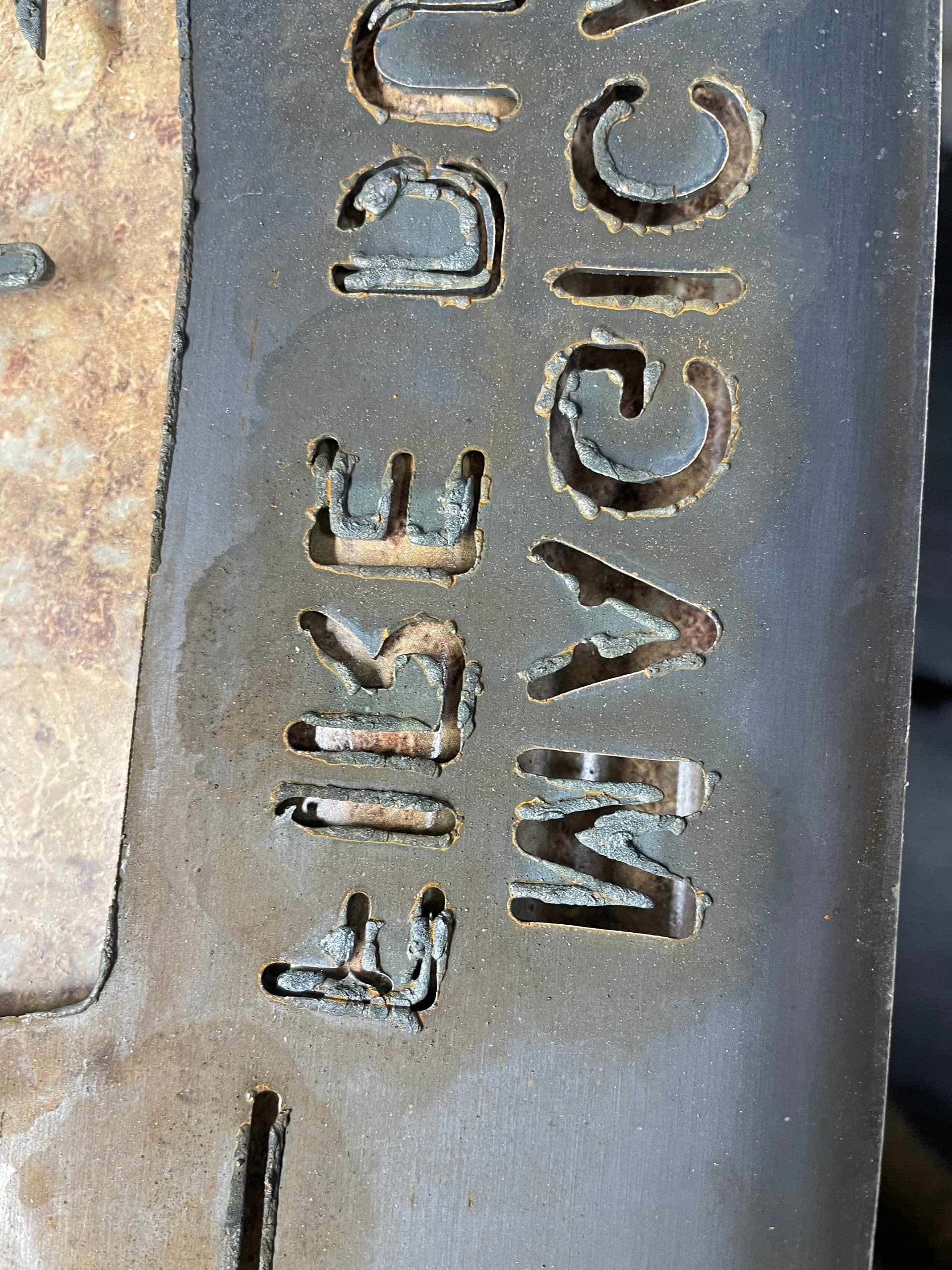
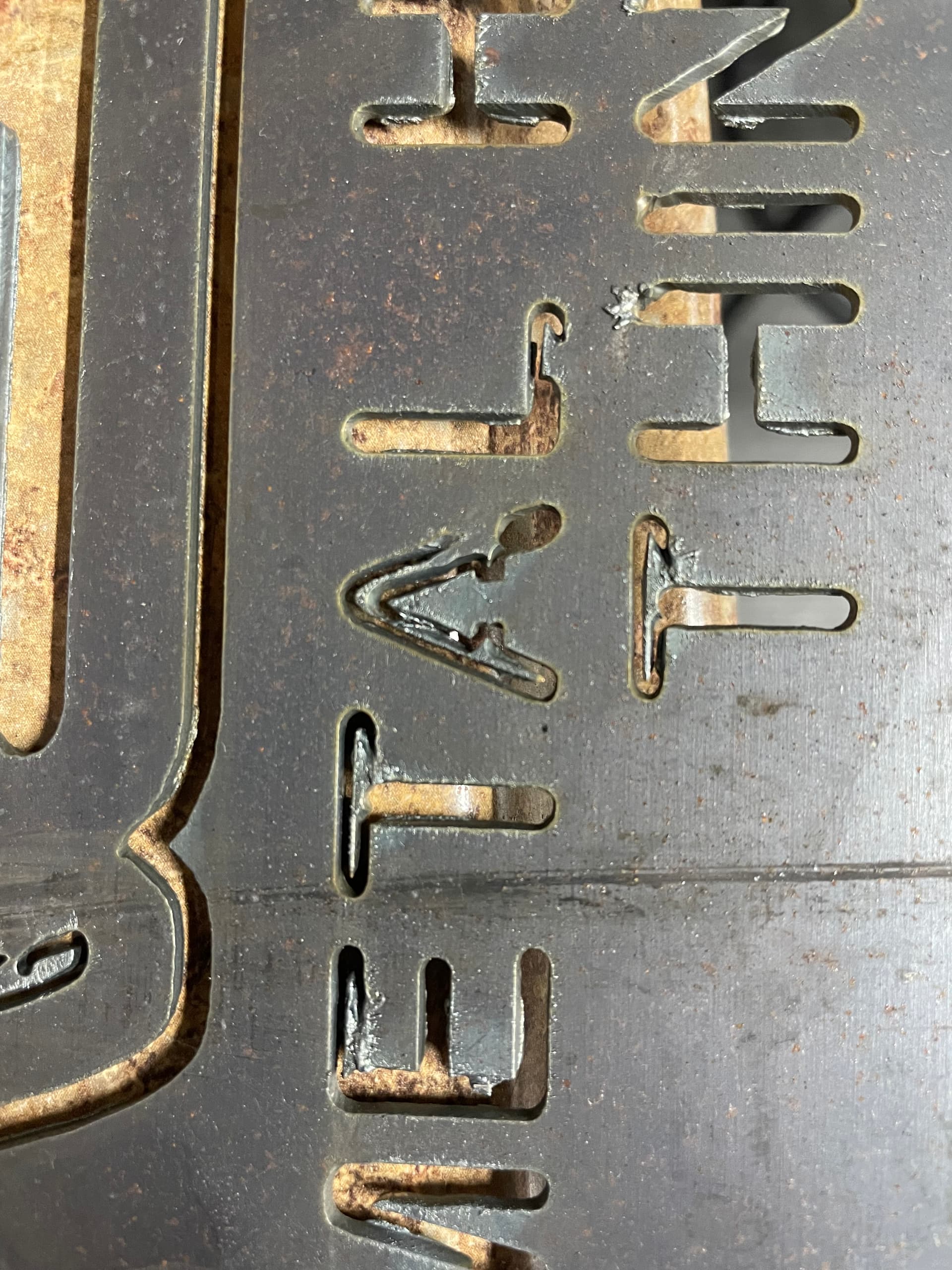
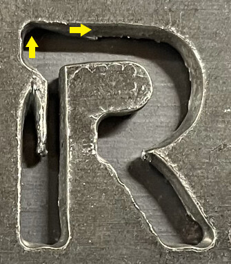
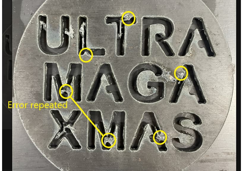
I posted the pics of the front an back of the piece I was talking about last night.
@TinWhisperer I misspoke, I am actually using the Deflector (249933). I do believe I have a machine shield that I could try though. Is there a benefit to one over the other?
You need to install the machine shield for cnc cutting. The drag shield is used for hand cutting only. When you install the machine shield set the cut height to .060, your cuts will improve and dam near dross free cuts.
Ok. I haven’t been using the drag shield. But the deflector “shield” I was using basically just has the tip completely exposed. Like shown on the diagram that was posted above.
I am not sure if this would be causing the issue, but take a look at the letters in the bottom pic. It’s like the lead in/out in some letters didn’t do anything.
160 ipm
40 amp tip w/ machine shield
110 psi
Cut height 0.05
Pierce height 0.12
Pierce delay 0.5 sec
Lead in/out radius 0.01, angle 60 deg, distance 0.06
Feed optimization toggled on at 80 ipm
Better, but still looks really rough.
I did notice a thin black layer of “soot” on the front side of the retaining cup under the shield when I was changing the shield. I wiped it out and blew out the holes. Not sure if this is normal or not.
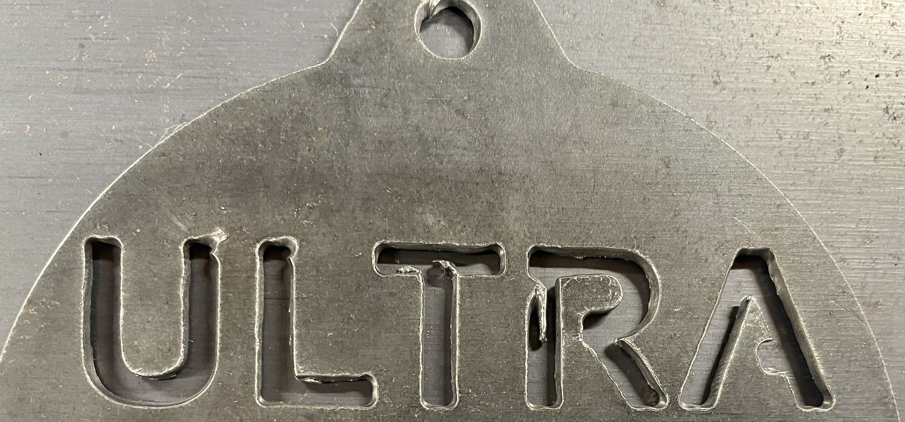
Let me know if this works. I’m trying to do it from my phone at work. I can export the file when I get home tonight if not. Thanks. It should show up as an ornament.
Let me know if the file works. I agree that it seem almost like the angles were opposite direction for the lead in/out, but I watched it in the simulation and it appeared correct. I appreciate everyone’s input and hope I can get it resolved soon.
I made a couple of changes. In design, I extruded your sketch. No issues there. In Manufacture, I redefined the setup and placed the origin at bottom left corner. In your tool path, I removed the chain selections, and selected the face. Changed Smoothing to .001. (My preference.) For you lead-in / out, I had to reduce in order to get the profile to cut.
@Simworx thank you for taking the time to adjust the file. I just got home and replaced the swirl ring, electrode, tip, and shield with brand new parts. I generated the g code and did not change any other settings. Here is how it looks without busting off any of the dross. Some areas look better but it still seems kinda funky on some of the lead outs.
I did measure it and it looks like the pierce and cut height are both what they are programmed at. Should the lead out height be the same as the cut height? It looks like it stays at the cut height until it comes all the way up to love to the next point.
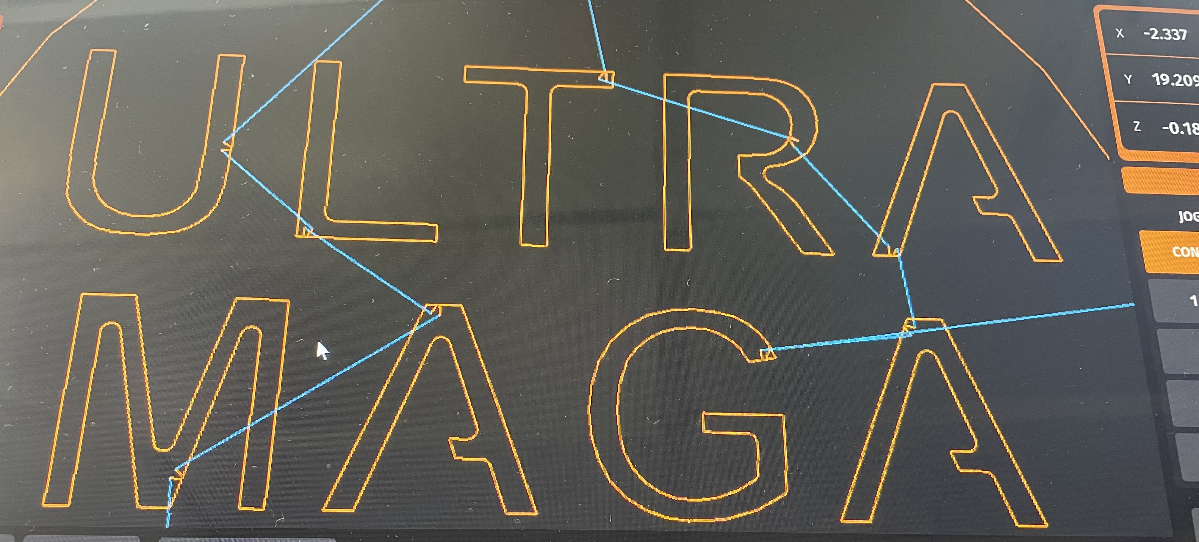
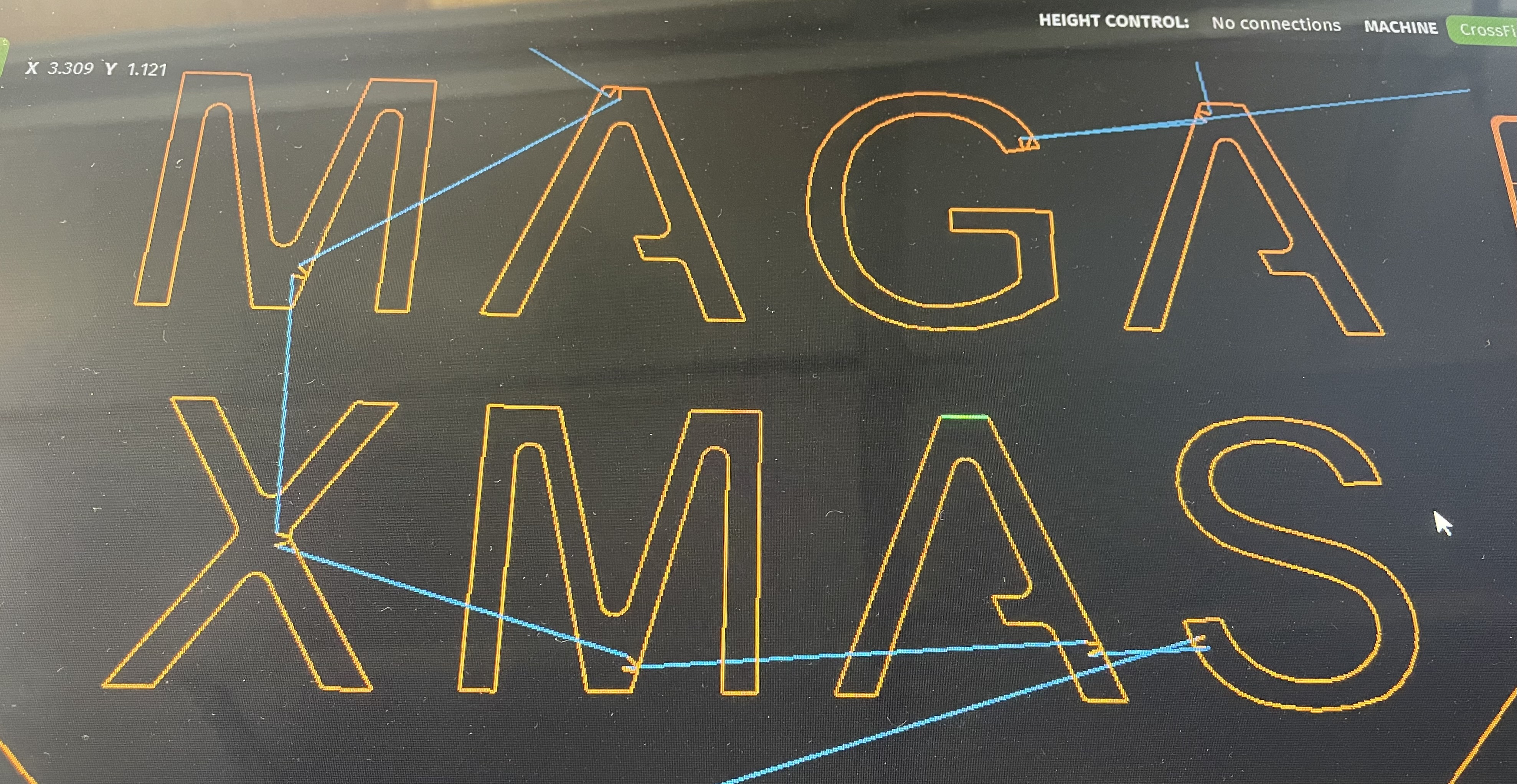
As for the problem areas you can see they match up pretty well with the lead ins/outs.
Definitely. The cut height should not change until it goes to its next “rapid” movement for the next contour.
That explains the "M"s and the "A"s.
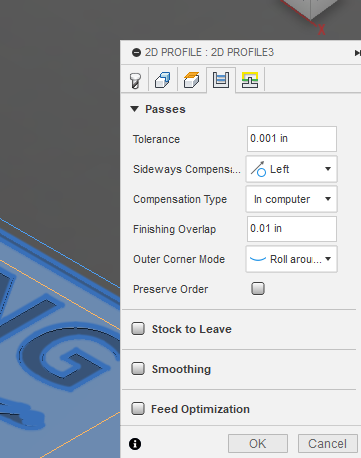
Try to CAM with a finishing overlap. In your case I would say 0.02 inches. That is in the fourth tab, fourth row down. That will force the torch to follow that area again, ever so briefly.
Edit: Looking back at your first post stating you have a “Pierce Clearance of 0.055 inches”. I would cut that to 0.0. It would be better to have more room for the actual lead-in/lead-out.