With work and kids, only been able to get 20-30 min at a time every day or so to work on things.
Last night I got out there and managed to get the vices on and trammed in. They are both within .0008" or less of tram, but they are slightly off set from each other by a few thou. Hopefully that doesn’t cause any issue with larger parts. Not really sure how long I should spend trying to get them perfect.
Tonight I hope to make a test part and see how things are. Ive seen that some people had to shim and dial in offsets, but havent really looked into whats involved there yet. Hopefully things are just good.
2 Likes
We also ordered the fully assembled version and will get receiving it soon!
How you jacked it up and off the pallet was exactly how I was thinking of doing it as well until I realized I could just rent a forklift pretty easily here 
Really looking forward to getting ours.
1 Like
A fork truck would be MUCH safer.
1 Like
Ran my first part last night. I need to slow down the default feed rate on the finish passes and up the RPM. I just let it do what SW put in and it needs adjustment. Things were between .000 to .005" out in places. Either way, was fun to try and make something.
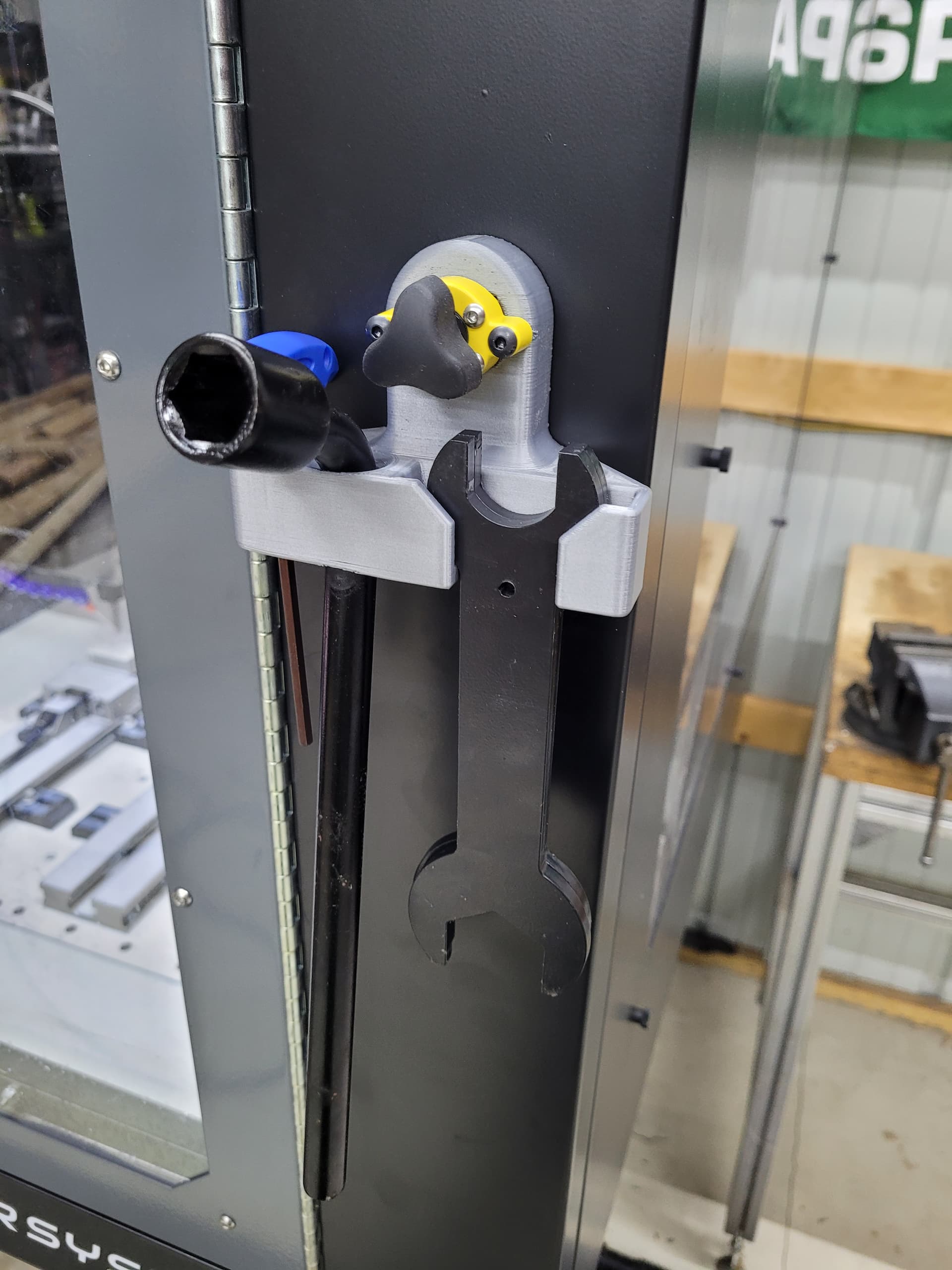
Also 3d printed a tool holder attached to a magswitch I have, so I can take them and mount them in the cabinet when Im working in there and outside when the machine is running. Seems like it will be more convenient.
4 Likes
How so? Note - I’m not being snarky/clever, I legitimately have no done a lot of heavy equipment moving (I used to work in a warehouse though where we drove around pallet jacks).
I was lifting a 1500 lb machine on two 8’ long 2x4s. It was pushing the limit of them and what they could hold for sure. Had one snapped, everything could have come down poorly.
2 Likes
Ohhh I thought you meant a fork “truck” was safer than a fork “lift” haha.
Yes, that sketchiness is exactly why we’ll be renting a forklift
1 Like
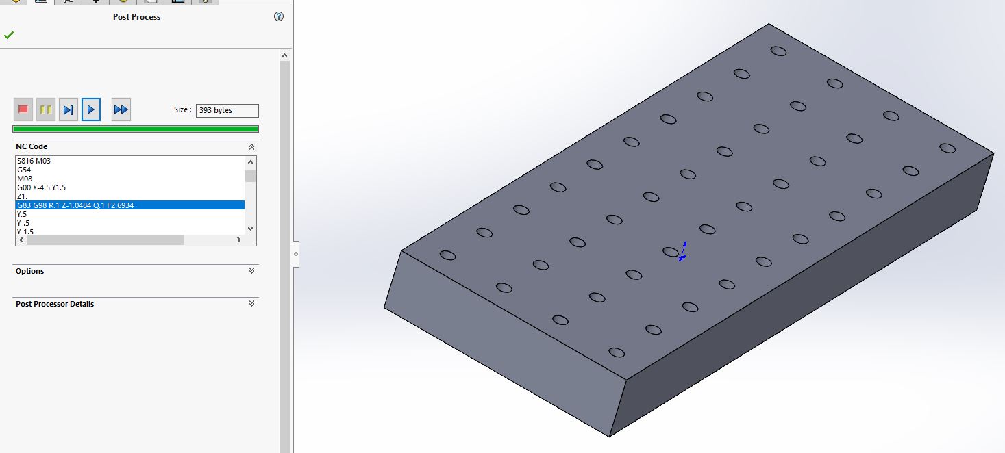
Come across a new issue, trying to build this plate with this bolt hole pattern in it. I cant get the code to run, it keeps giving me a check error on the highlighted line.
Doing some searching seems like there is no G8x in Langmiur post processer. Is there a way to get around this? Im new to using a SW CAM set up and I dont know how to tell it to post process differently.
Not sure if you have already done this, but you should download the post-processing file from the Langmuir download site and then you should import that into your solidworks. I am using Fusion 360 and in the post-processing window there is an option to import the file that I downloaded from the MR1 site. And that was it. Hope this help
Very neat! along with your two other prints. Would you be willing to post the three files here so we could also print those parts?
Im using the solidworks post processer
I posted the toe clamp storage here. I can post the other things later when I get a chance.
2 Likes
New issue. Trying to drill a tray of bolts last night. Finally figured out how to drill (Langmuir really needs to sort out the canned drill opp thing in their post processer). Doing the drill plate and each hole is 1" deep with doing .04" pecks per the Langmuir chart.
By the 4th hole, it was only 3/8" deep at the most, and I could hear an odd noise while it was going. Is something slipping? Im trying to find a picture of the spindle housing with the cover off, but havent come across it yet. It sounds like a weird tapping sound that I think isnt supposed to be there.
I at first assumed the collet wasnt tight and the bit was slipping, but I measured and thats not the case.
Any suggestions on what to look at here? I didnt have time to mess with it last night when it was happening, so Im hoping to get an idea of what to look for once I get a chance to go back out to it.
From the video it sounds like the Z stepper is missing steps. It’s really critical that for drilling (especially deep holes) that the tram error is as low as possible. Even small tram error can cause the side of the drill to rub against the hole being drilled which increases the required thrust.
My advice would be to move the spindle up in it’s mount, dial in the tram, and then see how it drills after that.
Other scenario could be a tight Z axis lead nut- which is unlikely considering we thrust force test all of these assemblies with a load cell before shipping.
What material are you drilling?
2 Likes
Thanks for the quick reply!
Material are grade 5 bolts. I thought about adjusting feed rates to even slower and lighter, but I havent had the time to check things out.
The mill was purchased fully assembled, so I havent messed with any of the tramming. I can take a look at it.
Ok makes sense- grade 5 should be around 30 HRC so will take a bit more drill thrust than run of the mill mild steel. What size drill bit?
What would you consider to be an acceptable range to avoid this issue?
Range as far material goes? It should drill up to 30 HRC as long as a good sharp drill bit is used and the tram is good. Considering OP is drilling 4x diameter holes, tram error becomes very important so i’d rule that out first.
1 Like
Sorry, I meant, what’s the range for tram calibration to be considered good enough?