I’m at the step in the assembly process where I am listening for the click on the two y1 and y2 limit switches against the limit switch stops and noticed an issue.
I got my y1 limit switch to click, then locked it in with the jam nut. No problem there.
On the y2 side, I’m finding that even with the limit switch stop maxed out forward, I never reach the limit switch position where it clicks because the tip of the limit switch stop is hitting the hard stop. The limit switches are oriented correctly in the right holes.
There is a sizeable difference between the hard stop and y axis carriage on one side vs the other. The video calls for bringing the x axis as far back as you can, to about 1/16". I’m there on the y1 side, but the y2 side is a much larger gap, so there could be something to that.
My consideration is to grind the y2 limit switch stop tip down so where it contacts the motor mount hard stop is shorter and would give room for the limit switch stop to be able to press on farther until it clicks.
Anyone had a similar issue or have advice to resolve?
It sounds like your gantry is racked and not square. You may have the square it (I do this by turning off the control box and turning the leadscrews manually). Getting it close is the first step in setting up the limit switches.
Both the stop screw and the “bumper” (for lack of a better term) that hits the limit switch are adjustable and have a pretty wide range of adjustability.
I was about to post with a similar question. I hadn’t noticed the gap until after i squared X to Y. So i can now jog an indicator across a 1-2-3 block with .0003" tenths travel along X axis- 3" side. But the limit switches werent aligning properly- I added the details below:
I was unable to install the limit switches aligned like the Assembly video. If I move them to other holes and flipped them, then I can still get the switches to trigger properly. Is this typical?
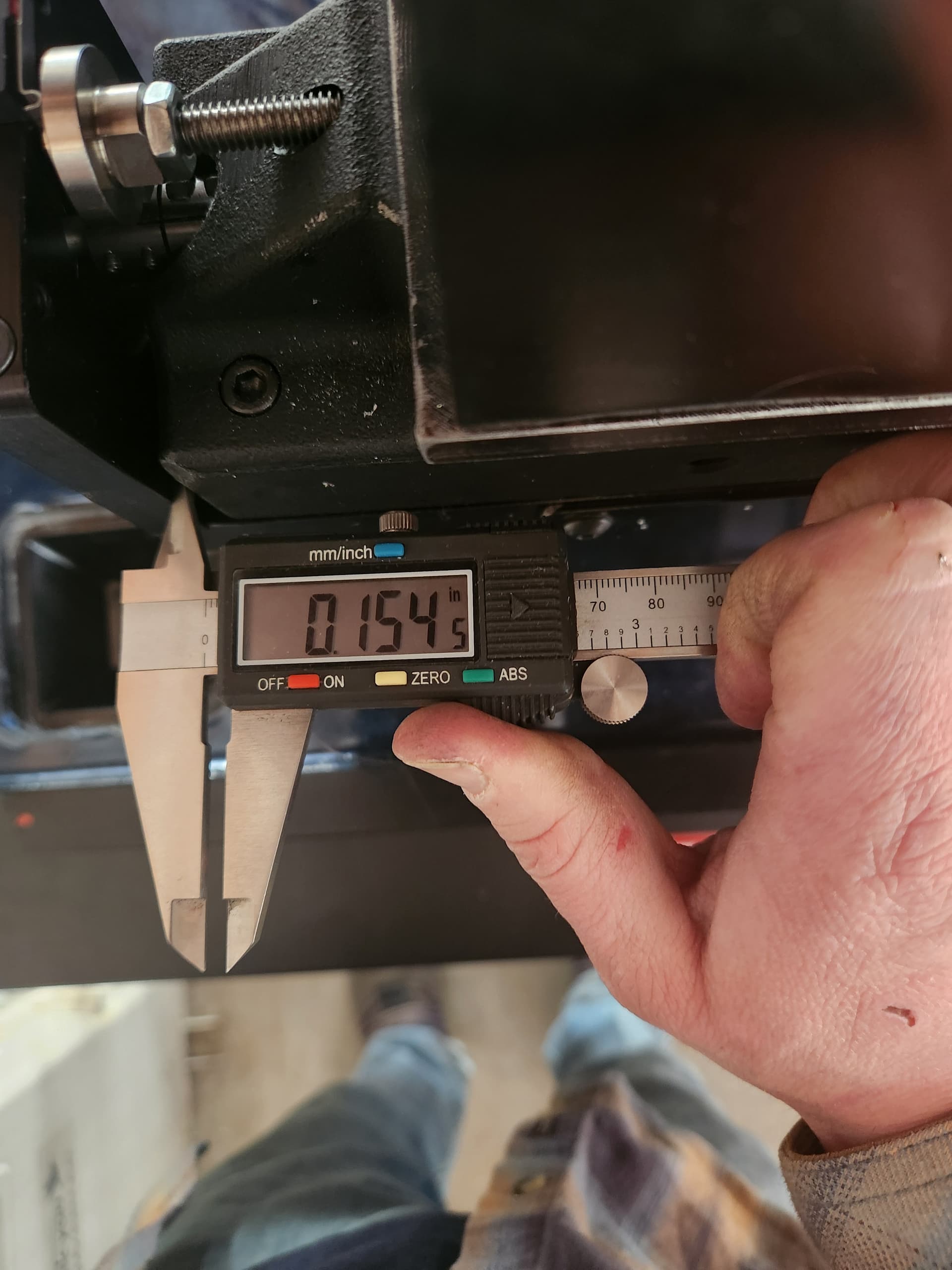
I have a .250" difference in space between the rear Y-axis hard stops. It looks like only about .160" or so of space between the front Y hard stop. I currently have the X and Y axis squared, and I can rapid in any direction and observe no odd sounds or steps. I know many assemblies can intentional gaps such as these, but would appreciate any feedback.
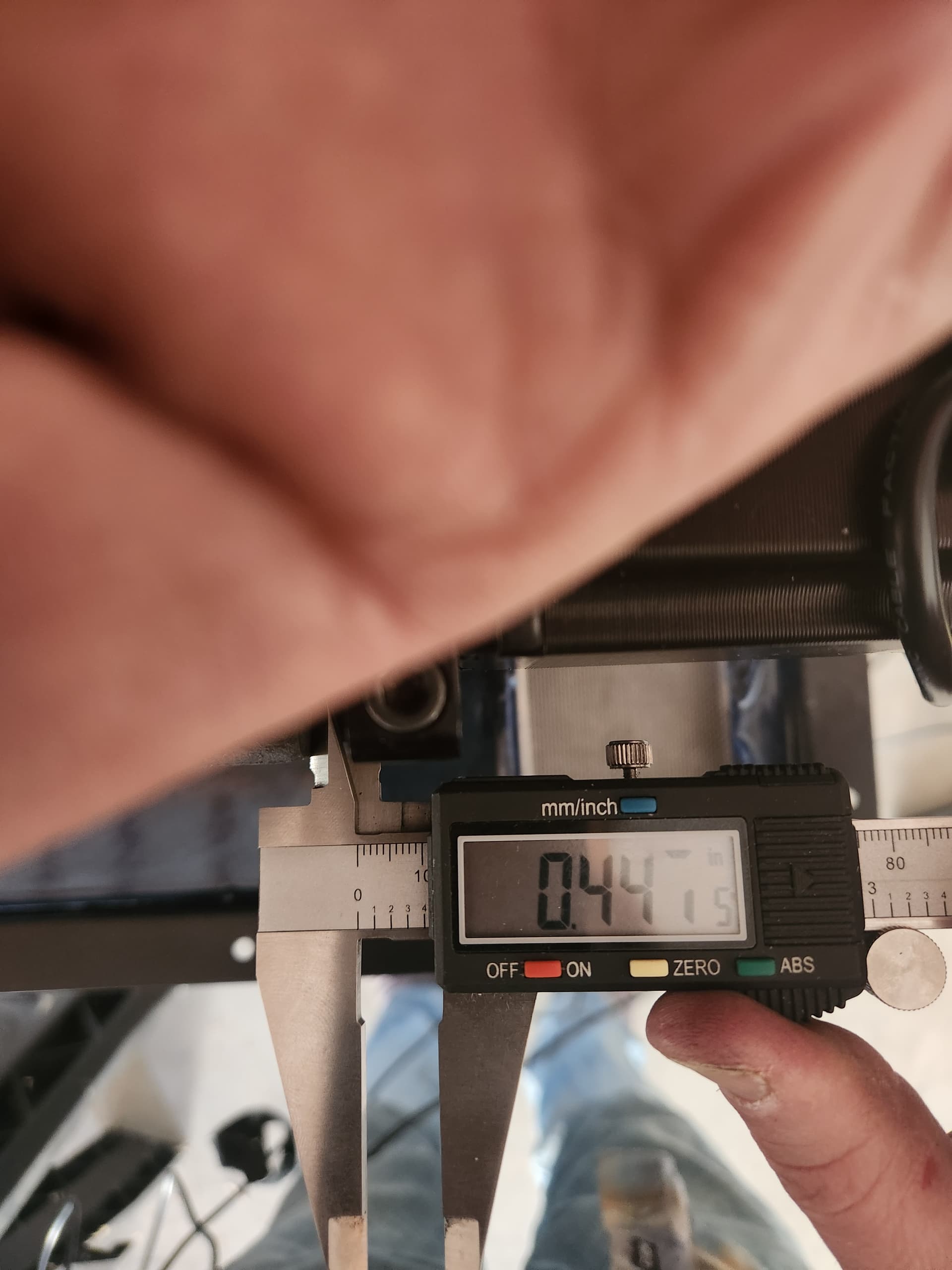
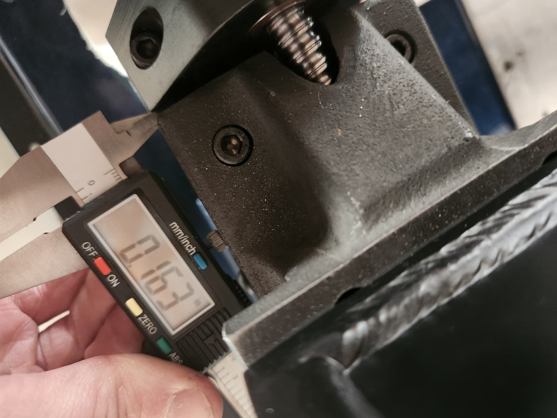
These pictures are the spacing between the hard stop and motor mount for the Y2 rail. .447" limit switch side and .163" on the front bearing side.
Get out the assembly instructions and follow the squaring of the gantry by loosening the indicated bolts and getting it squared up. Then follow the directions on how to adjust the ball screws on the Y-axis by turning off the power to the motors.
If the limit switch won’t mount up to the instructed holes something is assembled wrong. They only can go on one way and work correctly.
I will have to take more pictures in my case, but i went through all the instructions and squared the axes to my 1-2-3 block along y with bolts 6 bolts loosened, and followed all remaining instructions. Everything looks square on the indicator. It was only after establishing square, and went to mount the switches, that i noticed the gap between motor mount and hard stops were different by. 250" between y1 and y2. I can mount the limit switches with the holes provided, but not in the alignment or specific holes they call for.
For the guys who have assembled and operational machines- if you hit your hard stop on y1, is y2 at its hard stop as well? Should it be?
I feel like if the machine is indicating square as it travels, and y axis can rapid across the entire ballscrew without binding- maybe having to flip a limit switch over so it engages the tang properly isnt the end of the world?
Something is not correct. Post more pictures. Forget the limit switches for a second. If you manually bring the carriage all the way to the back. Do they both touch the Y ballscrew supports?
Apologies, it will take a few days for me to get back out for better pictures. The caliper pictures there are the measurement from the back of the y1 and y2 carraiges to the hard stop/motor mount.
So to snswer your question: No only y1 will touch the hard stop, and y2 will be about. 25 away from its hard stop.
Let me know if there is a specific angle youre looking for.
Follow the instructions on squaring the gantry. Loosen the bolts they tell you too and swing that gantry so it touches both supports. Forget the 1,2 3 block for now. Thighten up the bolts and move on to the next chapter in the instructions.
I agree more and better picture will help. The top pick your hand is covert what actually needs to be seen. The bottom picture looks to be you measuring the front bearing block?
First bit to make sure. The gantry should not be hitting hard stops. When moving to the back of the machine the limit switch should be set to trigger before the gantry hits the hard stops. For moving forward you will set a soft limit in cut control that will allow the gantry to move a present distance from the limit stop at the back to the front. You will set that just short of hitting the hard stop.
I do understand that i dont want the hard stops to hit once i set the limit switches. I can take whatever pictures are best to look for other issues if requested.
I dont understand, because i did all this- and it does run square to block…this is the exact video I followed.
Unless you are telling me to hand screw the ball screw on y2 until they both touch touch the hard stop, and then try to square it- but that doesnt make much sense to me.
If its running square along X and Y now, what is there to adjust or redo?
I just mean what else can I redo from this video alone? All due respect, i appreciate all feedback. I will try to find more measurements relative to this issue and provide more clarity maybe.
Im not sure what the rules or limits on the forum, as far as video posting. I have video of the machine rapiding along x and y and sounds comparable to others posts Ive seen. How far off square can the machine be before experiencing missed steps or something? I don’t percieve any on the indicator along X or Y or by sound.
I know you have a lot of experience looking over this forum, so i really appreciate your patience. Let me know how far off you think it could be before rapids would have an issue. I can post video on a facebook forum or something?
I’m pretty sure I figured out why I had the original issue which I originally posted about. I believe it is a direct consequence of an earlier struggle I had with getting the diagonals perfectly square on the y axis rails before the concrete pour. I minimized the difference between the corner to corner distances but still had 3/16" from one diagonal to the other. This manifested itself to cause one limit switch to be able to activate and the other to not.
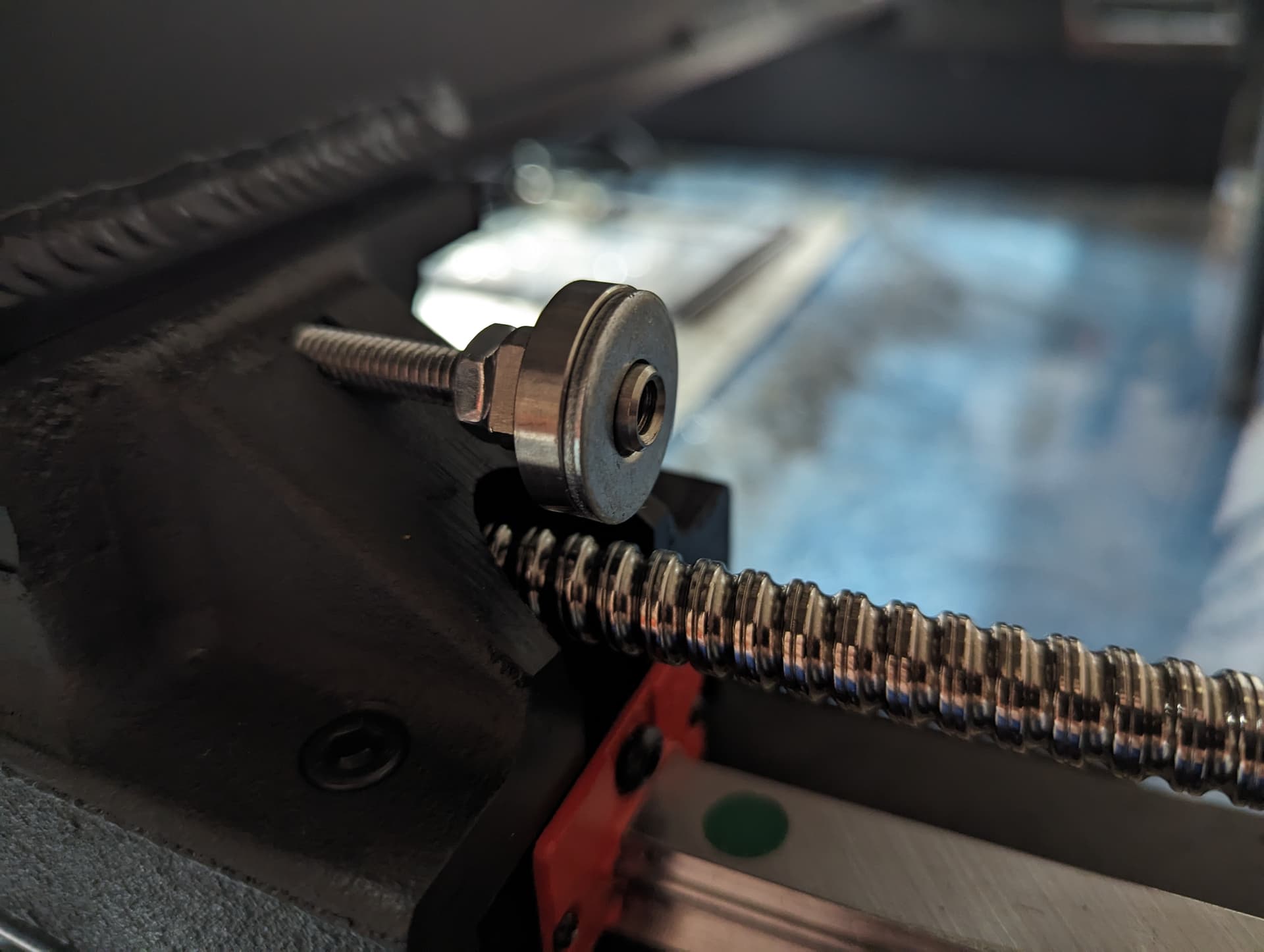
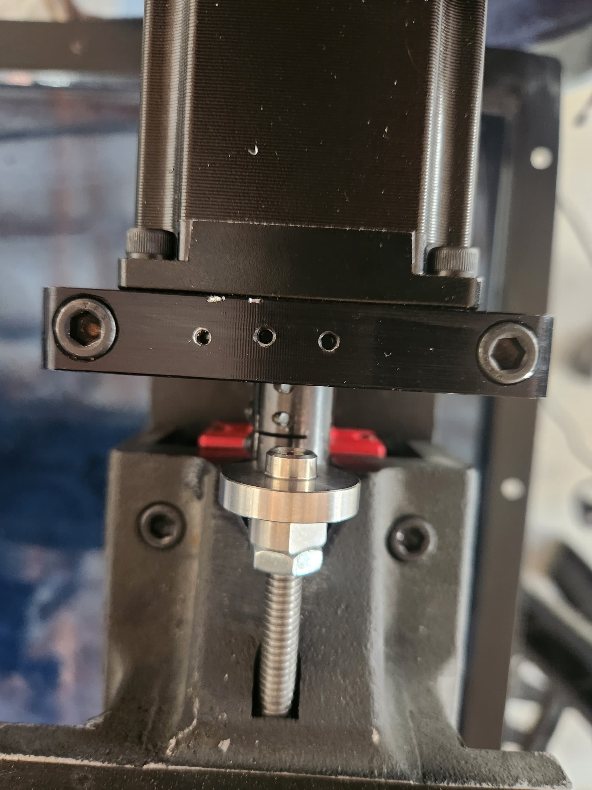
My work around which proved successful was to add a washer to the front of the “bumper”. This added just enough length to the bumper to allow that section to hit the limit switch trigger before the tip of the bumper hit the rear hard stop.
All the other steps in the video were followed to a T. The rails are square against the 123 block. Photo attached of the washer on the bumper which helped me get to the point of hearing both clicks at the same time
This is based on the two diagonals measurement that you do for the Y rails before pouring concrete. If I remember the build sequence properly they allow for some amount of error here, which is what you could be seeing. The squareness of the gantry is what matters, not exactly where the home position is on each of the Y lead screws. My guess is that your build has one of the Y rails starting slightly farther back than the other.
Adjust the hard stops so that the carriage hits them before the limit switch is out of travel. The hard stop is to protect the limit switch.
I appreciate your feedback on the machine squareness. I originally wasnt auper concerned by this possible difference. All my measurements through the build seemed pretty low.
I still plan to go over the machine and measure what i can to identify any previously unknown issue.
So assuming the rails are square, here is a picture of the y2 limit switch mounting holes- do they look properly aligned to you guys?
This is the worse looking of the two Y mounts. Are they supposed to be centered along X? It almost looks like it i flipped them over (where the motor mounts to opposite side) may end up aligning the switch per their layout. Any input is much appreciated!
The motor mounts are directional, if you review the build instructions you can see them mention this when you install them. So it’s possible that you have one or both installed backwards.
Those 3 small holes should be in a line though. Maybe they just show up poorly in that photo.