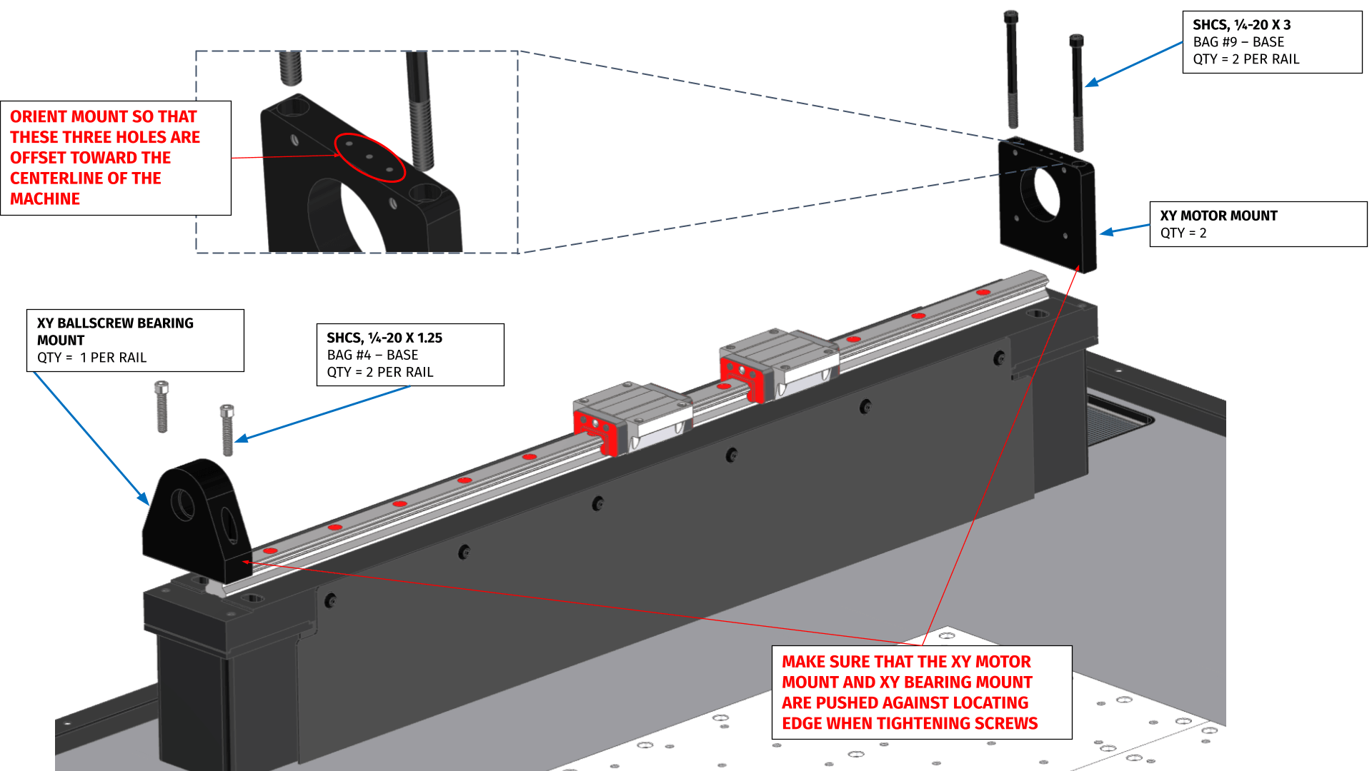
So they only reference I see is this picture mentioning orienting so the 3 holes are toward centerline of machine. If these are centered in the along “Y” then I do have the Y2 and Y1 mounts installed with holes toward center.
They way your switches are mounted in the bottom picture is correct. The arm should be inline with the center of the screw stud. I don’t however, see how your two Y carriages can be out of parallel by more than a mm unless you’re setting them up wrong.
The most accurate way I’ve found to set the Y2 switch to match the Y1 switch is to jog the Y axis in incremental mode in lower and lower increments between Y2 stop adjustments until they either switch simultaneously or within 0.0005" of each other (on the display, don’t rely on listening to the click).
The easiest way I think we, on the forum, can help you would be if you could record the process as you follow the instruction video above and maybe post to YT or something? If you literally did everything as shown in the assembly video SOMETHING isn’t right with your setup/build. Identifying what is the issue.
Ok guys, took a minute to try and edit something basic together. This link should have a video of laying out some basic measurements and details and running along 1-2-3 block.
Im also going to try to get through to support and seen if they have an opinion. I dont care if there is a small gap as long as the machine functions well. Love to be sure though!
I’m not seeing any issue here. The differences I see in your video aren’t concerning to be honest. The Y carriages are cast parts so there’s going to be some differences, so long as the rail mount holes are able to attach to the rail bearings without twisting or preloading it doesn’t much matter.
If you set your 123 blocks square to Y and then only adjusted Y2 ballscrew to square up X so its perpendicular then set both Y switches to maintain that squareness, that’s exactly what you should have, regardless of any gaps, if the X and Y are perpendicular, you’re good.
Hey @Dre, thanks for your feedback! I finished wiring the limit switch stops, and everything seems to be functioning as it should. I did notice my overall travel was about .120 or so shorter than their example in the video. So that was discouraging, but hopefully wont feel like i need that .100 so bad. @Bigdaddy2166, did you have time to look at the video above and let me know what you think?
Also, has anyone had trouble sending a support ticket from an android phone? I only get a 500 server error.
I plan to call tomorrow and see if i can get through, or dust off the laptop.