Thank you for this, I’ll check it out more later. I do notice it doesn’t have 24 or 28 tpi but anything diameter wise should be around the same. A lot of gun industry stuff uses 1/2x28 and 5/8x24 so that’s what id primarily use.
You can add any thread standards that you want to the table. I just have it populated with the ones that I use.
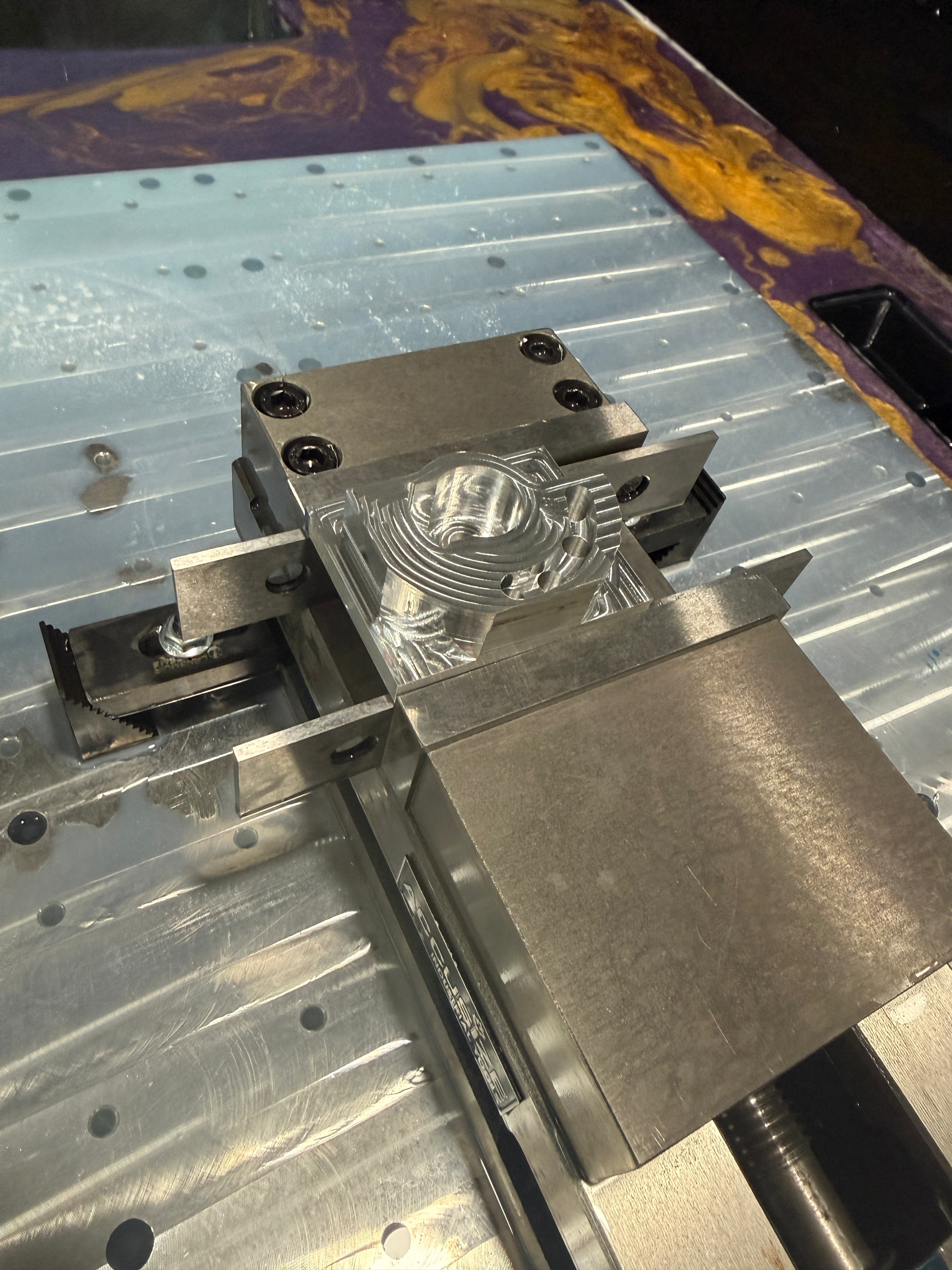
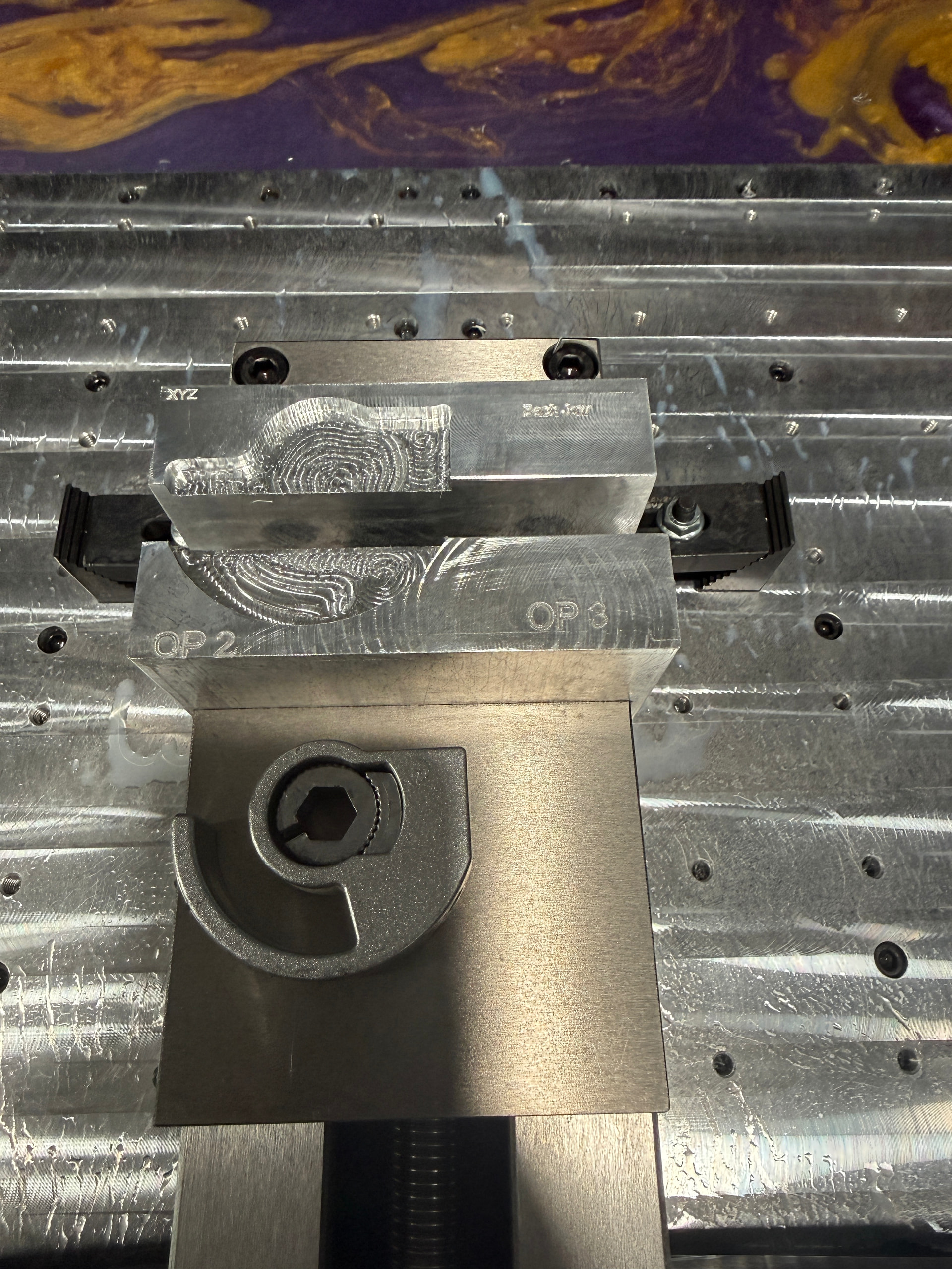
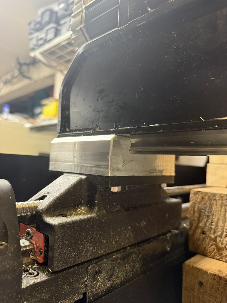
I Cut my stock to short by mistake on this part but the next one will be right lol. The last picture the part is sitting on the vice is what im making but stronger and more reliable. Its for my friends drum pedals. The other one snapped on his and he can’t buy the parts anymore. Don’t mind the jacked up soft jaws I wasn’t taking my time designing them so the letters are off but it works that’s what im looking for.
3 Likes
I made some 1.5” high riser blocks using MIC6 aluminum. I picked this material because it’s ground flat and accurately and also because cast aluminum has good vibration dampening properties.
The riser blocks are installed in the gantry using 2.5” 1/4-20 set screws which are installed as studs into the gantry. The blocks are then placed over the studs, and secured with nuts from below. This is much easier than trying to get really long screws mounted up through the bottom.
The blocks aren’t beautiful, but they are functional. Everything is slathered in grease to keep galvanic corrosion at bay.
The extra 1.5” of clearance provides more room for putting a tool changing rack for automatic tool changing at the back or side of the machine, instead of in front where I had it before. My spindle uses ISO30 tool holders, and now I can fit a 3” tool with clearance for the gantry. 1” would probably have been enough, and would have been a lot easier to machine (it turns out that I don’t really have endmills with 1.5” tall cutting lengths).
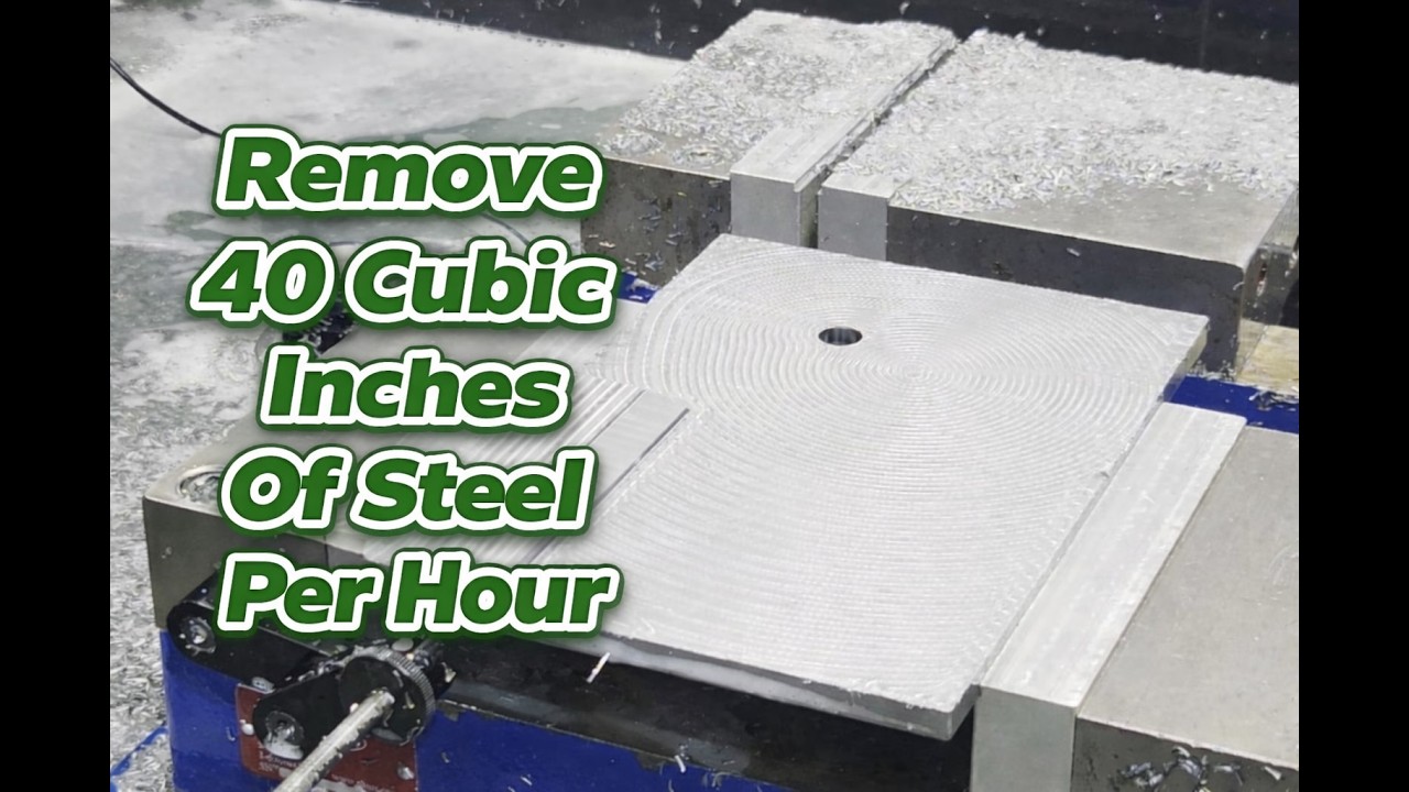
I did my first test cuts yesterday with the additional height and am happy with the results. I tend to run the machine a little more lightly (vs maximizing material removal rate).
6 Likes
I need to make me a set of those spacers for sure. They are on the list for when I get everything else done.
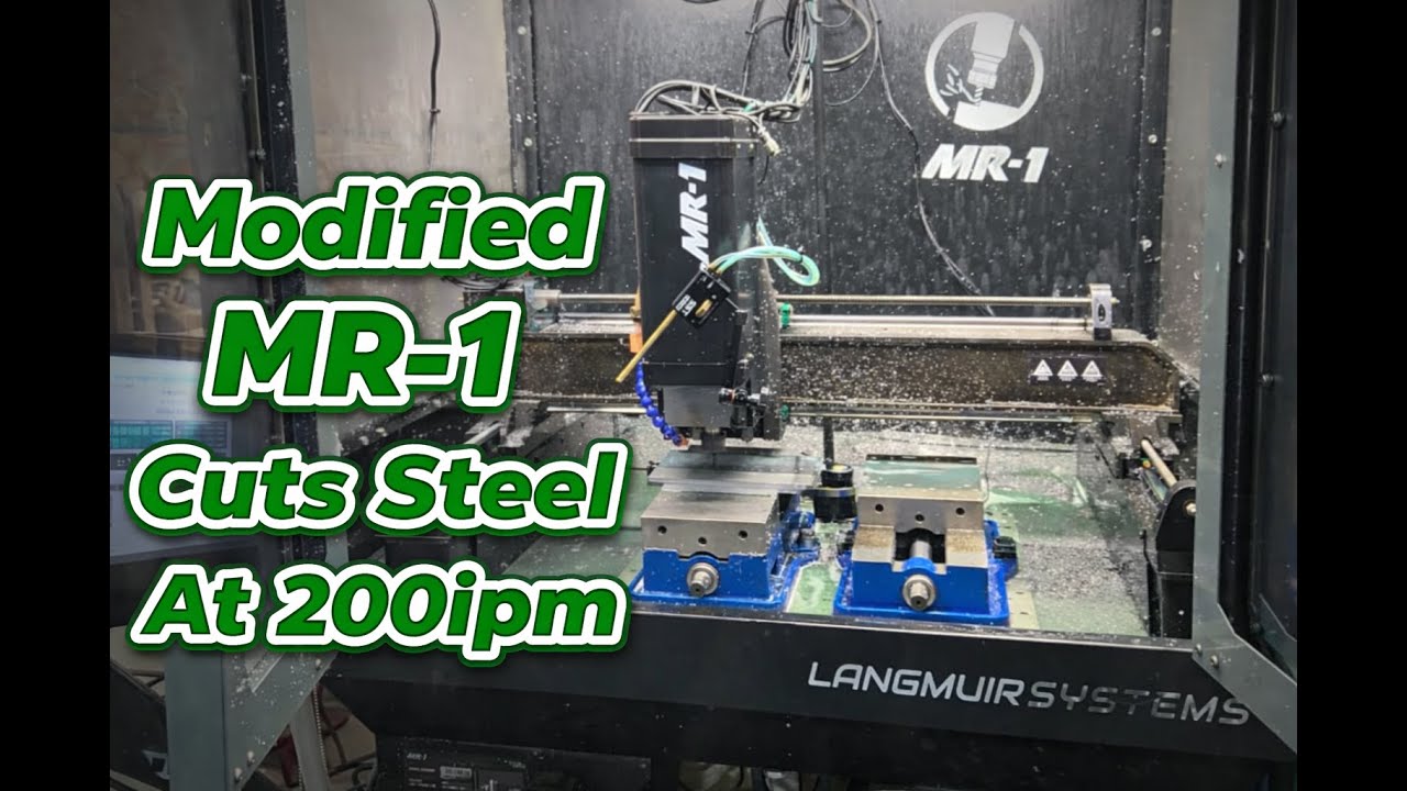
Here is what I did tonight. Machining some 4140PH on the MR-1
4 Likes
Why not steel?
Cost, damping, weight were why I picked cast/ground aluminum instead of steel. I used Gleich C250, but have used MIC6 for applications like this in the past.
I admit that steel was what I originally thought I’d use, but then someone suggested that I look at damping properties of cast aluminum.
I bought this as a cutoff on eBay, it was $80 for enough material to make 4 riser blocks. The extra material will come in useful for other projects.
1 Like
Hey Alex, do you have the bolt pattern dimensions for those risers? I havent gotten around to making mine yet, but it would be nice to rough it in in the machine and only take this thing apart once.
1 Like
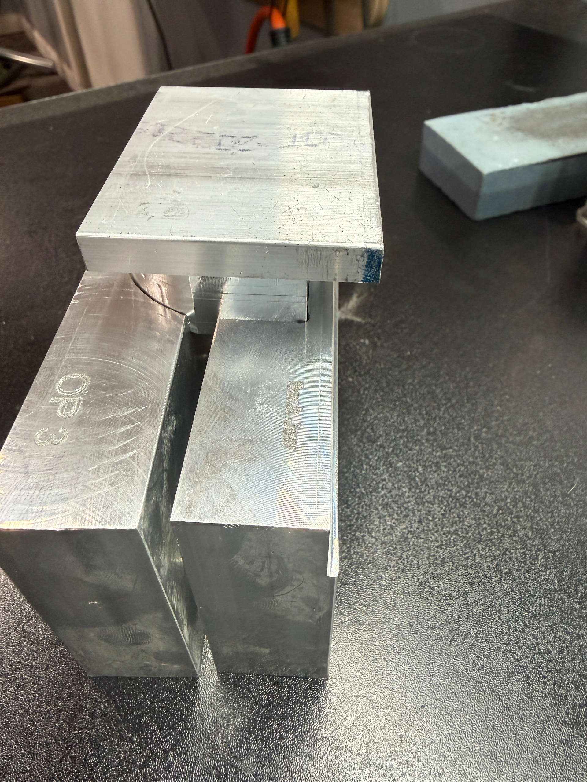
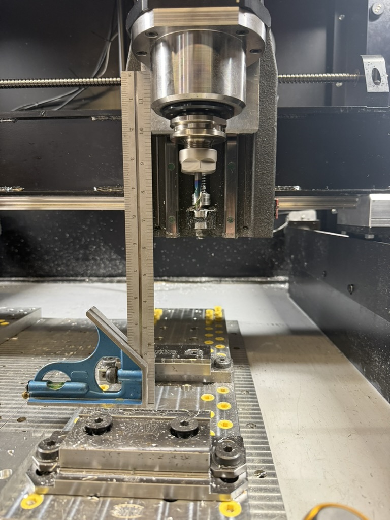
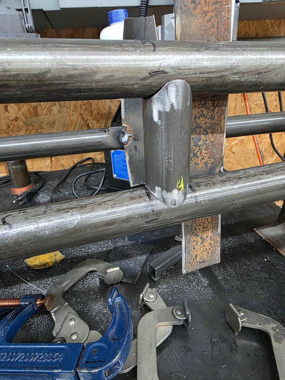
First operation on the new knife fixture. Since this one might be a high runner I decided to make it out of steel. (and I’m out of aluminum hahaha)
4 Likes
Richard, is there somewhere you have detailed or listed all the modifications you have made and the hardware you have used to upgrade your MR-1? I would like to do the same but am not sure where to start.
There is one that has been posted here multiple times by @amosdudley . I just used a minor variation on his design.
This is the thread were I learned about modifying the firmware. all that info is in there
Anyone try UGS? - MR-1 - Langmuir Systems Forum
I used factory high power drives and these motors
NEMA23 570oz/in 5A 1/4” Dual Shaft Stepper Motor (KL23H2100-50-4BMC) with Cable |
You have to turn the factory drives up but then you’ll need a larger PSU. Once you up the volts on that you’ll need a new 36v psu to power the control board. You’ll also need thicker wire from the dries to the motors connection panel. You’ll need to learn up on all these things. There are too many variables for me to teach you. Took me months of research and learning. If you don’t fully understand you’ll destroy your machine. You don’t just bolt on a couple parts. You completely rewire your control box and mod your firmware and replace all your motors and limit switches.
I used this PSU https://amzn.to/4tqAVQD for the drives
I used this one to power the control board LS35-12 TDK-Lambda | Power Supplies - External/Internal (Off-Board) | DigiKey
I used these limit switches Precision Touch Limit Switch: 8mm diameter, 3.5mm plunger (PN# CSK087B-L) | AutomationDirect
If I were to do it all over I would go with new closed loop drives and motors.
Richard, thanks so much for the information. Sounds like a bit of a challenge, but I have never been one to back away from the difficult, so down the rabbit hole I go!
2 Likes
Heck yeah man! The MR-1 frame can handle way more than the factory electronics. Langmuir tuned it to last forever, and make it forgiving for new CNC users.
1 Like
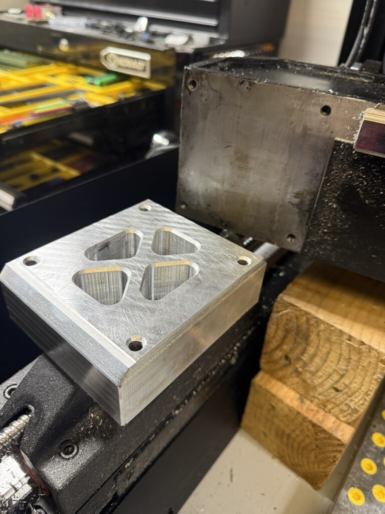
Making a steel fixture on the MR-1. The first try was way too aggressive. I didn’t feel like breaking another endmill so I cut the stepover in half and tried again.
2 Likes
What’s your spindle rpm when you cut that fast?
7500 rpms since it is mild steel I could have gone 8,000 with this endmill. The finishing pass I’m moving at 200ipm.
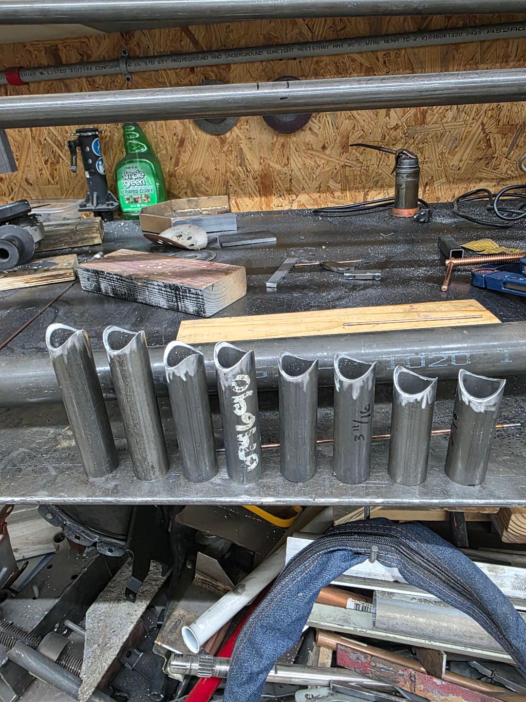
Did you cut those with a hole saw, or with a tall endmill that could get to both sides?
I thought about doing this on the MR1, but made tools to do tube nothing on my lathe instead (tubing clamped in the toolpost, holesaw in the spindle).
That’s thick tubing! I do this for bicycle frames, so it’s usually 0.035” (4130 steel or hardened forms) or thinner. Occasionally I do stuff in 0.058”.
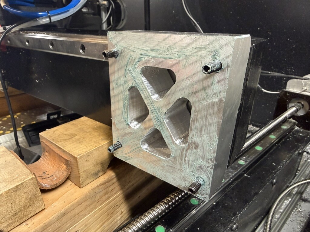
I used a 1/2 inch end mill with a boring tool path and 3D printed soft jaws to hold the tubing in the vise. Those notches were cut at 87.5 degrees with the bottom yet to be cut at 90 degrees. The tubing is 1 inch DOM with .093 wall.
1 Like