After taking delivery in September and spending an inordinate amount of time on the assembly and adding “extras” that were discussed on these forums, the machine is now running and alive.
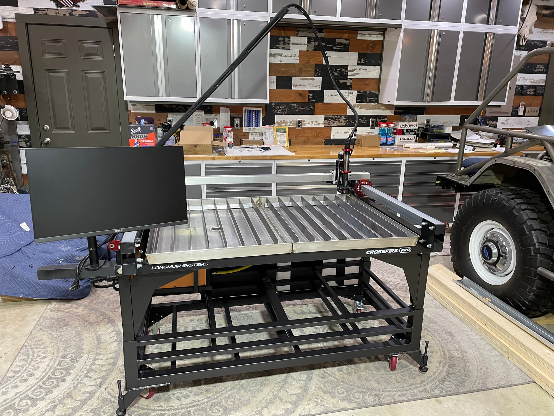
Here is the high-level view of the machine. Built a nice rigid rolling base with storage for sheetmetal underneath, and levelers at each corner to combat the angled concrete garage floor.
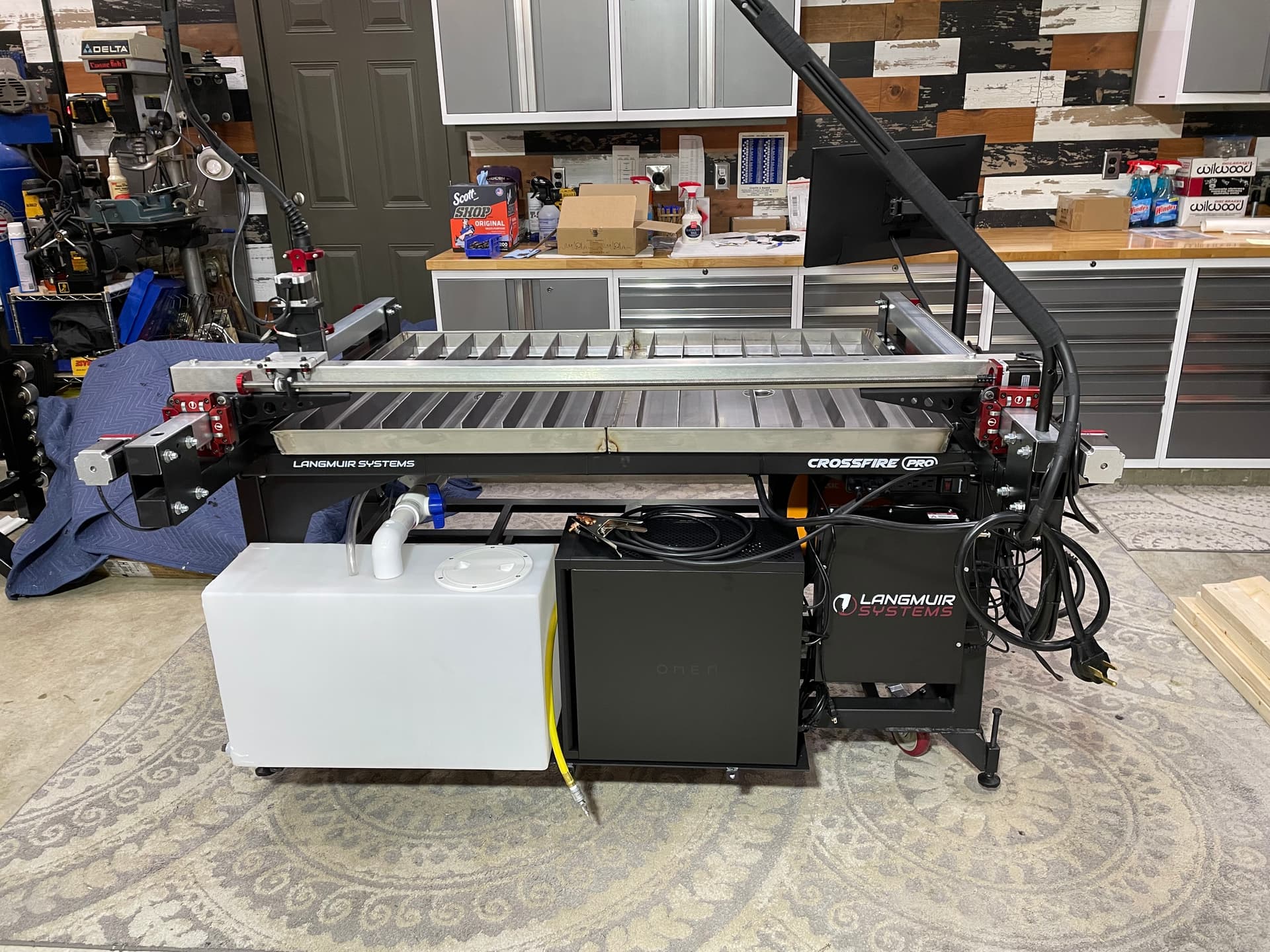
Installed the control box off the back next to a new HP gaming PC, and a 16-gallon RV tank with submersible pump that fills the water table up through the drains
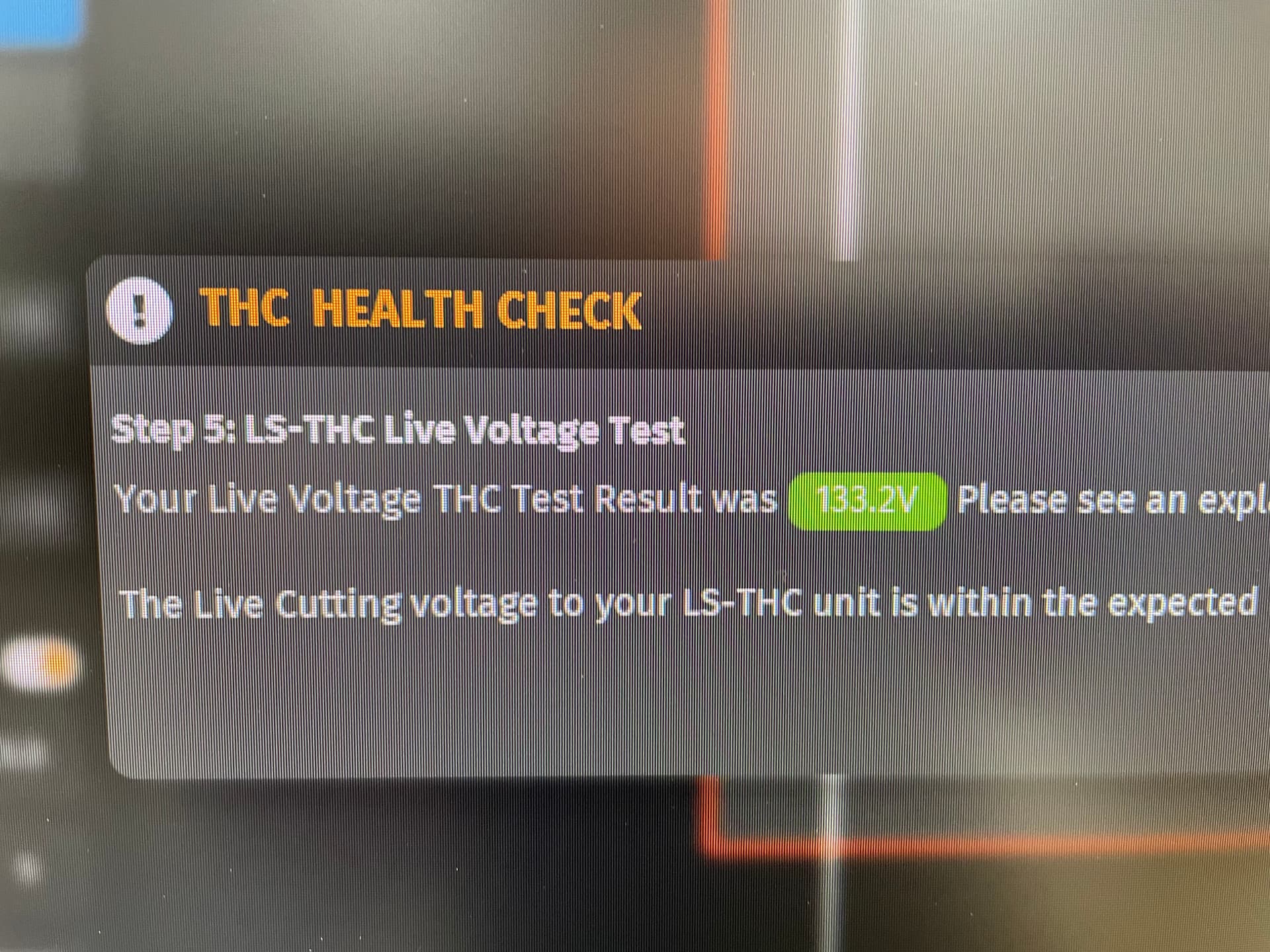
As some of you probably saw, I also installed the new Langmuir Limit Switch Kit and had a small issue with one of the Y-Axis motors, but the tech guys were awesome and got me the new part in a hurry. After that, the hard and soft limits were set and the machine seemed to be moving fine. All that was left was checking the functionality of the THC on the Z-axis and to test fire the plasma cutter to see if it actually worked… The calibration seemed to go fine and I got around 133V on the torch.
So the next step was to throw a thin sheet of steel on the table and do a few manual 1" cut tests to confirm that all of my efforts were going to pay off…
It worked great!!! I had the plasma cutter running around 90psi and 45A initially… turned it down to around 30A just to see if that made any difference…
GREAT! So now I have what appears to be a working machine… but there seems to be a little confusion about what to do next…???
Based on some of the forum comments I’ve seen so far, these are some ideas that should probably be done next:
3-in-1 Oil on all the leadscrews and bearings before any real cutting begins
Make some calibration cuts to determine if the table is cutting accurately, and if parts are “square” when they are supposed to be. There are probably cut files out there for all of this…?
Figure out settings for plasma cutter. How many amps / psi for each type of metal used. I saw a RazorWeld Cut Chart thread, so I will use that as a starting point.
Figure out the finer details like pierce delay, travel speed, and other attributes that will insure that cuts are clean… and minimize any unwanted angle in the cuts themselves.
Crawl before Walking: Start playing around with Fusion360 and FireControl to do very simple programs and understand how to properly diagnose issues or cut quality.
OK… so the question goes out to the group here: What is your suggestion for best ways to get moving from where I am right now… am I missing other critical early steps that need to be addressed before I dive into my “real” large-scale cutting projects???
looks great…but you will need to remove the carpet or expect a fire soon…
I would put a cover over your control box…it will get splashed back there…
and if that is your plasma beside your control box…not advised…you could get electromagnetic interference issues
other than that looks great and you are doing a great job walking…
Here’s a shot of the control box (left rear corner of the table) and it’s proximity to the RazorWeld45… did not give EMI much thought when I was looking for a spot for the plasma cutter (if I’m being completely honest)… and now that I’m looking at that big loop of torch lead right in front of the controller wires, that may not be all that awesome either…
I’ve already been warned about the amount of fumes and debris this is going to generate… my intention from the outset was to roll it out onto the driveway for actual cutting. Hopeful that the extremely rigid framework that was built underneath will keep the machine from twisting and racking as it’s moved in and out of the shop… and will keep the garage cleaner and more focused on the less filthy parts of the fabrication process. TIG welding, assembly, etc.
If my shop was that nice I would not ever work in it. You must spend a lot of time cleaning!
If you ever feel like you cant see much progress when you clean, come on over to my place and clean at least you will know where you have been.
To be fair, if I was making more progress on my build there would be more of a mess…
The whole motivation with this tool was to increase my productivity and speed so that I could do my prototyping, make my mistakes and then get through a few revisions of parts more quickly. The last few years have been painfully slow going, so this was my attempt to accelerate things and see more actual forward progress in 2023.
You need to get some of that stuff out from under the table. Also the picture of the plasma cutter, its set in 4t and need to be in 2T for use on the table.
@TortillaMan Nice job!
Glad to know that I’m not the only one taking my time on assembly, having rec’d mine back in Oct/Nov.
Can you tell me more on the splash shield on the tip of the machine torch head?
Thanks -Steve
@TortillaMan …Greg…I really like the whole set-up…real nice and tidy.
thanks for the picture of your water shield…great idea.
Overall fantastic work…the rolling frame looks great as the table sits IN a pocket and moved freely from the rolling frame…something I learned in my thread on re-squaring my table…
If you plan to move the table I would really consider a push pull handle system so you are not pushing on the table frame to move it all around…a simple handle with a pocket at each end to hook the handle into…
Sorry for the slow reply. We have been getting pounded with snow in Utah and I was up skiing enjoying the powder!
Skied till my legs fell off.
On the plus side with no legs I can now sit in the 3rd row of my wife’s RAV4. The minus is no legs .
What do you have planned for your first project? I would just do some test cuts. I would do a two inch square with a 1 inch hole and cut down the center of the line. The difference between what you drew and your finished product is your kerf. (Stollen from @TinWhisperer and @TomWS). Then I would do some test coupons with a bunch of lines to get dialed in and off you go! There are a couple test coupons on fireshare.
Your setup is much better than mine you do great work!
I think if I was going to buy one of those air cooling radiators I buy one that’s actually designed for air to air heat transfer instead of air to oil heat transfer.
Great observation! Thanks… I had no idea what those setting were for… I assume cut vs. gouge? Will make the change ASAP!
Can’t take credit for that shield… it’s been posted around these forums before. Just a simple, silicone collapsable funnel that will do a great job at holding down the sparks and water splatters. Link to the one I bought is here: Amazon.com
Yeah, the whole concept of a water-table based 220V plasma cutter is terrifying if you really think about what is going on for any length of time… The control box and PC have a good shield above them now, and the plasma cutter is under a fully-welded water table. I could probably do a splash shield above it just in case I ever had a leaking drain pipe to add an additional margin of safety, but ultimately I need the machine to be self-contained and portable. I tried to make the best possible safety and packaging choices based on that requirement.
Thanks. Being honest… I built the frame with the expectation that when it was fully-welded it would be removed for painting, and then I would lower the cutting table back down into those stake pockets. By the time everything was fully TIG welded the structure was SO rigid that I could not easily get the machine apart the way I had planned. For better or worse, they are permanently married at this point… as long as my table is square and true, it should stay accurately aligned for a long time.
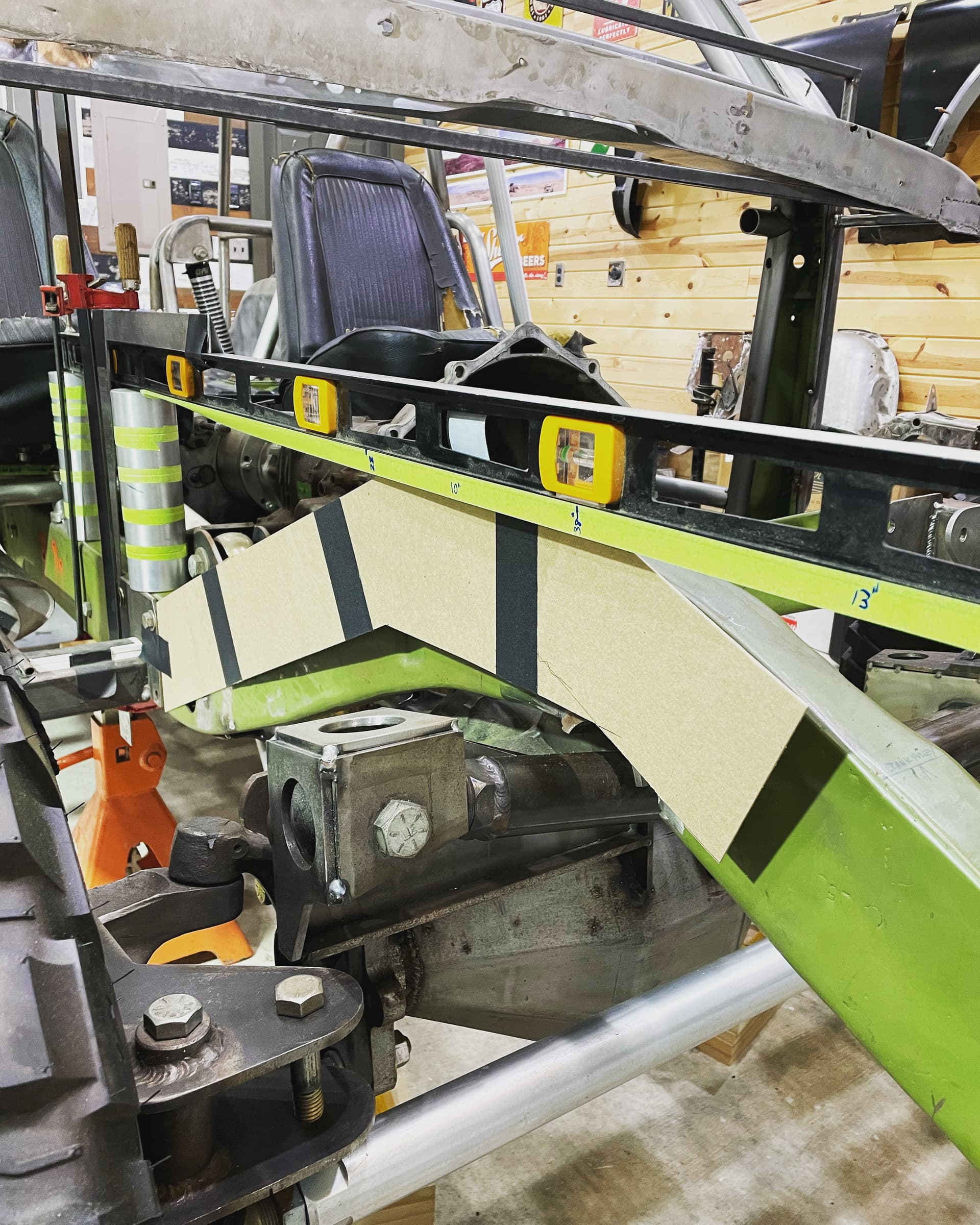
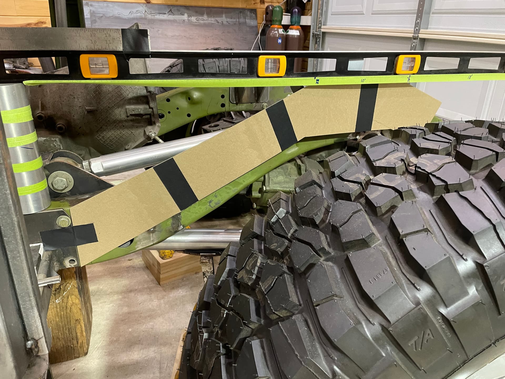
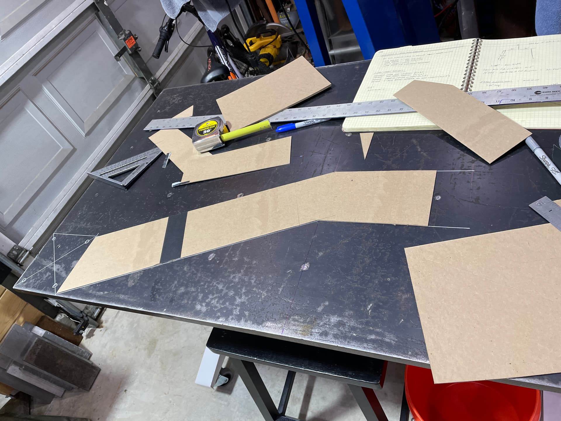
My first “real” project will be a set of rectangular framerails for my 1972 Blazer project. It’s a pretty ambitious step so I’m templating with cardboard to get accurate dimensions and will use those to teach myself how to use Fusion360. My main concern (and the reason for this post) was just to get a better sense of how people actually got though their initial calibrations and proved that their machines were accurate. For sure I want to cut a few small parts to look at kerf, cut quality, squareness, etc. Obviously if there any anything else I did wrong (like my plasma torch front panel settings) I was hoping to resolve those too…
Here’s a shot of the cutting project that I’m preparing for…
100%… yep, you already convinced me on that one and I purchased the radiator you have pictured there… getting that plumbed in along with an actual refrigerated cooler is yet another project that needs to happen… some filtration and dessicant is still needed also. It never ends.
So you were saying in another post that any type of cooler between pump and tank would cause back pressure and add heat to the pump. Do you feel the model you listed above avoids those problems?
I feel that putting the after cooler or what you would describe as an intercooler between the pump and the tank is not the best place.
There are several reasons I outlined in that other post back pressure being one, having to blow off the entire coil every cycle, and I think the main fact is that 60% of that moisture would have condensed in the tank anyhow so it’s doing part of a job that would have already be done whereas if you put it after the tank you’re doing a job that wouldn’t have been done. It seems to me you’re condensing a lot of moisture that would have been condensed in the tank anyhow.
If you ran both scenarios you would get more BTUs and more condensate out of the airstream by having the after cooler after the tank.
Having the radiator between the pump and the tank is a robbing Peter to pay Paul’s situation.
They’re designed for the function and they drain into the tank. Even those systems would benefit from having a cooler after the tank. You’ll also find that those factory ones are not trying to drop the temperature as radically as the home jobber ones nor have the pressure loss.
Another thing you’ll notice is a lot of the time they’ll have mini intercoolers even between the pump heads.