One other caveat is also with the ones between the pump and the tank the radiator subject to the ambient temperature around the tank which is usually the hottest in the whole shop(especially with long run time). So trying to cool air with the hottest air in your shop makes less sense too.
3 Likes
Thanks for the help!
1 Like
I am super jealous! You have some fun projects! Would love to have one of those early blazers. My neighbor has a long bed truck from that era that has been sitting in their backyard for years. I have tried multiple times to buy the truck from them. It’s her dad’s truck who passed and it has a fair amount of sentimental value. Even tried to trade one of my Duramax trucks for it. Her husband was all in but couldn’t sway her! ![]()
1 Like
Just to add my 2 cents. I think the best chance to remove moisture from the compressed air is immediately out of the compressor head while it is hottest and can be cooled to drop the water out. Going right into the tank just adds moisture into the compressed air already in the tank. I believe the concern of adding a cooler between the head and check valve is valid as well.
What about plumbing the check valve after the head and before the cooler to prevent back flow into the head??
The cooler would remain pressurized between cycles and allow any condensed water to further settle out. Appropriate shutoff and bypass valves can be added as desired.
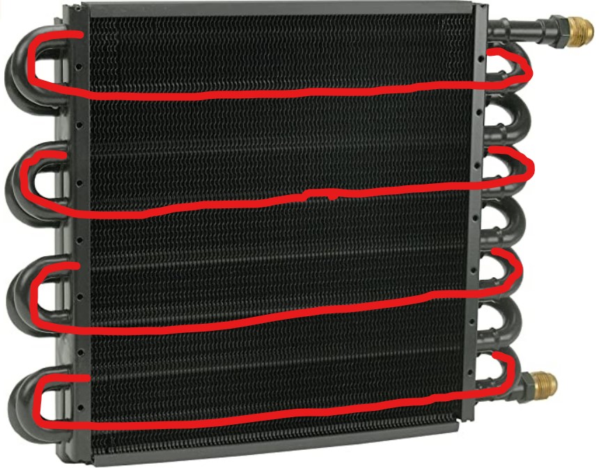
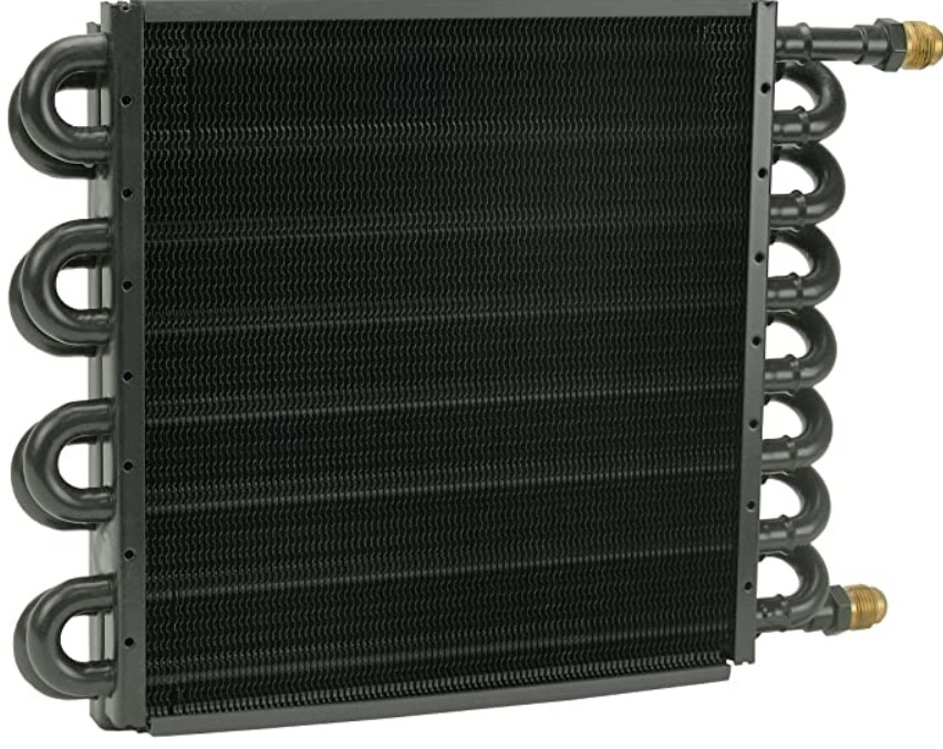
Also, one other question: Doesn’t the design of the Derale 15300 cooler have every other loop returning upwards in such a way that condensed water can collect in the loops? (I have a hard time believing the flowing air would carry it all out.)
-Steve
1 Like
I wouldn’t move the check valve. In the event of a plumbing failure you could lose all your compressed air.
Two check valves??
Also, plumbing failure on downside of tank now will drain tank and/or kick the compressor on.
-Steve
I wouldn’t see the benefits myself. Expensive lessons learned never leave your compressor on when not close by. And always have a cutoff valve on the tank.
On another note I do have a after cooler on my compressor head I see great benefits for it. Mine doesn’t seem to overwork or over heat my compressor… there will still be moisture suspended in the air until you do some serious air drying… the amount of air drying equipment needed is a rabbit hole for sure. Never the less it depends on your climate as far as how much you need.
1 Like
Well that’s the one I’m buying next if my current one fails.
As long as you orient the derale correctly, the runs are all horizontal.
I’ve pictured it this way for a while, perhaps I’m not imagining it correctly.
By saying letting it condense in the tank, isn’t that assuming it stays there long enough to do so?
If I’m using air at a constant rate, then the air in the tank never has a chance to cool down right? So 250 degree air off the pump goes into the the tank, and hits my refrigerated dryer at 250 minus whatever cooling happens on its way there.
But, if I’m dropping 100 degrees off the pump before it gets into the tank, doesn’t that put me in a better situation and keep moisture out of the tank? But, if I’m using at a constant rate, there’s virtually no difference between cooling it before or after the tank, unless you consider the additional tubing run like you describe and the back pressure, which I can see potentially affecting the efficiency of the compressor. I’ll have to time the cycle again once I fix my cooler.
you run at 100% duty cycle ? Naturally during cutting there is a lot a times when air is not flowing . before a pierce during travel, during some rapid time. If compressor is always running it is too small for the application .
The air mixes with the air in the tank in does not bypass it so a lot of heat transfer is happening . Also the tank is normally at a higher pressure then the rest of the system. a regulator is installed after the tank.
When you pressurize a vessel the contents must reject heat . Pressure and temperature are linked.
The tank is designed to capture moisture so what is the benefit to keep moisture from condensing there?
The coil is subject to a pulsing air flow that is at the highest pressure of the whole system ( between the pump and tank) which also means to is also subject to the highest pressure loss because of friction.
After the tank the air flow is not pulsing and at a lower pressure and had also lost a lot of its heat. now the coil is subject to a lower pressure so it has a lower friction loss.
At the end of the day having the coil after the tank will ultimately remove more btus from the system to this point with less work and unnecessary stress on the compressor.
Yes, The back pressure on air pumps will cause them to run hotter introducing more heat into the air.
Really what are the benefits to having the cooler between the pump and tank???
ease of installation?
seeing lot of water come out of cooler that would have mostly condensate to the tank anyhow?
I have trouble seeing any benefit
2 Likes
I can’t speak to the Pro machine since I don’t have one, but my OG Crossfire has no problems being rolled around the shop. I usually use it by a garage door that I open up to let the dust out - it makes a huge frickin mess although admittedly I do not have a water table and probably never will.
The frame on my OG machine is not straight and the slats are not straight either. It came like that from the factory and I fixed it to be acceptable. If I was using it on a production level I would have sent it back but for my purposes it’s OK. My point here is that I have not found that moving the machine changes anything so you should be fine to roll it outside when you’re using it without worry of the frame moving.
1 Like
This is good info, I’m going to copy it to the aftercooler thread and continue there. I think I’m seeing the light I just have a few more questions.
Noticed you did your test cuts with no water? If true be careful running the water table with no water will destroy it fairly quickly because of heat distortion… not that it almost happened to me or anything…
In my case, I decided fairly quickly that there was enough mess (splashing from torch air, dragging magnet in water to get parts, and parts dropping in water and boiling) . My 1st real project ended up building a small enclosure on one end for the electronics (controller and computer) and another enclosure on the other end for the plasma cutting machine. Got nervous that the water was getting too close to all the stuff under the table.
1 Like
@5oh86 The one thing you might not be taking into consideration is that the Crossfire, with it’s cantilevered X axis rail, is only dependent on a single Y axis rail to determine squareness. You could literally fold the frame up completely and the Y and X axis would still be square to each other. Whereas the Pro, with two Y axis rails, is completely dependent on the frame to keep it all aligned, which makes frame twist much, much more of an issue. That’s why some members looking for mobility have built heavy duty rolling frames with pockets for the Pro’s feet.
Sensational! Great Job!
2023.01.18 - UPDATE
This discussion kind of drifted off into an unexpected path… !!! ![]()
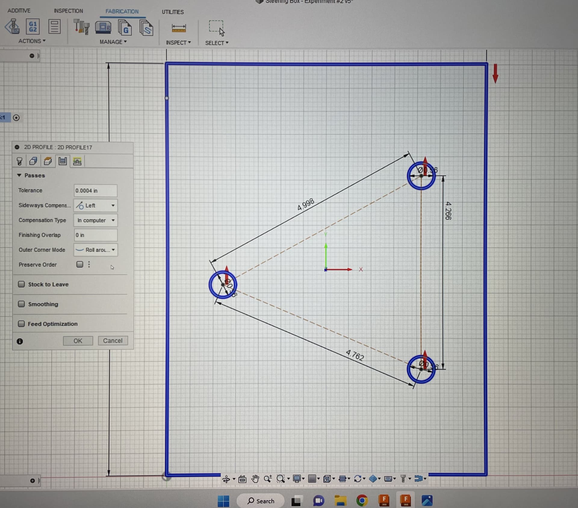
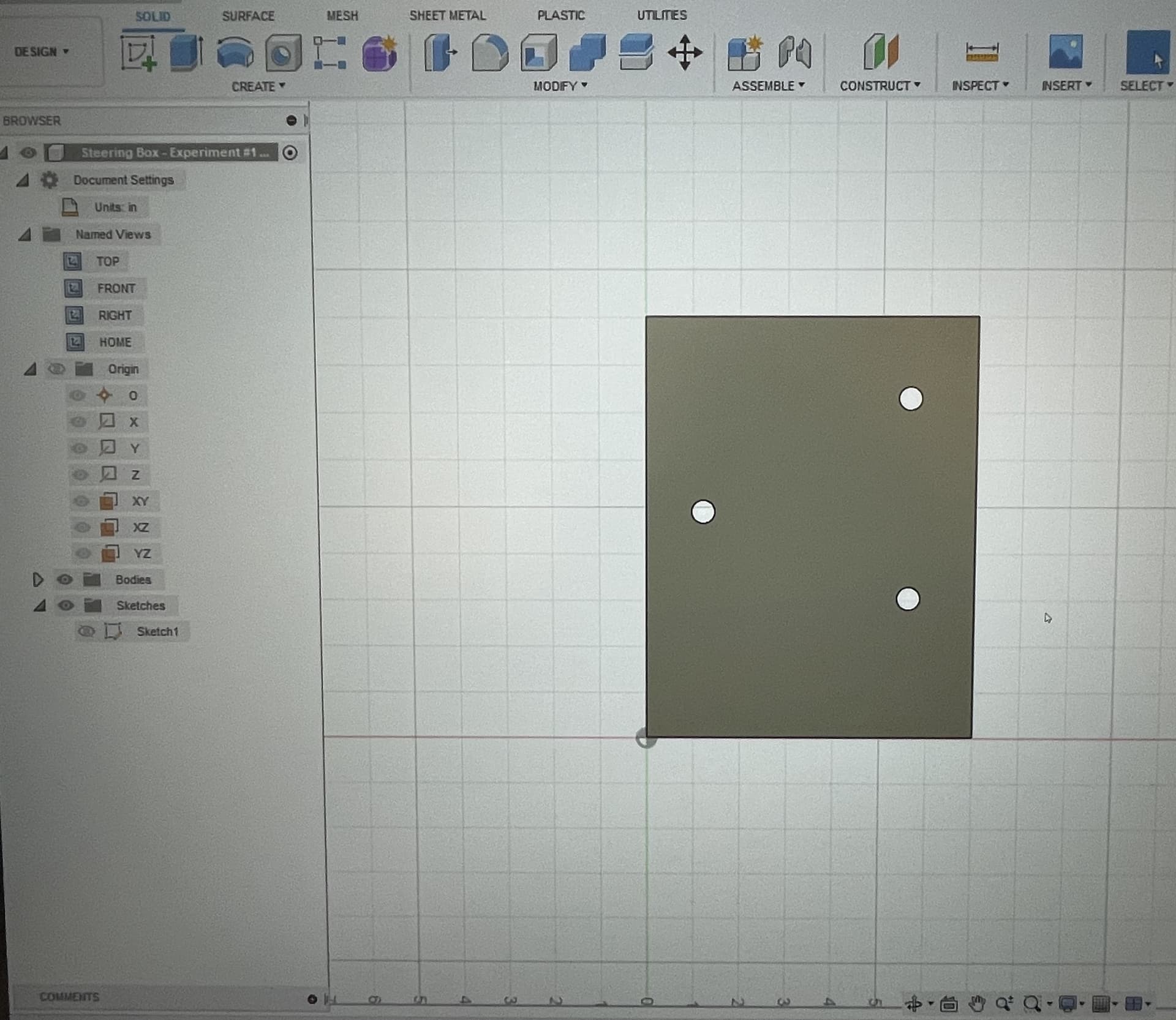
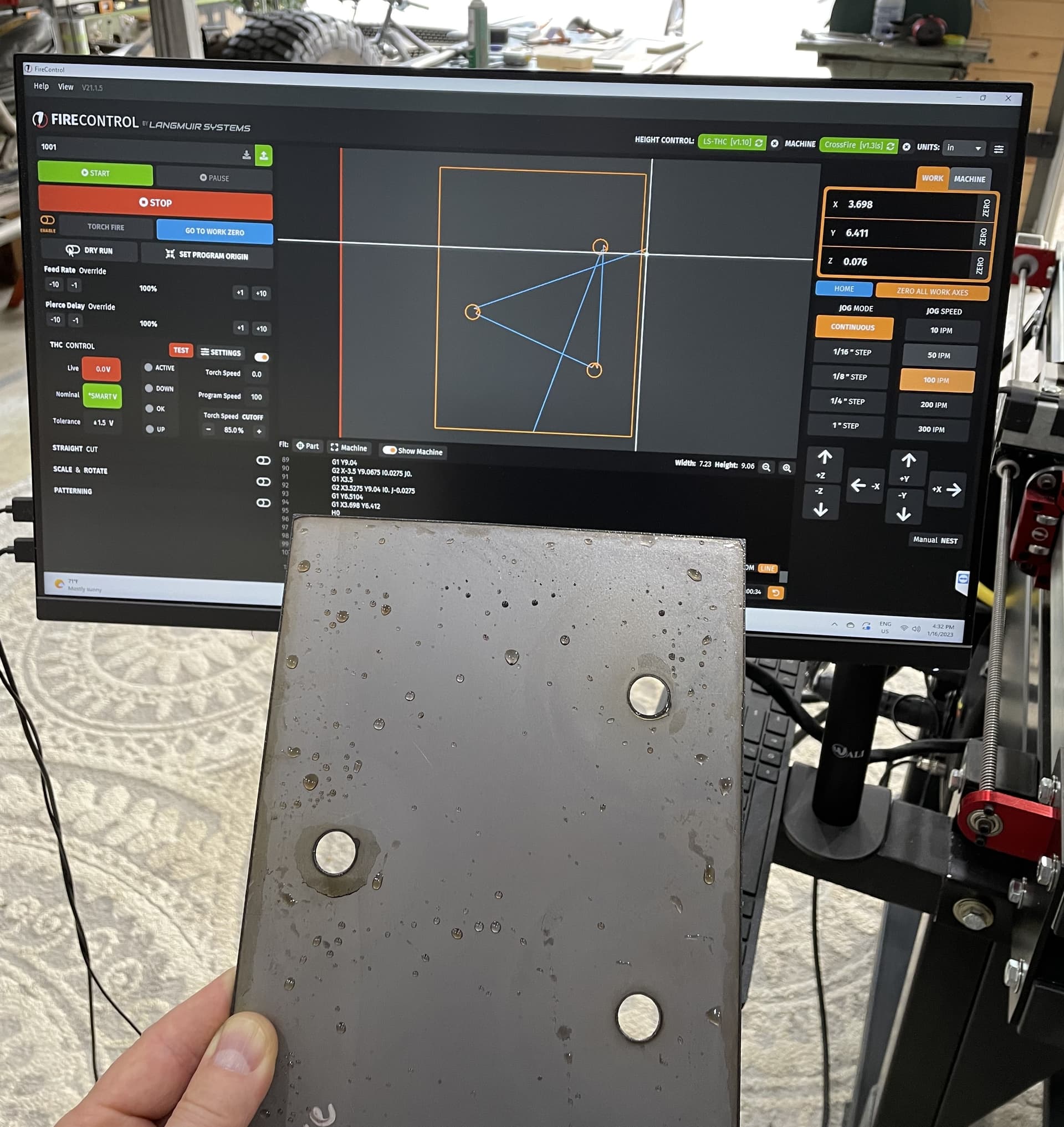
Over the last few days, I’ve been working to get some basic knowledge of the Fusion360 and picked a simple project to build some confidence.
Pulled dimensions off my existiing GM steering box for the 3 mounting holes to see if a bracket could be made as a bolt template.

Wasn’t too hard to get the drawing created. Though I’m still competely confused by the revisioning process in Fusion360 and how/where it is saving my files.
Got it extruded… and tried for a couple of hours to generate a too path. Kept getting an error message about “No Post Tool”?? or something like that… turns out, I had never installed the file for the RazorWeld45, so it didn’t have any attributes to work with. Once I got that resolved, I got a toolpath and was ready to cut.
Here’s the video:

The end result was SO cool… I know that this is the whole purpose of a CNC Plasma table, but for some reason seeing a drawing come to life in steel in my workshop was just amazing to me.
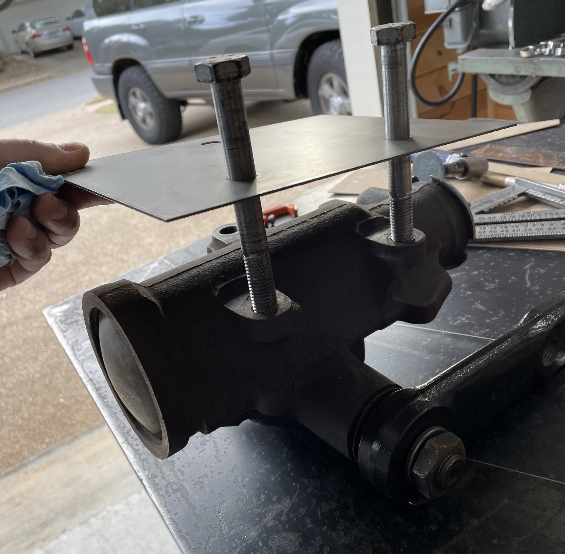
The final test was seeing if I could run the bolts through the template and actually hit the steering box holes accurately. Seems like a perfect fit!!!
So the next steps are:
-
Square up the gantry - On the longer 9" dimension of that plate it is out-of-square by between 1/16" and 3/32"… this should be an easy fix.
-
Overall part size is slightly “under” programmed dimensions - the 9" side ended up at something like 8-15/16" instead, which might be a kerf adjustment? There are a whole lot of adjustment options in the Fusion360 tool attributes for the plasmacutter. I accepted the default settings to start, but I’m sure there are all sort of optimizations that can be made now that I have the ability to program and make more test cuts.
Thanks to the forums for the continued support and encouragement. I really appreciate the community feel this place has, and the expertise and insights provided have made all the difference.
-TM
6 Likes
Personally I am not a fan of Fusion 360. You might consider investing in Sheetcam to generate your toolpaths. It is not as powerful as F-360 or solid works or others, but for 2-D paths it is very intuitive and easy to use.
1 Like
The trick is to have a water separator between the tank and aftercooler. I have mine set up that way and it traps a shit load of moisture before going into the tank.