i have reverse engineered the v2 probe board and figured out a way to get 5v off of the body.
there are 3 things to be done to do this
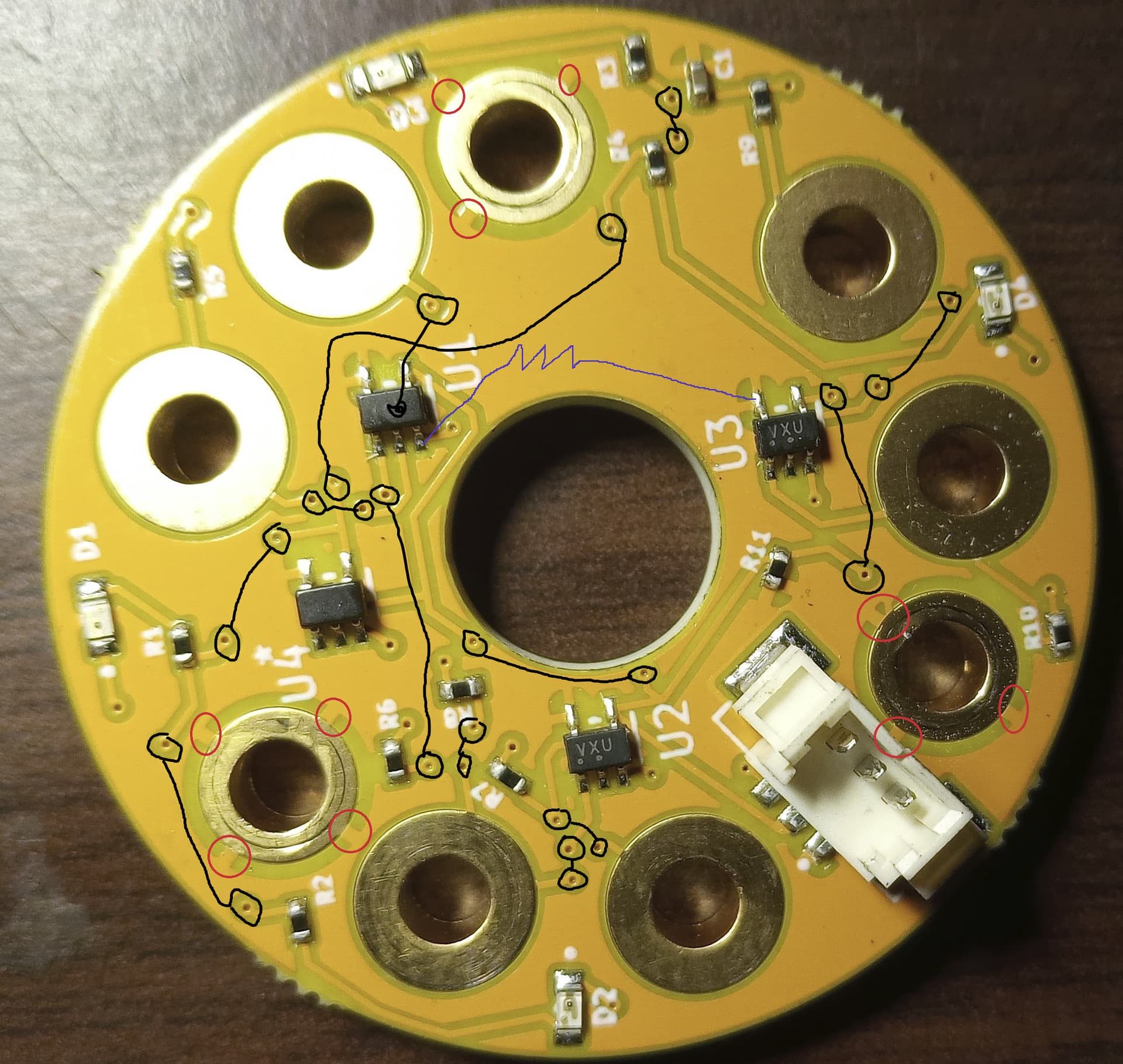
cut traces on the board that connect the mounting screws bosses to the vcc(5v) plane pictured in red circles
isolate the spring from the main body
add 470-800 ohm resistor from one of the 6 balls to 5v pictured in blue(edit the picture shows ground on the pic on u1 use one of the other legs on the bottom just keep it out of the way of the mechanical suff up top)
a brief description on how it works from the factory
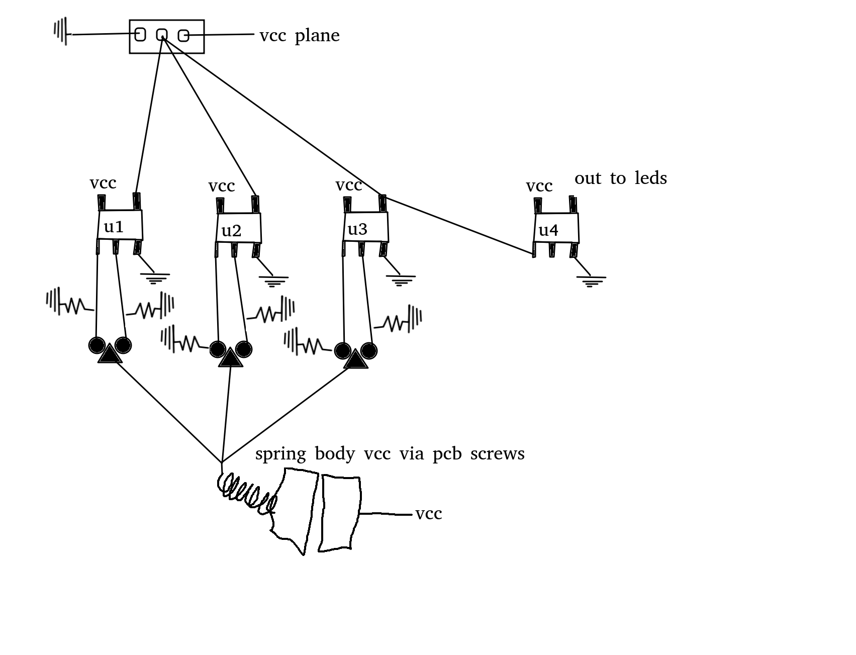
vcc comes in on the connector goes on the vcc plane the mounting screws for the pcb ar on the plane and transfers 5v to the body, it comes down the spring to the probe stem and connects all 6 ball contacts to 5v. u1-3 are analog and gates(or nand forgot the output polarity). so there is 5v on all 6 inputs, if any one breaks contact it triggers the gate and led comes on.
what i did was remove 5v from the body and supply it via a resistor to one of the 6 ball contacts so if any one of the 5 loose contact it triggers that channel. if the one that has 5v on it looses contact all 5 loose 5v.
i did some testing on the resistance needed to pull up the circuit around 1.2k ohm was the threashold for switching in software on the mr1 700 ohm completely dimmed the leds out. so i used a 470ohm resistor. a jumper can be used in its place but that puts machine board 5v on the stem just like factory but only on the stem. if it finds its way to actual ground this will short out the 5v rail on the control board. that is why i used a resistor also the stem body also triggers the probe when grounded.
the isolation of the spring to the body was shown on another post here by @alexw cna’t find it right away but essentially making a plastic spring pocket to the body.
also of note the ground plane of this board is on the other side of what is pictured- the side that gets mounted to the body. the only thing stoping the factory setup from shorting ground to vcc is the conformal coating on the board and annodised surface of the prob body.
ok i have to ask someone to imagine im an idiot and explain what this means to me simply and before you start dont imagine im an idiot because i am when it comes to electronics. i have a probe i just dont know what this does for it.
imagine a hand held power tool with a metal body, the body has live power connected to it. you can use it safely so long as you or the tool do not touch anything grounded. this is essentially the probe in question. langmuir removed grounding on the machine control side to get the probe to work.
That is it exactly. This isn’t the only iffy thing in the MR-1 wiring, but it’s probably the worst. The using ground as neutral on 220V and only fusing one of the 220V legs is also concerning. Using black for DC positive is very non-standard and confusing, but matches how AC is wired in the US.
Do you guys have any recommendations for an “Out of the Box” touch probe solution that addresses this issue. it would be nice to have that option (instead of going through all of the steps you listed)?
Not sure on out the box direct replacement for cut control. For another system, almost any probe will work.
This is the one I use for masso. Alex, You have more knowledge than me on the cut control board. This will take 5v and switch back 5 volts. Is that what cut control wants ?
Sorry, I’m not much help on Cut Control. I wouldn’t want to advise anything without being able to test it first, and I haven’t used CutControl in over two years.
My probe works 95% of the time but it’s that 5% where it will do the Z and then get stuck on either the X or Y that I would like to resolve to get 100% functionality. I have been told that the fault occurs due to voltage “leakage” prematurely triggering the probe. (That is the reason for all the questions about this-) I digress…
I see that the probe Craig suggested is a wireless model. I am guessing that it should be configurable to throw either a PNP (+v) or NPN (-v) signal to the control card.If that is the case, I’m GUESSING that it should be possible to get this probe to work with CC and in theory this would eliminate the leakage issue that happens with the current OEM setup.
That probe is PNP, it returns what ever voltage (5-24v) you power it with
I’m not sure if the OE probe returns 5v to the control board, or if it grounds 5v at the probe. If option 1 then its easy, option 2 will require a relay. A relay will alter to your probe accuracy and will need to be accounted for.
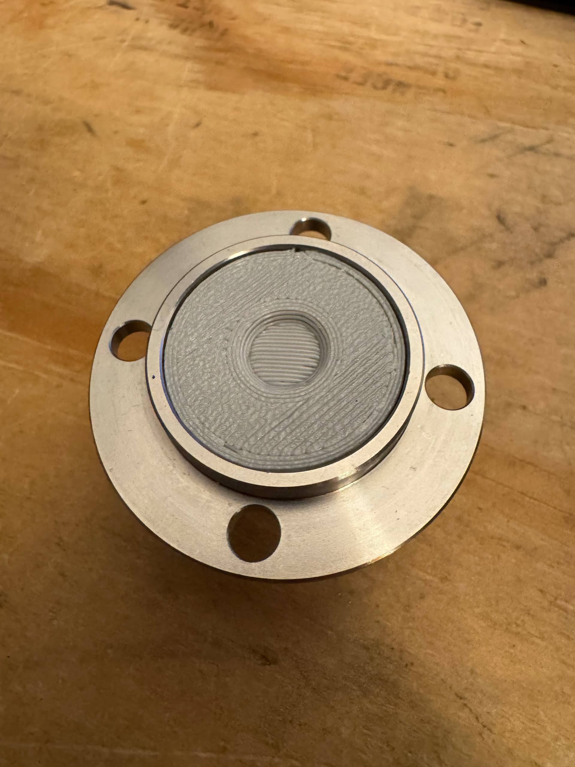
Here’s what I ended up doing. I 3D printed an isolating spacer that goes between the spring and the top of the touch probe.
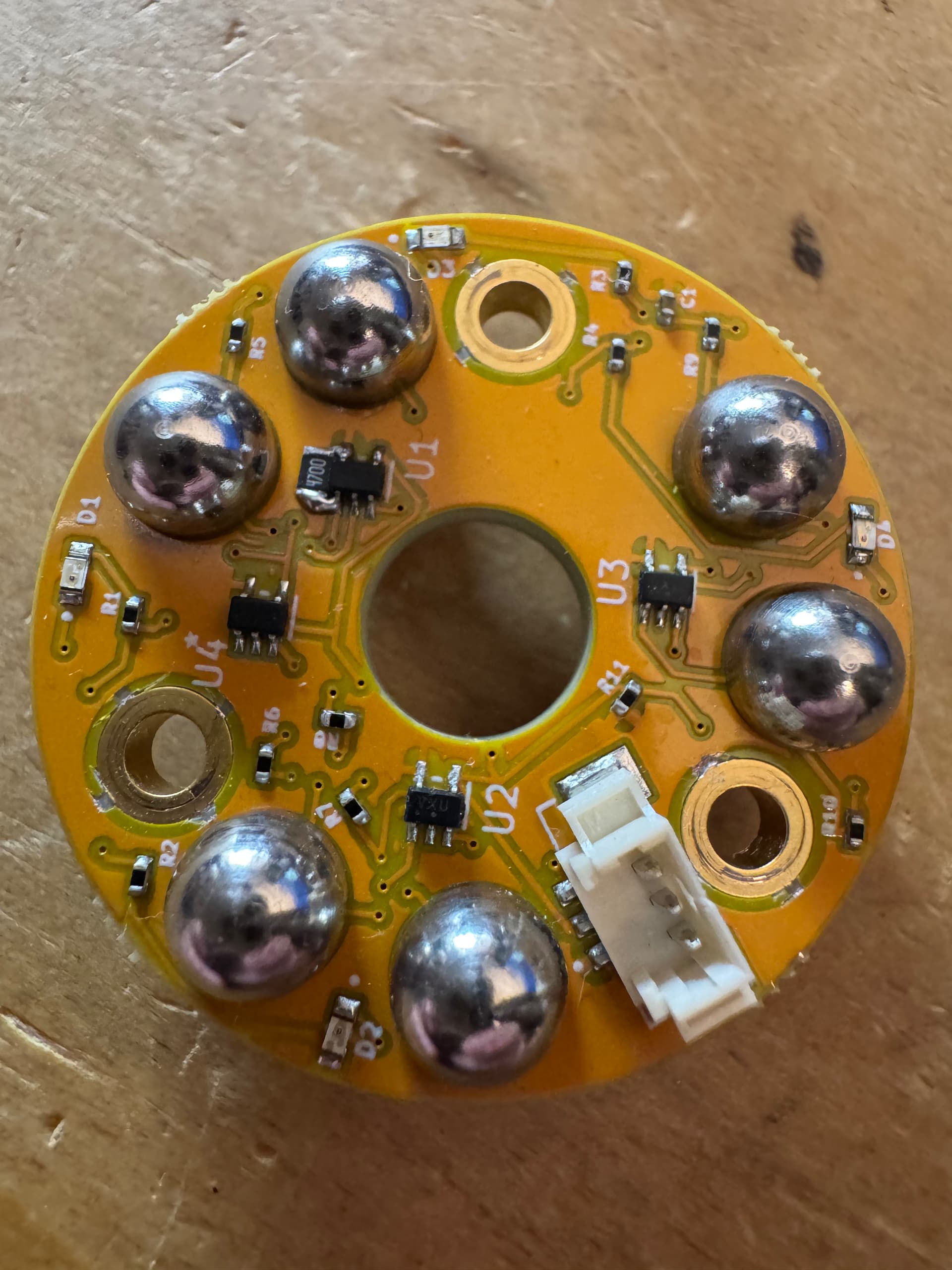
For the PCB, I soldered a 470 ohm resistor (0805 size) to U1 to act as a pull up. I also cut each trace running from the top plane to each screw location. I tested it and it works well!
I ordered a different tool setter since it would be too much of a modification to get the Langmuir tool setter working since the entire top plate is connected to the balls.
just pulled apart my toolsetter. WTF why does this need an 8 bit processor. it has an atmel tiny25 in it. so no easy hardware mods without programming. i think it would be so much easier to just make a new pcb and populate it with a 3 channel nor gate. never made a pcb before might give it a shot.
Agreed … I ended up ordering a “dumb” normally closed tool setter from Amazon. It even has an air port to blow chips off the tools before they are probed which is neat.