Ok…I see we can send it to LS for them to solder it…I wish I saw this earlier…we are just about to install this box…
well you unsolder it and then build up solder to connect the 2 pads… really not that difficult.
don’t know how to or what to use etc.
unsolder? it says to use needlenose plyers to pull off the “inductor”… is that the silver spots on each side? or the black part in the middle? I have emailed LS to see if they can send me a corrected one while I send this back priority or if they can give me more detail on how to do this or what kind of solder etc. I have only soldered a piece of jewelry before …is this simply just making a blob on top of this area? sorry for such lame/newby questions…we were doing so well with the install and now hit a brick wall. thanks, Lisa
For a device in the price range it is in, basically new, etc, it would be wiser to have the manufacturer perform the mod/fix as they would bear warranty and responsibility. For those who have experience soldering, it may not be a big deal. Each person needs to know their limitations, to quote the famed philosopher, Harold Frances Callahan
@langmuir-daniel i emailed the help desk to send it back to fix it, but what is it supposed to look like if i attempt to solder it? what gets pulled off? it looks like silver on the left and the right…is that solder? does that come off or the black piece underneath? if that is solder, can you put a blob on top of the whole area? Does everyone have to do this? if so, i’m surprised there are so few comments on this thread…or is this really that simple? i have only tried to solder a piece of jewelry before and not sure what type of solder, the solder iron etc.? Meanwhile, i am waiting for a response on what I sent today to the help desk…they asked me for clarification on what I was referring to. or have you made a video? thanks in advance, Lisa #11699
Are you sure you’re even having the problem this fix is solving? My table is about a month old and I’ve not made the change, and table is running well. It sounds like you are still in the build stage and have not run test cuts yet. You may not be affected by this at all. I’d keep going with the build.
In the off chance you do run into the interference issue - I agree with other posters here - if you are not comfortable making the change, then let LS do it. It’s under warranty - let LS fix this for you if you run into problems. I’ve got experience soldering components like this, but I’d probably still have LS do it - just on principle. From what I’ve seen/heard the customer service is great - let them take care of you! 
You’ve got way more patience than I do ![]()
…well, if I was in a bind…I might throw principle out the window…I’ve never done that before 
@langmuir-daniel I still think a video would do alot of people good.
Oh really! James5 I thought this was something that had to be done! Especially since they said they are redesigning it for the 3rd batch. We were just at step 14 to do this install when I read this article. I will wait for their reply but most likely will continue on with fingers crossed!
it’s a relatively simple thing and you could always try locating a discarded computer board and practice de-and-solder, then test the connection using a DVM for continuity. the danger is using the wrong tool and overheating (melting something you shouldn’t) or creating a cold solder which “looks” okay but isn’t.
again (Harry Callahan), “do you feel lucky?”
It sounds like it’s a good idea to do it regardless - they are stating it will make the machine more resistant to EMI and they are going to update their boards going forward. I’ll have my machine updated either by myself or by LS at some point, but if you are not experiencing the EMI issues, you can get up and cutting and make this update at a more convenient time. You may run into the issue right away, but my understanding is that it affects < 10% of users (don’t quote me on that). These machines run in an electrically noisy environment, so making any improvements to shield the control electronics is a good thing.
Maybe there is a radio repair shop around where you all live? they could do it blindfolded. And save the mailing time on it to LS. Or I guess a pc repair place also
Great idea…
for anyone that has no confidence in their soldering abilities (like you have no soldering abilities) its incredibly easy and one of those things that is very indispensable. you need minimal tools to do it. and once you learn how to do it (about 10 minutes of seat time) you will be able to fix LOTS of stuff.
im considering doing the mod and video taping it just to help others but i dont have any issues with my machine so im still up in the air with it
here is a list of items you will need
Soldering iron
electronics rosin core solder (not thick plumbing solder)
rosin based flux (below video doesnt mention the need for it because the solder has flux however flux basically will make solder stick to everything much better and you can pre apply it before you heat anything up i flux literally everything use very small amounts it should last you years and years)
DO NOT USE ACID BASED FLUX acid flux is a liquid it works great for bonding metals but ruins electronics and wires… rosin flux is like a brown paste usually comes in a small tub or a syringe
wet paper towel, a wet sponge or the little gold brillo solder pad for cleaning the iron (paper towel actually works the best IMO)
optional stuff
stand for the soldering iron
here is a video that goes through what you need and how to do it.
if anyone needs help and you live in nj i would be more then willing to do it to minimize downtime
also if anyone needs any tips feel free to dm me…
you can absolutely do this its very straight forward it will open up the amount of stuff you can do as well
i was actually thinking of doing the same thing so i was going to make a before and after video of when the torch stays stuck ON with cutter right next to control box because of the interference so i placed my cutter right next to the control box, loaded a simply file and hit record on my phone and started the cut. IT DIDN’T HANG UP!!.. lol
weird that it used to before. I cut a few small things and didn’t hang up once. so i guess no video for now.
I performed this mod and unfortunately it still has not resolved my issue. Langmuir sent me 3 additional chokes. So I have 6 chokes on it (including the 2 built in chokes) and I have consistently had issues with Arc Fault.
To be honest, I’ve yet to have any real success with this table. I’m wondering if I just got a bad unit. It’s been extremely frustrating.
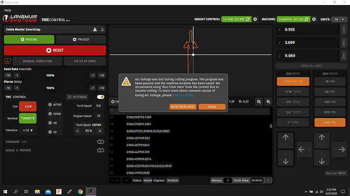
Error I get:
In this instance I was using a free GCode on the Langmuir FireShare. But it doesn’t matter what I use, FireControl constantly locks up. I’ve tried every possible distance from the Main control box to the Plasma Torch, doesn’t matter where I place it, Arc Fault, Arc Fault, Arc Fault. I’ve wasted a ton of material at this point.
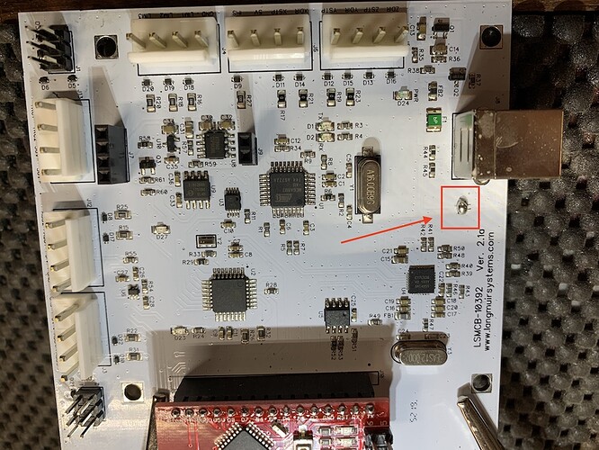
Here is the mod. Looks right?
Any additional insights @langmuir-daniel? Any way to determine if I just have a defective unit?
The arc voltage lost error is NOT the same result when interference is at play. Interference causes your laptop and/or FireControl to freeze up. If a Arc Voltage Lost error was shown to you, then FireControl isn’t frozen.
Is your THC working properly? When its cutting are you getting a healthy voltage displayed? The arc voltage lost error pops when the voltage is less than 10 volts during a cut. Theres only two ways that can happen. One is you have actually lost arc voltage (or didnt establish it in the first place if a misfire occured), or your THC is not sensing the voltage properly.
Interesting, when I emailed support, they said it was interference that was causing the problem…
“We’re going to send you an additional two ferrite chokes to connect to your USB cable. While you are waiting for that, can you try to do some cutting with THC disabled in FireControl to see if it still freezes?”
Before it didn’t seem to make a difference. However with the mod in place now, when I turn THC off, it does appear to be cutting… Suggestions?
Of note, I see that I have 2 blinking yellow LEDs on the board now… ‘TX’ and ‘RX’. Does that help with troubleshooting?
Also, how do I check if I have healthy voltage? I don’t see it showing up on FireControl. I have ‘Nominal’ set to ‘Smart’ and the Live voltage box (red box) never has anything in it…

