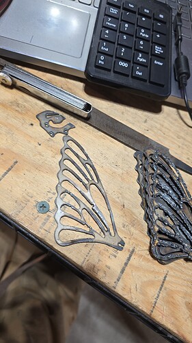
Thank you. Im working on a butterfly out of 16 ga. Steel. The thin stuff is a challenge. I have cut 20 test wings but not happy with the quality of cut yet
16 gauge is still plenty thick, if it isn’t 3/16" or 1/4", 16 gauge is my other most common gauge I cut.
The finished product looks good! But some constructive criticism regarding your cut outs -
The heavy bottom dross shown on the parts to the right tell me you’re moving way too slow
The “notches” in a few of your inside cuts can be helped by adjusting your lead in angle/distance as well as adding a bit of a radius
And, even though the parts are small, maybe alternating your cut pattern to perform one cutout up top, then the next one at the bottom, alternating back and forth which adds a little bit of time in between to help keep things cool
I’ll preface by saying I don’t care for Football, anyway here’s an example of a small cut out on 16 gauge
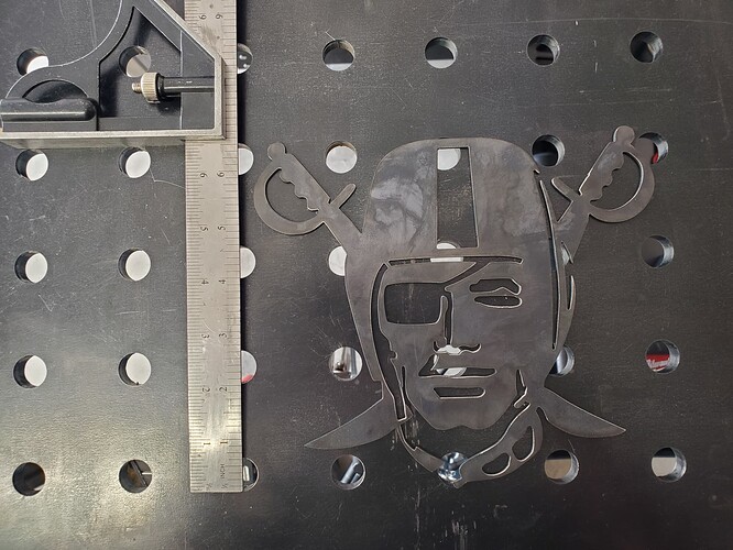
I agree with most of that. Most of my cutting is timber frame brackets and farm repairs/ mods. In other words 1/4 and thicker. So using THC is still new to me. My speeds are what I was working on there. Those are 140 to 180 IPM range. 150ish seems like the “good” speed. Best cut least dross. I post process at 180 then use fire control to adjust speed. All my cuts are programmed to alternate as far away from eachother as possible. I even program the perimeter cut to pierce opposite the last cut. I use fusion 360 so it likes to discard cuts that are too close. I have my kerf set to .020 but fusion still likes to discard. I work my day job in construction management, so the metal I test on is free but its also scrap filing cabinets and access panels, I even have a pile of standing seam roofing. That stuff cuts awesome. My point being is yes I know about lead in and lead out but those were not what I was testing. I mostly wanted to see if I could cut a slot and tab design that small and what the best speed was. The funky little piece in the upper left is just a widget drawn on f360 with a few dots and a 1/4 long slot that is .030 wide the 3 holes are, believe it or not, circles starting at .030 then .035. And .040. They get progressively closer to the edge in an attempt to test burn through. That whole piece is the size of a quarter.
Ah gotcha.
You can disregard my post then, I was simply responding to the post right above mine without any regards to anything you mentioned earlier. Didn’t realize there was more going on!
No, no need to disregard at all. I am always willing to learn. My last post was intended to discribe my means and methods, not dissuade you from a teachable moment. I am 1 year into this CNC world. I welcome all advice…within reason. I have read some posts on here that I thought were satirical only to keep reading and realize they were serious.
Yeah I have some notes as well. You should start a new thread, I’m confident we could get you tuned up to where you won’t need to cut so many examples.
So the biggest thing is what cutter and consumables are you using? You’re limited by your kerf size.
Also; are you applying any rules to cuts like to slow down in corner and what not? I know you’re using fusion, I use sheetcam so I’m not familiar with all the fusion terminology.
If you’re having to change your kerf in fusion to get details to cut, you’re basically robbing Peter to pay Paul. That may allow the path to generate but the path won’t be accurate because your kerf likely isn’t .02. So you’re losing more metal than you’re accounting for.
If you opened up your design a bit it would solve a lot of problems. I’m guess you’re running standard consumables at 45 amps by the look of the cuts and the heat markings. At your stated IPM that’s took slow. The thing with the thin stuff and fine details is the dross is almost unavoidable on the details. It will come off easily with a wire wheel on a grinder and a flap disc for maybe a couple spots, but it’s a park of doing business on thin detailed 16 gauge.
another thing about kerf…
kerf is what is removed during the cut…you can not actually change the kerf in any software…
if you do change it in software it is only a visual change and not an actual physical change to the cut…
The actual KERF is dpendant on the tip size (0.8 , 0.9 , 1.0 , 1.1 , 1.2)…and amps…
if your actual kerf removed is say 0.060 with a 1.2 tip…and you change it to 0.045 in the software…it will still cut 0.06…but will show on the screen as 0.045…
To piggyback on this information, changing one’s torch height will also alter kerf width enough to measure the difference.
This is more apparent on thicker steel naturally, but torch height will change the physically measured kerf.
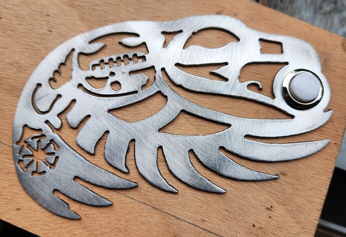
I was tasked by my daughter to make this door bell decorative plate that was about 3.6 inches x 5.7 inches.
I had to sacrifice quite a lot of detail and got to this:

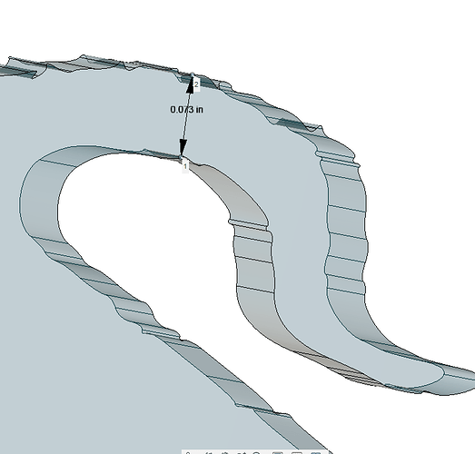
But you can see with the dimension of the tongue, I was still going to have trouble:
Normally I cut everything with 45 amps. This was 16 gauge so that would be at 249 ipm which would be a kerf width of about 0.053 inches. Every time I tried this, I would lose lots of detail. Another member had written about experimenting with less amperage on 16 gauge (@Cletus). He wrote that by decreasing to 30 amps and running at 150 ipm, the kerf was drastically reduced. Even though we have different cutters, I tried his numbers and this was the result:
So as ToolBoy suggested, decreasing your amps could be another possible gateway to success.
I did not have any Fine-cut consumables at the time. That is another option if they are available for your cutter.
If you want to check out some crazy detail:
I have the razor weld razor cut 45. I am using consumables that I bought on the site when I ordered the XF PRO. I bought 5 electrodes and nozzles. and 2 of everything else. When I got the cutter, the hand torch was sealed in the box and it had consumables in it that were Hypertherm. I have a picture somewhere. I took those out and put in the ones from Langmuir. I have done a few dozen kerf tests and the smallest straight line cut I have measured is .028, most are around .030 That is middle of a 3 inch cut at 200 IPM on 16ga with new electrode and nozzle. Pierce and stop are different All of these measurements are with a digital caliper ($60 cheapy) so I wouldn’t put a ton of stock in accuracy. Again I am not shooting for smallest possible results, but rather smallest repeatable results.
I do apply rules on corners and circles. I have been testing those also. The good wing was 90% slow down. Those wings are pretty small, about 4x3. the other pile was working up to that from 60%. The design I am cutting was made for a Laser, to cut Luan. I’m trying to adapt it to the plasma. Ultimately I think you are right I may need to change it a bit. My plan was to make half the butterfly from wood and the other half from metal.
The problem with increasing the speed to much is the detail suffers The dross is easy enough to clean I just toss the parts in a media tumble for a day and that knocks off the majority of it. I program the cuts with the knowledge that they will be about .015 to .010 over actual. I adjusted the laser cut wood parts to account for that. It would be cool to do a wood and steel wing sandwiched.
I have been building high end custom Homes most of my life. I understand Kerf size. I get a reminder every time I train a newbie. 1/8" short crown molding really sucks. The purpose of the kerf adjust in the software is just to convince the program it can cut what I want it too. A 3 inch tenon wont fit in a 2 inch mortise just because you wrote 3 on the wood.
Cut height is close. I started at .060 and am down to .045. these are measured heights using feller gauges. I have found that as consumables wear the kerf increases. which makes sense. I am of the mind to replace before I lose trace,( the line that you scribe on wood to cut up to but not beyond) when it comes to detail work. Better to be tight and wear in than loose and wear out.
I have been cutting at 45 AMPs. that might be the ticket to better cuts.
Sorry for the hopscotch reply. Currently dealing with sewer inverts not being as planned in civil drawings and the nightmare of pre-ordering 18 pre-cored storm water structures that no longer work due to a higher then planned sewer line.
I remember seeing this on the forum awhile back also. Very impressive
@ChelanJim @murphysean73
thanks guys…
on that cut it may look like details were missed but in actuality very little was missed…it was a copy of an artists comissioned work for the family heads birthday…a little abstract but detailed.
First the consumables on the torch were not Hypertherm. They were Chinese copy’s made to look like Hypertherm. Second the Langmuir consumables are also not Hypertherm.
Some people have used real Hypertherm consumables on the X45 machine torch and the hand torch and sometime they work. Most of the time they do not work as they are made differently.
Do the chinese knock offs have Hypertherm logo and part number etched on the nozzle and electrode?
Correct. That is the aperture of the nozzle that is increasing with wear. I have found that I replace that more often than any other part. You will also notice an increase of bevel.
I did order some Hypertherm consumables from Langmuir and they are genuine Hypertherm. If not, they went to great lengths in the packaging and the identification on the parts. Prices are very similar to Baker’s Gas so they are not really any cheaper.
No. The purpose of programming the kerf size is so the software will offset the toolpath to accurately cut your part. That’s why there is an inside and outside offset (sideways compensation in Fusion).
If you tell the software your kerf size is .02 it is going to move the tool path so the center of the torch is in a different location on the path than it would be if you had entered .08. This will result in an incorrectly sized part.
I agree completely.
The problem with increasing the speed to much is the detail suffers The dross is easy enough to clean I just toss the parts in a media tumble for a day and that knocks off the majority of it. I program the cuts with the knowledge that they will be about .015 to .010 over actual. I adjusted the laser-cut wood parts to account for that. It would be cool to do a wood and steel wing sandwiched
Perhaps I should clarify. The Razor Weld Cut 45 I ordered as part of the package with the Langmuir Crossfire Pro table, came with Hypertherm electrode and nozzle already installed in the hand torch. The Electrode and nozzle, both had Hypertherm logo and part number laser etched on to them. Different part numbers on each piece, however they are the correct part numbers that correspond to actual hypertherm, part numbers for those same pieces. I had read enough on the forum to assume that that was the incorrect parts for that particular Torch, I ordered razorweld consumables from langmir when I ordered the table, I took out the Hypertherm. Etched parts and replaced them with the parts that langmir sent me as replacement consumables. The replacement consumables that langmir sent me are not identified or marked in any noticeable way.
If you put in too small a kerf size…. It takes away more material because it puts the tool path closer than it needs to be.
I guess bottom line though, if you’re happy with your process then keep at it.
