Man are we spoiled.
2 Likes
My 30th anniversary of first walking into a tin shop for a job (which was work experience for high school) just happened on the 15th of this month. And sometimes when I forget how easy I have it I like to watch this video
just fabricating kitchen wares in the grass while trying to raise his family. so crazy. They did what they had to do.
4 Likes
This method is called triangulation. And so far it’s the only way I can get fusion to deal with compound curves to flat patterns. And you’re completely correct the smaller triangles you go the more accurate the model.
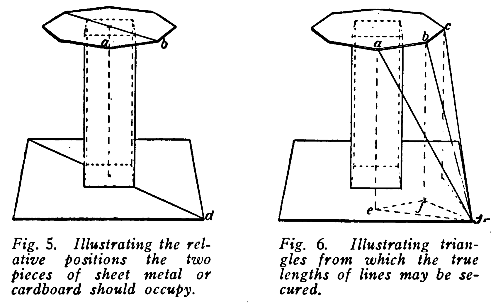
Here’s 100 year old description of the technique
“TRIANGULATION CHAPTER I. ELEMENTARY PRINCIPLES. Triangulation is a term which has in recent years been applied to certain operations in Sheet Metal Pattern Development, although said operations have long been explained in works upon Descriptive Geometry, where is found the declaration that the true length of a right line in space may always be found in the hypothenuse of a right angled triangle, whose base is equal in length to the horizontal projection of the line, and whose perpendicular is equal to the difference in length of the vertical projectors from the extremities of that line. Triangulation as applied to sheet metal pattern development, is the act or process of dividing into triangles, also the results thus secured; specifically, the laying out and accurate measurement of a network of triangles presumed to be upon the surface of the object, and shown upon its geometrical representation which has been correctly delineated. Triangles with which we deal are considered as plane triangles, although not strictly so, since a plane triangle is presumed to lie in one plane, and is bounded by three right lines. A triangle which is presumed to be a portion of the curved surface of an object will not lie in one plane. In many instances one side at least of said triangle is not a right line but a curved one. Thus many triangles involved in triangulation as applied to sheet metal pattern development are mixtilinear triangles. However, the magnitude of the variation is so small, that it may consistently be considered as a negligible quantity.”
this book has a lot of different examples of how triangulation can be applied. I have a small library of books like this in my office.
3 Likes
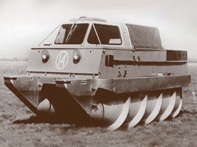
You know, it is funny. I was just thinking “How do they make augers?”
But I couldn’t make them because I don’t have this specialty tool:
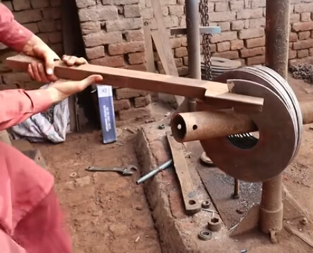
![]()
I really enjoy watching those videos. Even the hole size intrigued me: perfect.
That does give a solution for the twist for the metal with your project: of course you are always 3 or 4 steps ahead of the rest of the class and already are there.
1 Like
model rockets?
3 Likes
Blades for my wife’s iRobot roomba.
3 Likes
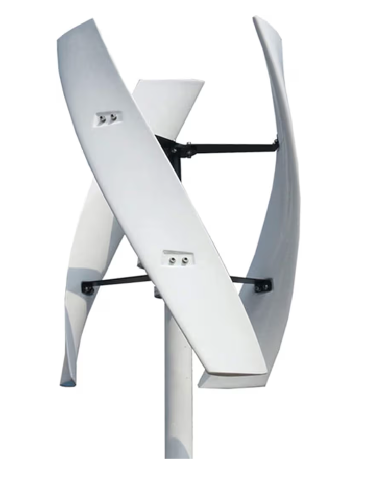

Edit: I just noticed this gif model is actually incorrect. the fins should be spiraled the other direction on one of them and spinning the other way to go forward or backwards
3 Likes
That reminds me of a joke. A farmer notices that his horse keeps hitting his ears on the top of the door opening. He decides to dig a trench at the doorway.
An ignorant friend drops by and says “Not going to help what you are doing. It ain’t his legs being too long, it is his ears being too tall!”

![]() It is nice having my very own illustrator (Project Salvador - Beta)!!!
It is nice having my very own illustrator (Project Salvador - Beta)!!!
3 Likes
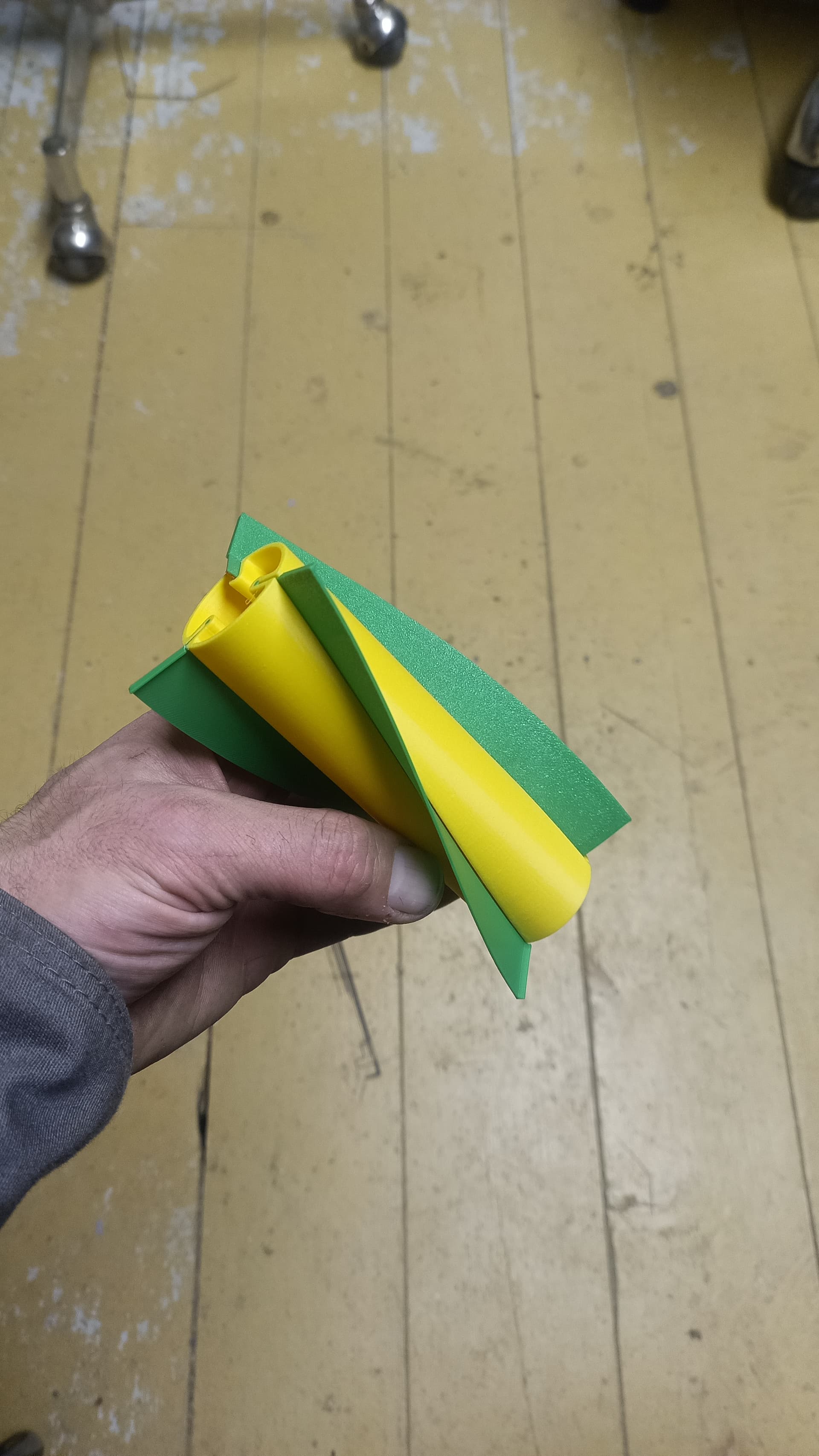
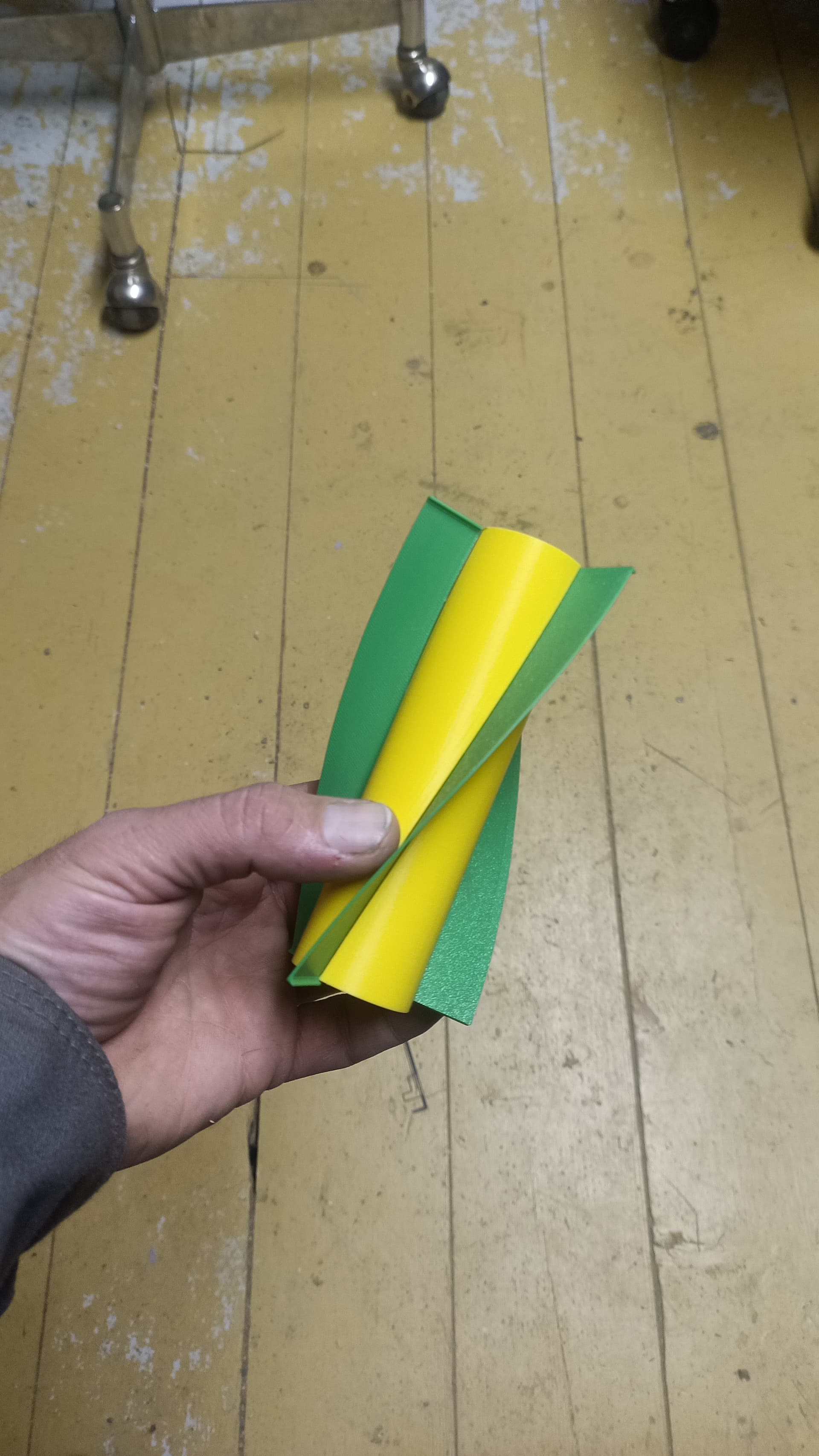
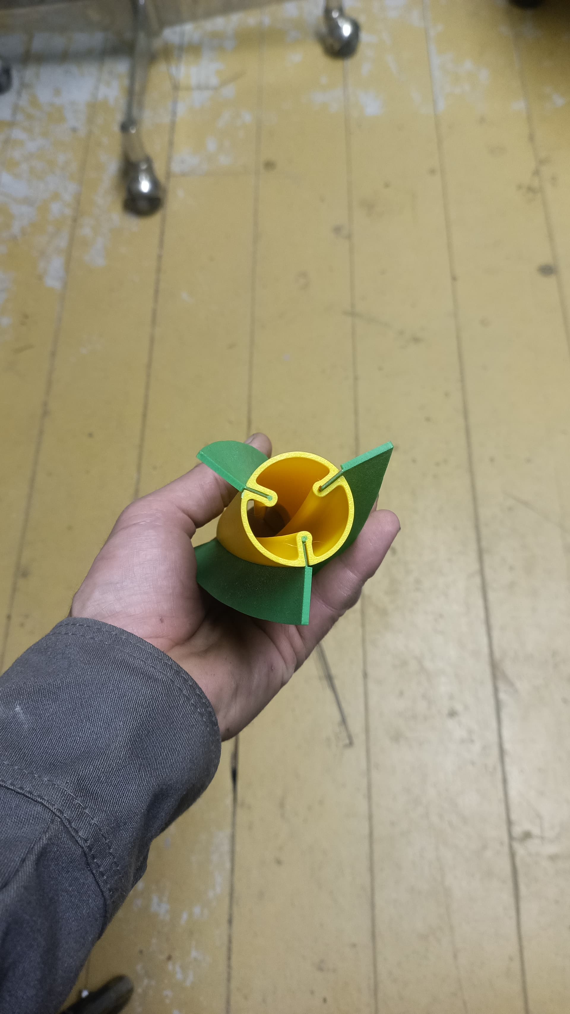
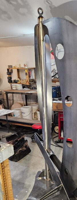
I cut out and mounted a real world steel example of these twisted forms.
Our methodology seems to work very closely.
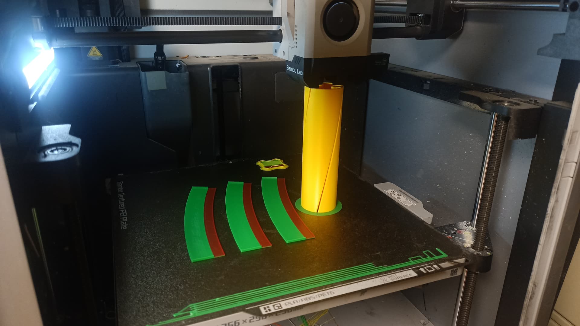
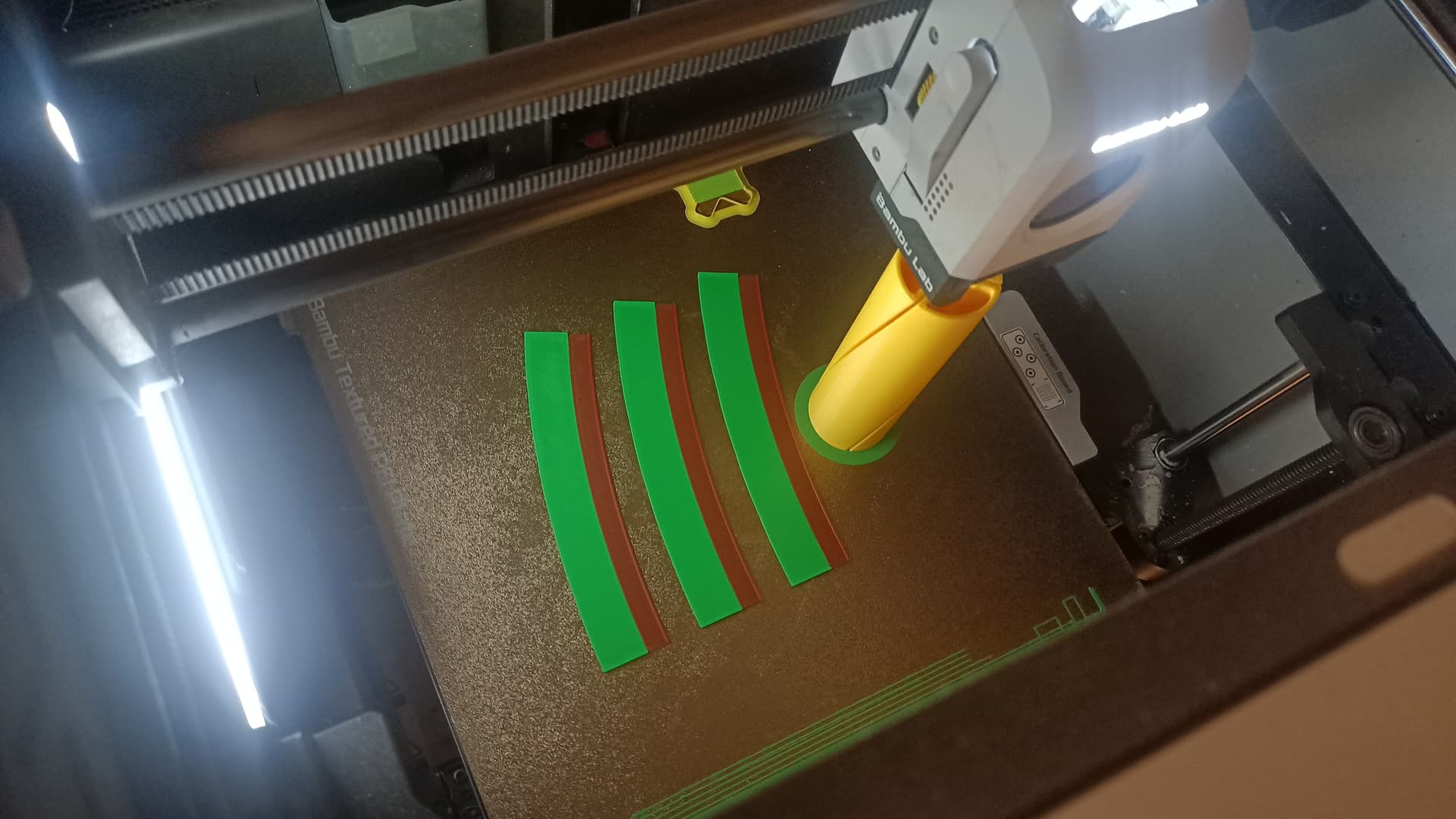
For anyone still playing along here’s the print profile for testing fin flat pattern
Tri Fin test model. Twisted Auger form by fourthstatecnc MakerWorld: Download Free 3D Models
Have you decided how you are going to make this compound twist?
Edit: I see, you have already done your necessary pieces for the sculpture. You are doing a theoretical exercise at this point for future projects?!
You are building a space ship!!! Craig was right:

I legitimately want to find a simpler method that is more accurate. Even though the method of I currently have is quite accurate.
I also think other people that would want to use this kind of form could benefit from this topic.
1 Like

Definitely. Very much a worthy cause and ground breaking. I was just afraid this might be holding up your project.
1 Like
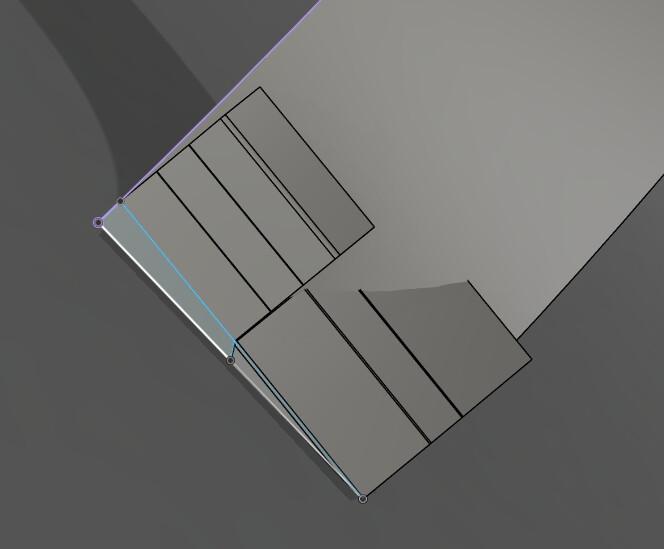
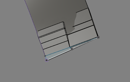
Okay, so I went totally off the reservation on this design. I started with the sliver at the bottom but cut it in half. This gives me some latitude to follow the blade more closely with two halves having flanges.
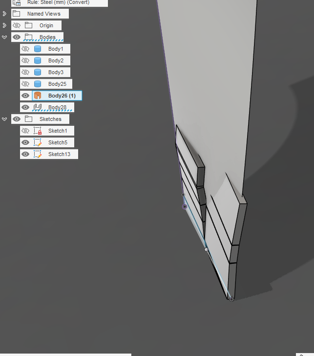
As I worked my way up the blade it is not looking very pretty and is not stretching to fill in the full width of the blade. I am keeping with the 2 inch fin, 0.075 inch thick metal. To correct for the blade not reaching all the way, I extruded each flange.

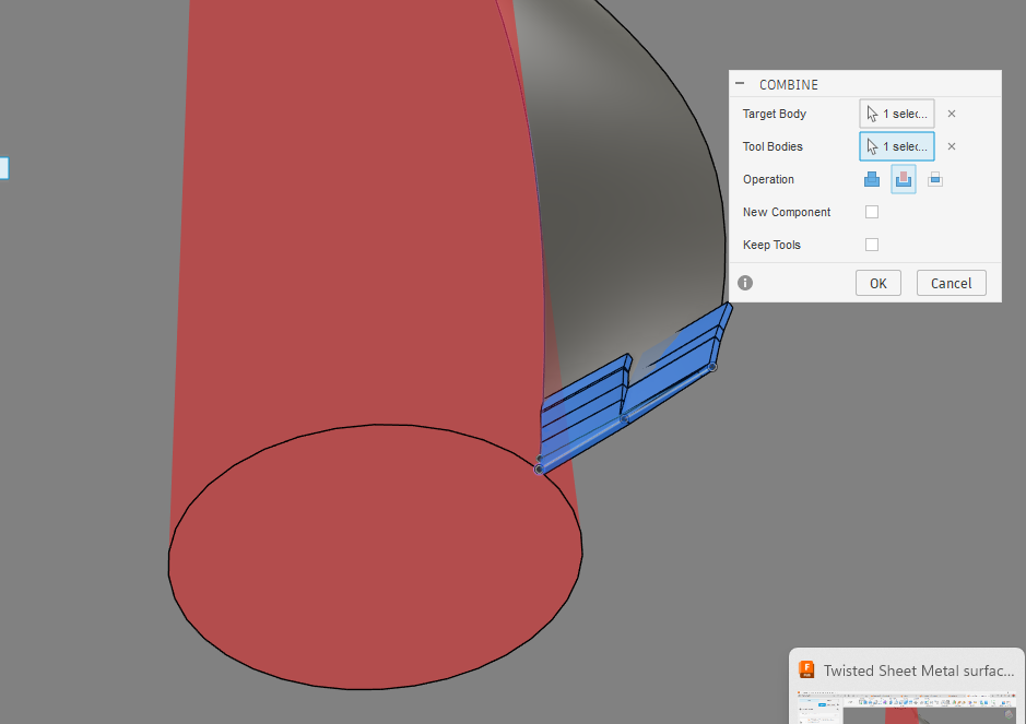
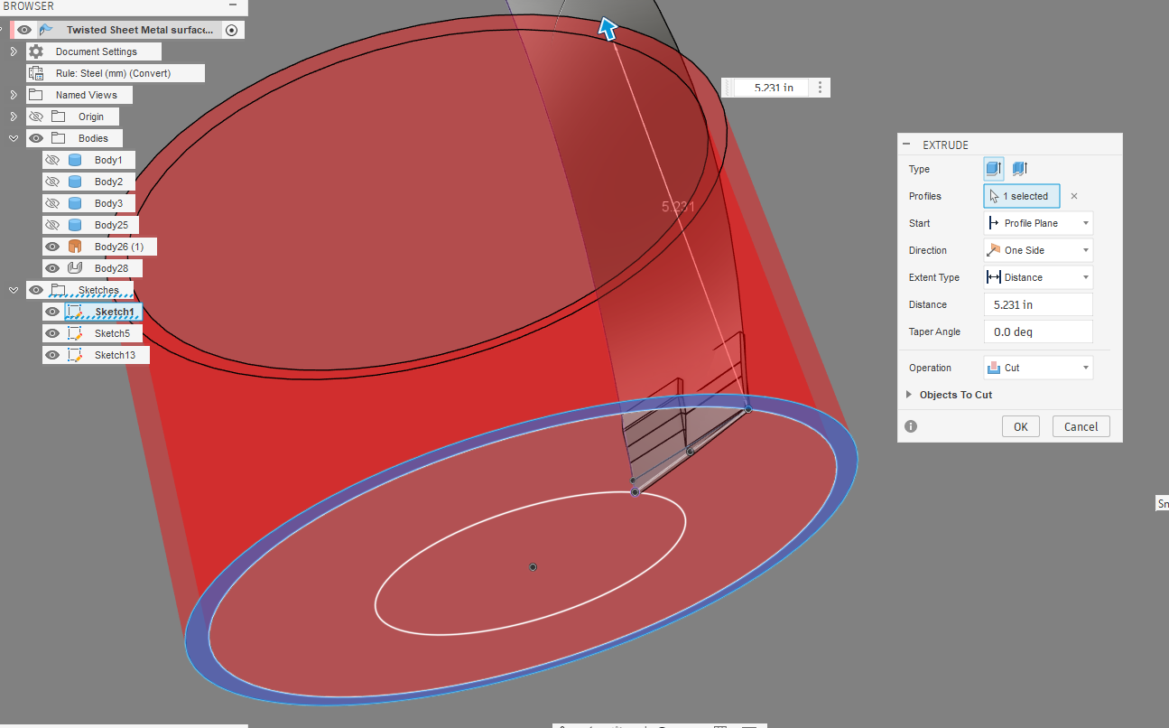
I used the center cylinder to trim the inside. I added an outer rim to trim the outside.
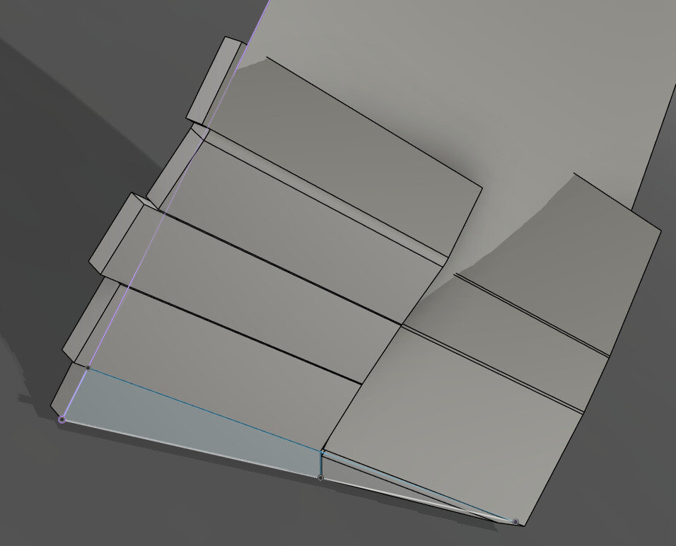
Now the flanges are fitting a bit better.
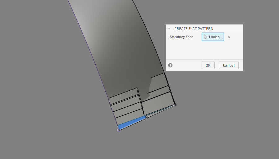
Time to try the flat pattern
It reveals that the dimension is a bit over our 2 inches so it is showing a little stretch.
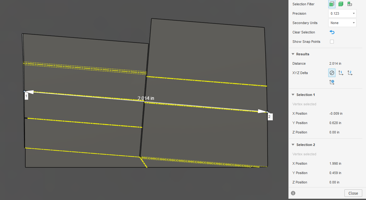
But I think the diagonal measure is showing more than it really has. I also thought I should extrude one of the flanges on the right toward the center. It allowed it and made a flat panel but you can clearly see that flange is colliding with the other side now.
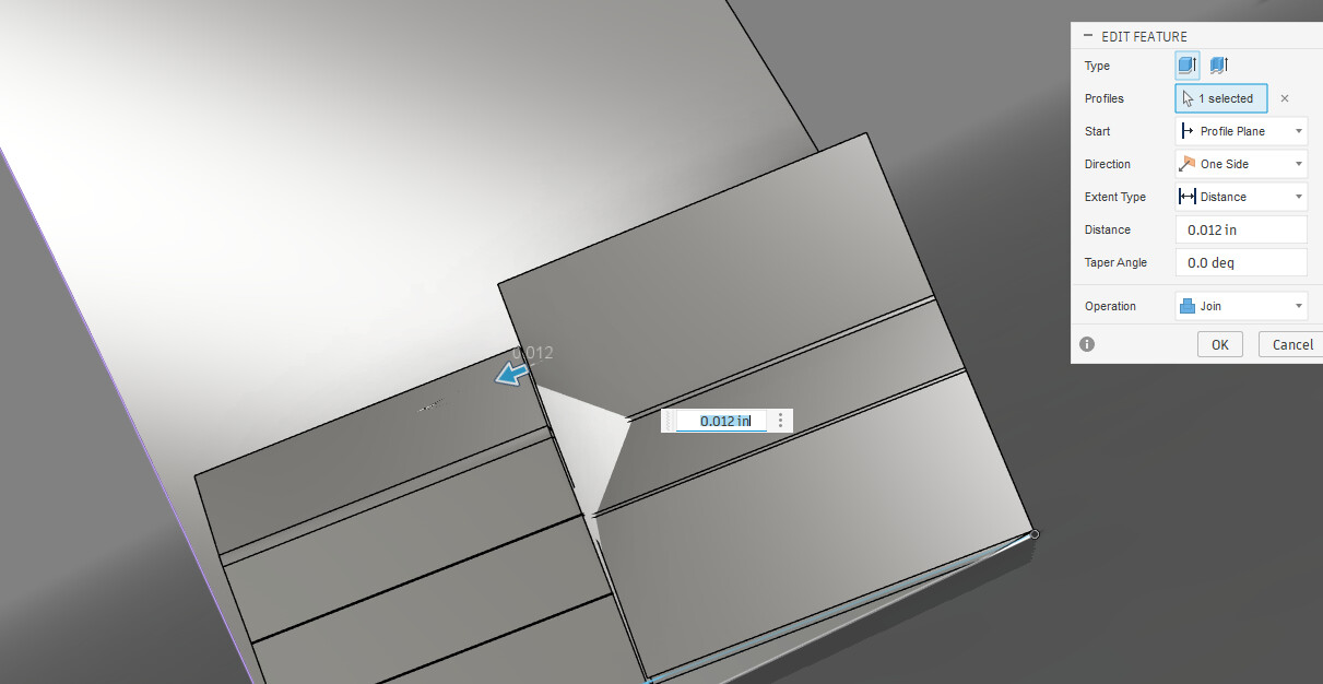
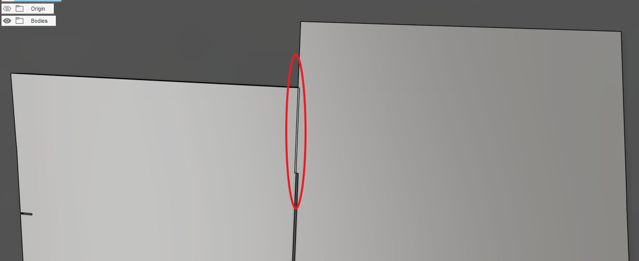
It is showing a flat panel that is increased in size but I will admit, it is a mess.

Just one more thing to rule out.
Twisted Sheet Metal surface v5.f3d (390.4 KB)
EDIT: I did that wrong. It needs to be split in the middle but I would need to make a flange off of the center (mid-point) to stretch a flange to the outer part of the fin. Maybe tomorrow I will try that. That would be the way to get a stretch realized in both directions.
1 Like
WITSEC just called, cover blown.
another way
create surface sweep

export as stl (make sure stl units are mm)
import into meshmixer (download from https://meshmixer.org/#download )
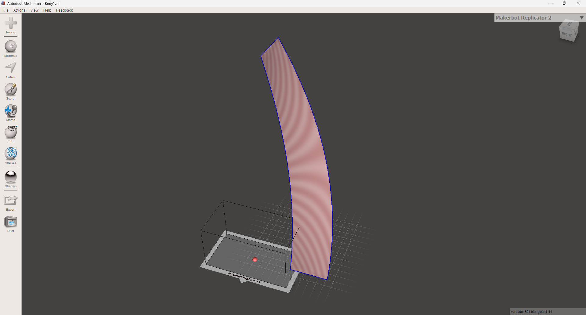
under edit, select unwrap


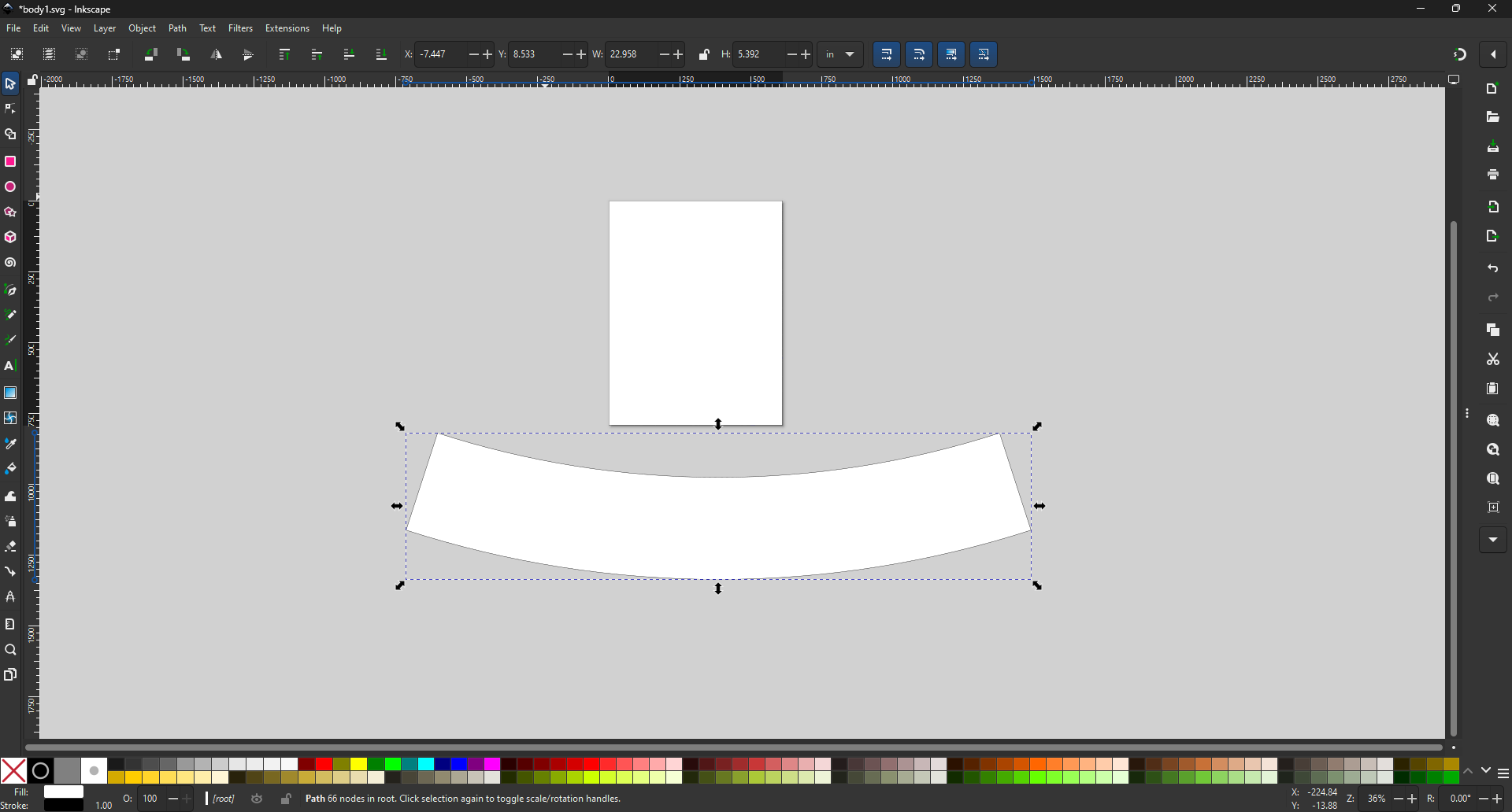
export as svg
open in inkscape to check dimensions in inkscape
I don’t know if this is any better than ways already discovered here.
Blender can do this as well for an even tricker surface.
Watch this
21:58 Mesh surface decimation - Blender Modifiers
29:10 UV Unwrap - Blender Seams
37:40 Splitting Faces - Blender Edge Subdivision
or use traditional metal shrinking and stretching skills
2 Likes
@holla2040 thanks again for the input towards this endeavour.
Now for some reason I think I need a shrinking stump in the shop, so cool.
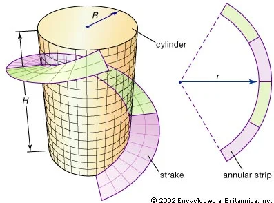
I’m not much of a mathematician, most of my geometry experience is practical and comes from being a sheet metal worker. I’ve been reading into differential geometry involved in coming up with formulas for these shapes. Along the way I’ve realized that there is some terminology that we should be using for these parts.
So the part we have been describing as a “fin” should actually be called a “strake” and the finished flat pattern sheet metal form should be referred to as “annular strip”
You may be on to something there Jimmy. Man is this a hard project. As soon as you think you’re there you try to make a flat pattern and it breaks. I have gone at this in a lot of directions. I appreciate all kicks at the can.
This is building to the next grouped topic I plan on making soon. This twist, this compound curve is just one of the baby steps towards it.
3 Likes