But could you use the spiral tool to give you guard rails and loft or surface patch from one line to another to create a patch surface and then thicken it?
I did a little YouTube surfing. I used the wrong term of “spiral”. It is “coil.”
How much of a twist do you need? Because a quick thought is lofting from two or three profiles by using a square or triangular profile, all the exact same size but on planes a set distance and you rotate the square or triangle a desired amount on each profile.
Then when you loft, you would get a nice gentle twist.
Now I am a bit over my skis on this, you would know better than me if this is even feasible, but:
Now you copy one of the side surfaces, thicken and turn into Sheet metal.
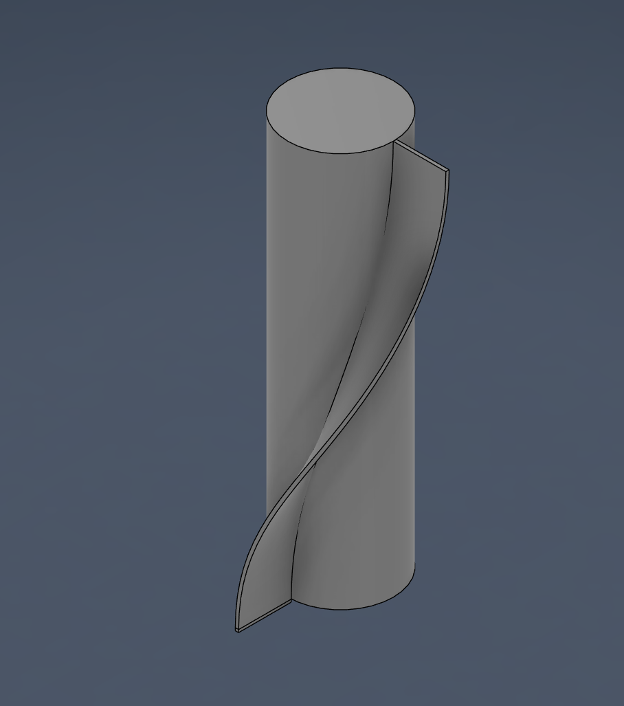
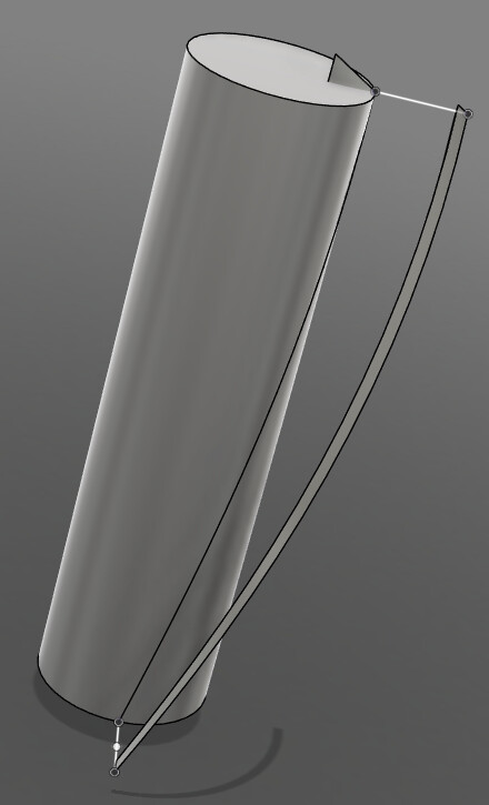
Tin, I have spent a bit of time and this and as near as I can tell - it cannot be done in fusion alone. Sure you can draw the shape easy enough…BTW I did it with surfaces using the sweep command and then thicken. Very fast and of course the surface tools are parametric so very controlled and repeatable per one of your goals.
Flattening not so much….though in my short time it appears (from multiple sources) that meshmixer does a great job… here is a video https://www.youtube.com/watch?v=dalldQLphyo
It will lengthen the tool chain just a bit, but not too bad and gets the job done. I have read that it is surprisingly accurate too (bit surprised honestly) but I would give it a shot and it may be very accurate consider this will be plasma cut I assume.
BTW I even spent a bit of time using 3d sketching and as long as the lines are straight within 3D space the sheet metal will flatten it. The environment will not flatten the complex curve. Funny enough thought this technique does work as long as it done in the 2d sketch environment like this https://www.reddit.com/r/Fusion360/comments/1bpnqn4/how_to_take_a_curved_surface_and_make_it_flat_is/ This is the trick for that “You can use the sheet metal environment to do this. You’ll have to recreate the curve with a flat section on one end using a flange. Then you can flatten it and use the flattened shape as a profile to project into a new sketch that you can then extrude back in the solid environment.“ Of course that doesn’t solve your geometry. Just thought I would share.
And I hope I am wrong and another solution appears
I’ve used mesh mixer in the past for drop cheek offsets and such I just can’t get over the idea of leaving the fusion ecosystem.
I have a method that works by using triangulation( In a 3d sketch) and then flattening in the sheet metal environment (as shown above )but it’s not a very elegant solution.
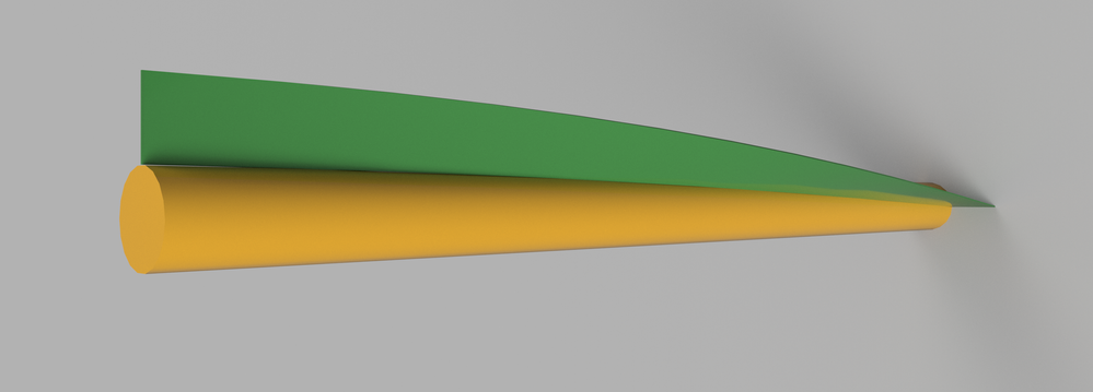
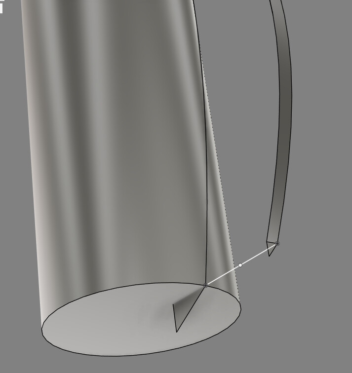
What I did was use a “3D Sketch” to make the inner and out rail of the twist to create a Surface using “Loft”. Once the Surface is created used “Thicken” with the same thickness as the intended sheet metal rule. Once that is done, I “Extrude” the bottom face down 0.01” to give a flat section for Fusion to “Convert to Sheet Metal” and to give it a spot to use to “Unfold”. The extra flat section could probably be 0.001” just to give a flat spot and not affect the part much.
I’m not 100% sure Fusion understands the unfold correctly, would need to cut the part out to test it but this proof of concept seems to work.
Tin’s Fin.f3d (64.0 KB) Here is the file you asked for.
BTW Welcome Muddr I hope your first post is only the beginning…great stuff.
Couple things I noticed between Muddr and my technique…mine is faster but has some problems, mainly that the ends of the sweep are not in the same plane as the cylinder ends. The sweep obviously makes it normal to that plane of the cylinder end. Better, more cuttable, and truer to the end design IMO.
Secondly, I learned that there is a “convert to sheet metal” command….who knew…I have worked a fair bit in the sheet metal space but always started from a sheet metal “component” then a sketch of the base flange, turn the sketch into flange and build from there. Cool.
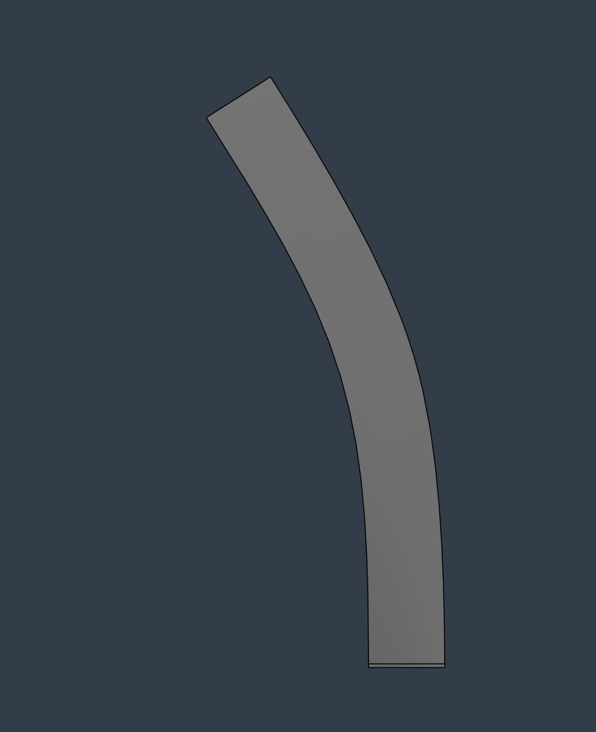
Lastly and I don’t know where this fits Tin’s goals, but there is big differences between flat patterns and unfold(s) the latter Muddr used. I did create a flat pattern out of Muddr’s file so it is available in the machining space.
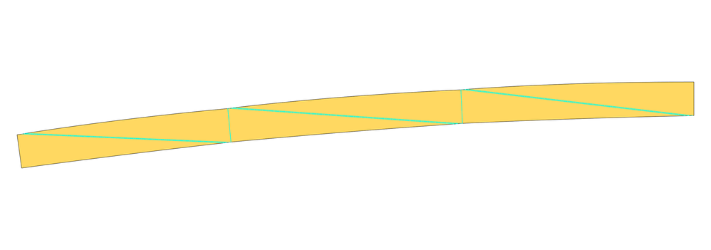
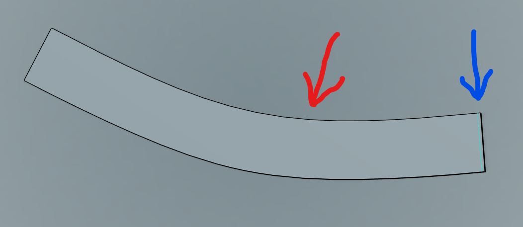
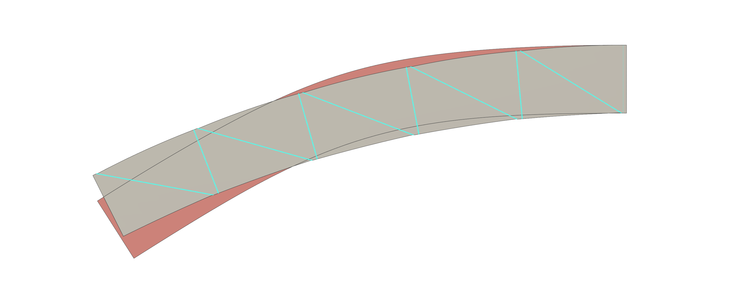
I do have a question about the unfolded/flat pattern outcome, do you all think it really looks that? In my mind I see the need for added length, to go around the cylinder, but I don’t know for sure whether it needs the arch in it. Thoughts?
The pic is from Muddr’s file but the flat pattern I created in it. The Blue points to the base flange the Red is the arch I ask about.
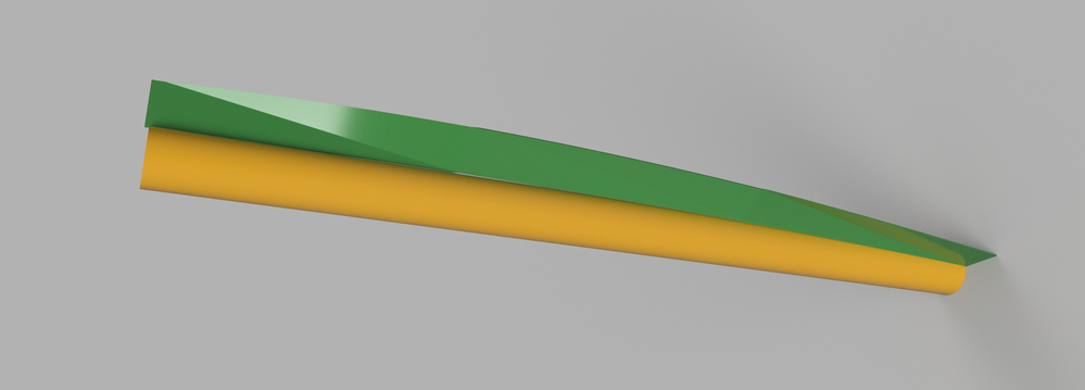
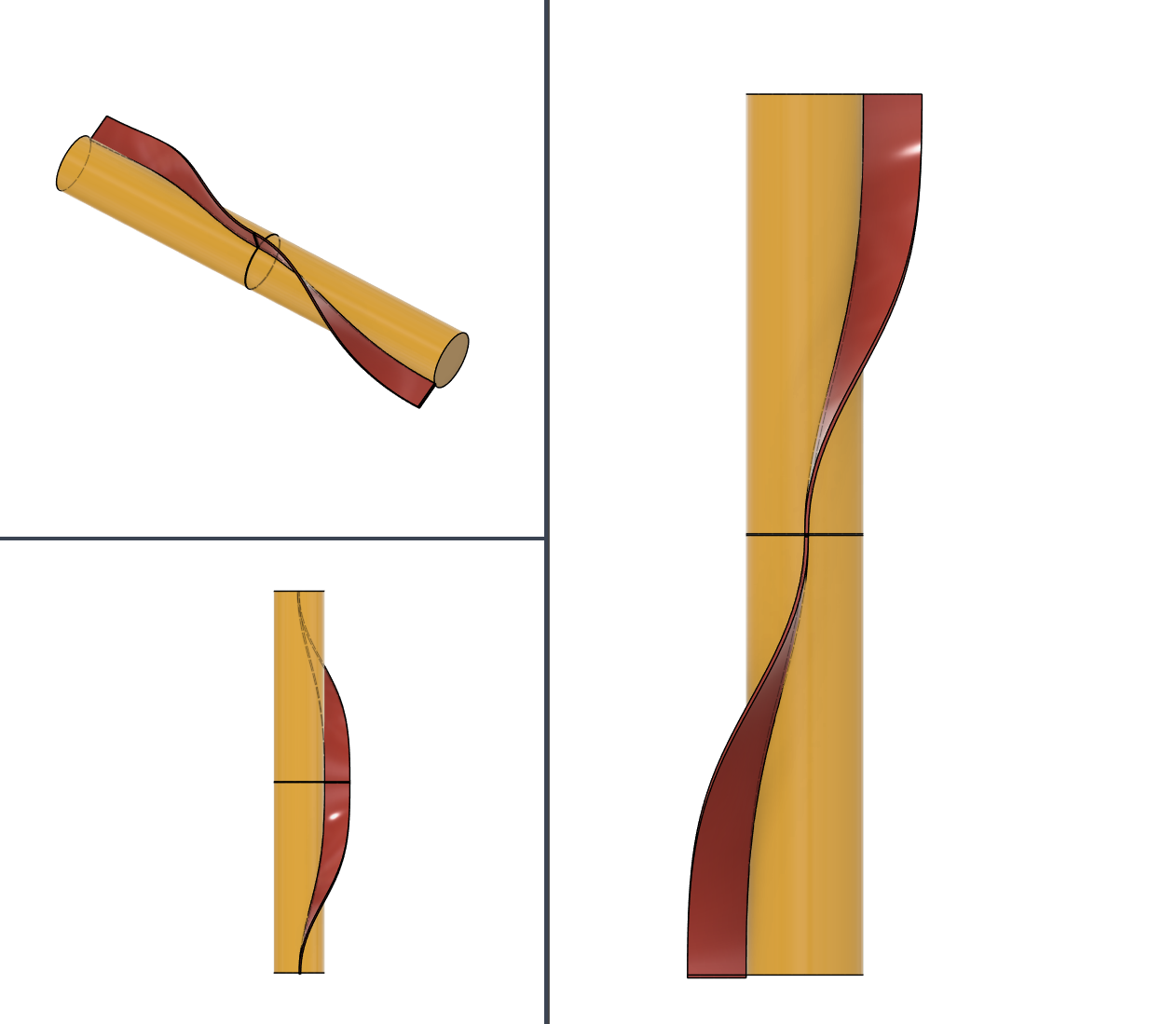
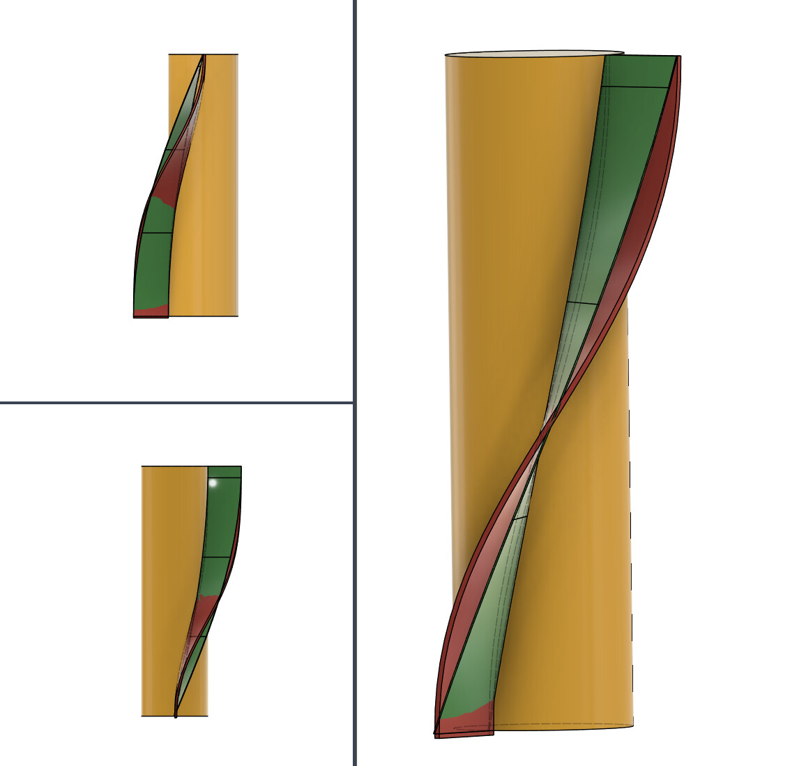
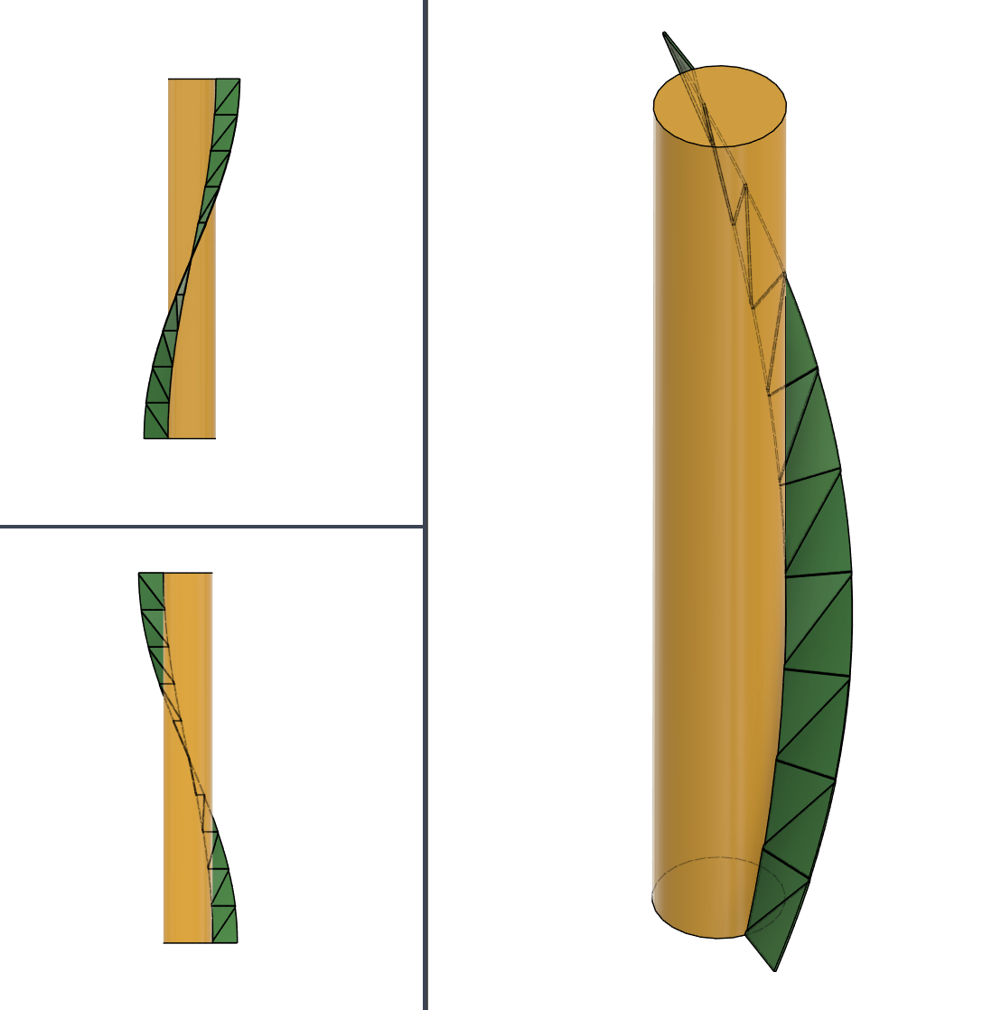
@Muddr thanks again for taking the time to post this. I had some time this morning to start dissecting this. I love the simple workflow. The only problem I have with it is that the shape is not a geometrically correct twist/coil. I’ve stacked two of your examples on top of each other and I think this really highlights the issue with this geometry. I also superimposed a geometrically correct twist/ coil it’s on top of the one you presented.
Also loving all this collaboration i feel we’re getting close
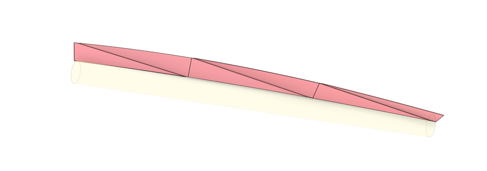
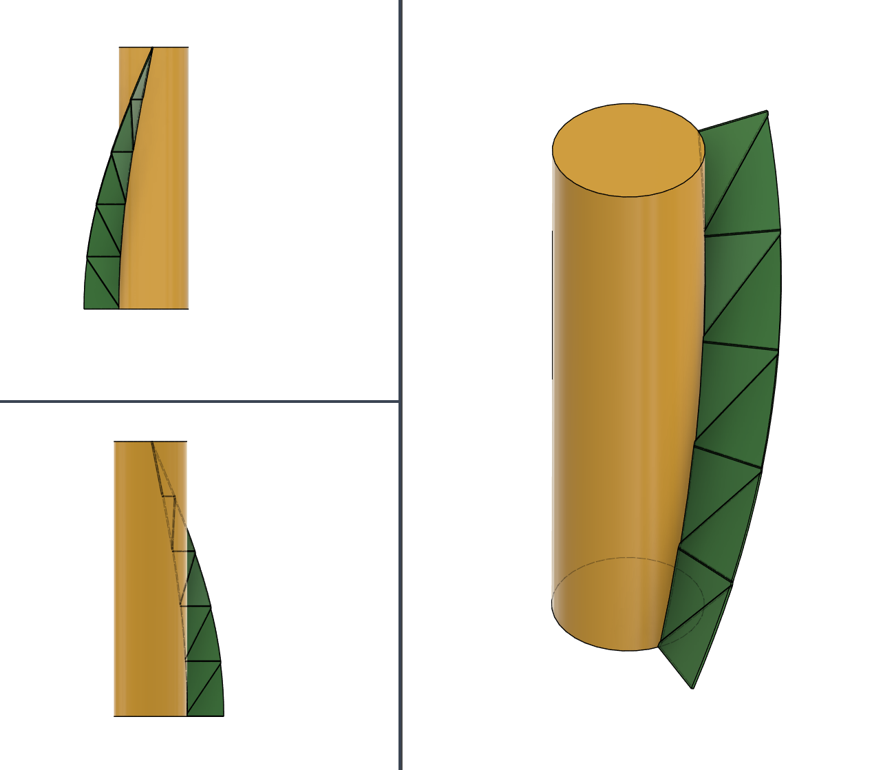
Here’s an example with the methodology I’ve been using which is a form of triangulation.
recreated it with the same height(15”), cylinder size(4’” dia), rotation(.25) and fin length(2”) as @Muddr ‘s example so we can compare results easier.
It’s also the same methodology I posted on the Autodesk forum looking for ideas which has not incredibly fruitful yet.
I did get a couple interesting methods there but they did not conform to my requirements listed above.
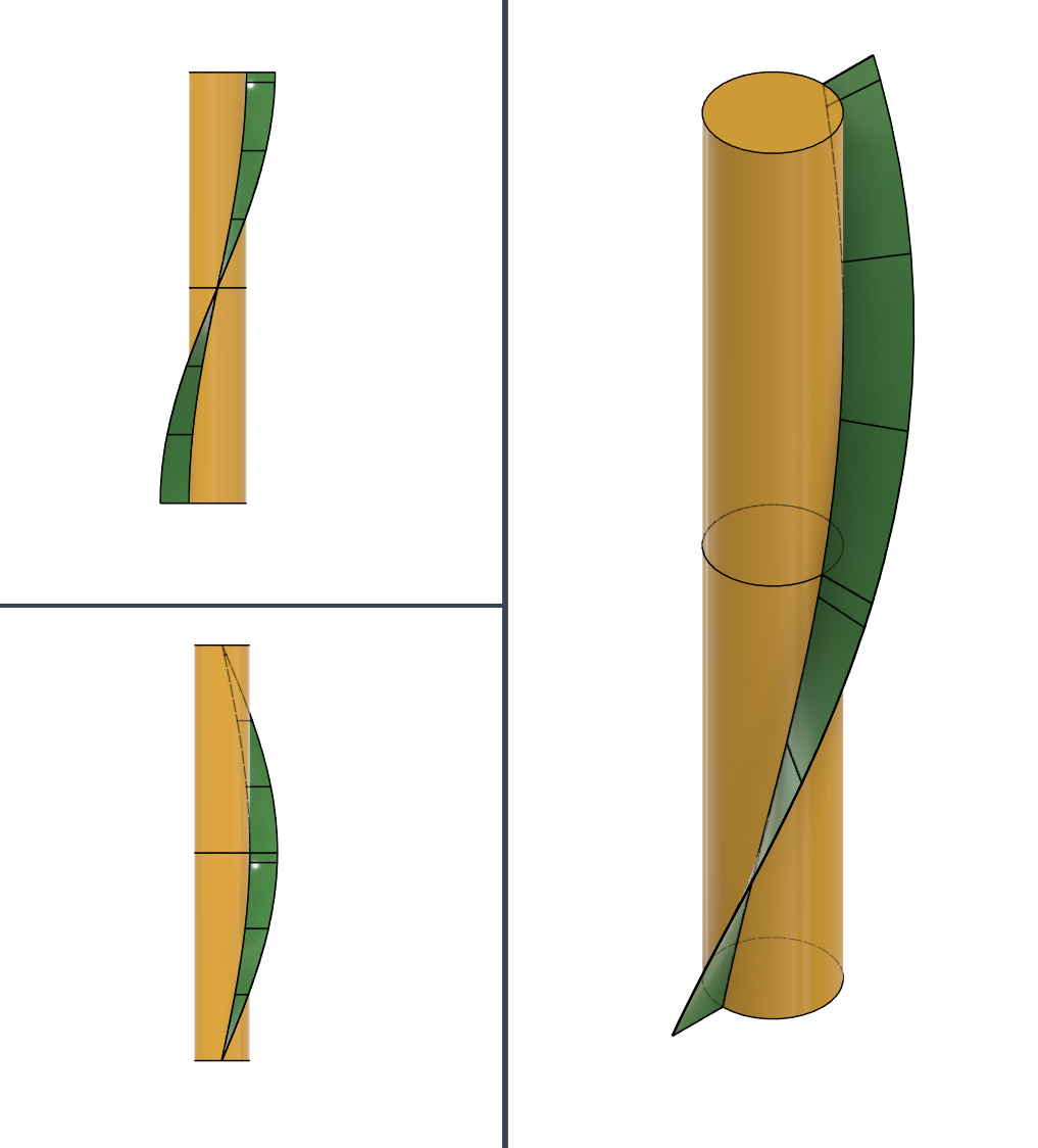
Here’s also a picture of 1 stacked on another. This is an important point you should be able to stack as many of these on top of each other without any odd geometry.
I then added the coil at 8 inches to get 2 inch distance between the edge of the triangular coil. Add a line to connect both coils and the surface creation is easily done.
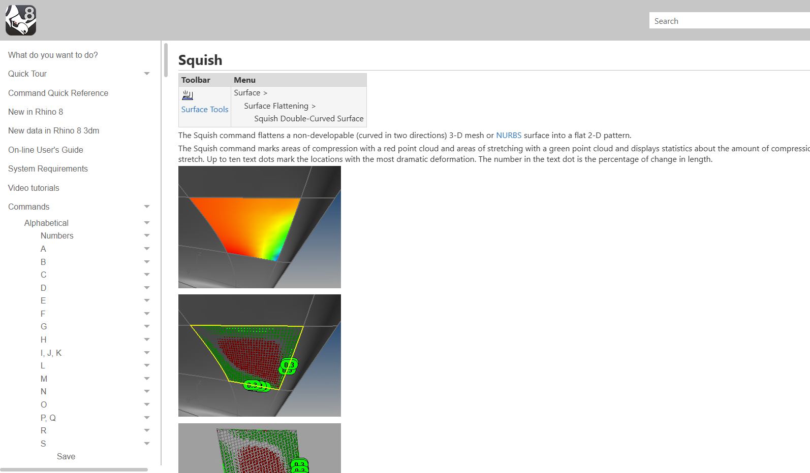
But I can’t flatten it. So my efforts are useless but I did bring one piece of news, perhaps. There is a software that says it can flatten a surface with a squish tool:
The software is free to use for 90 days but I am a slow learning and can’t seem to get a result. Maybe one of you have another idea. Tin, I know your heart is set on staying in the Fusion environment. Perhaps it is possible. Craig (@holla2040 ) probably knows a way but he is keeping it to himself until we are all in tears.
I have a theory of why Fusion is staying away from the Squish or Smash tools as there is a form of guessing/generalization with the transition. Even the Rhino programs calls it an “approximation.”