I took a somewhat different approach to building my mill, and I wanted to share the results. I will publish some deeper info into the casting process and final photos later on, but for now here are some build process photos. And in order to sprinkle a small amount of precision machine tool magic, I’ve given it an oversized name in german, Die Hochleistungs Werkbank.
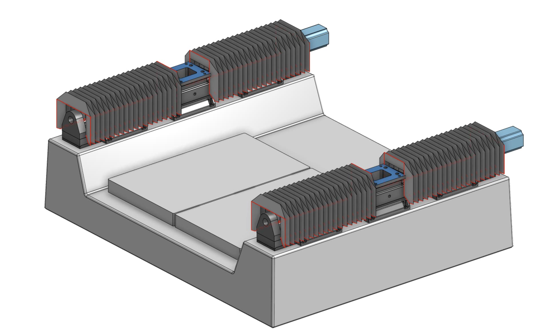
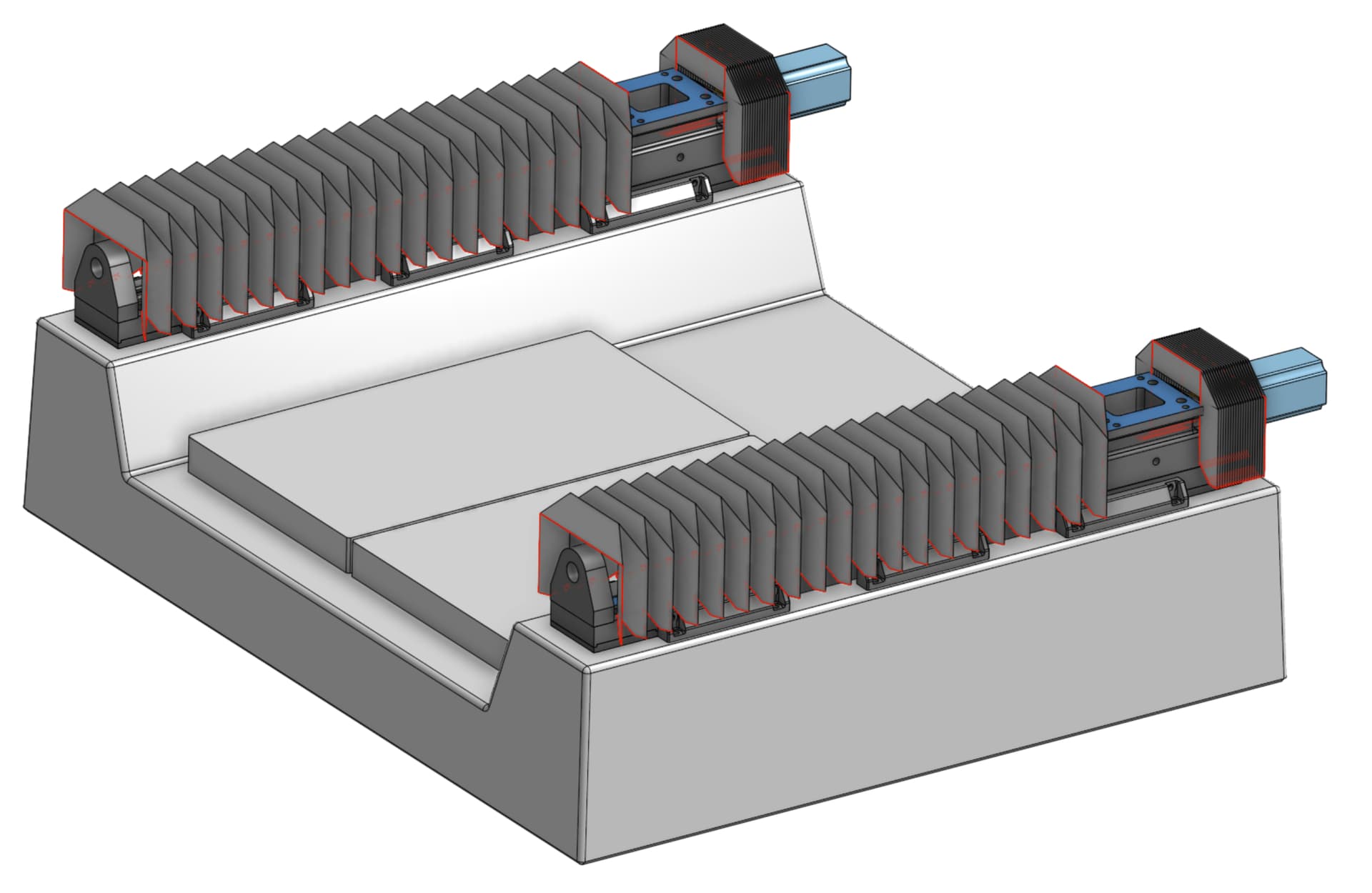
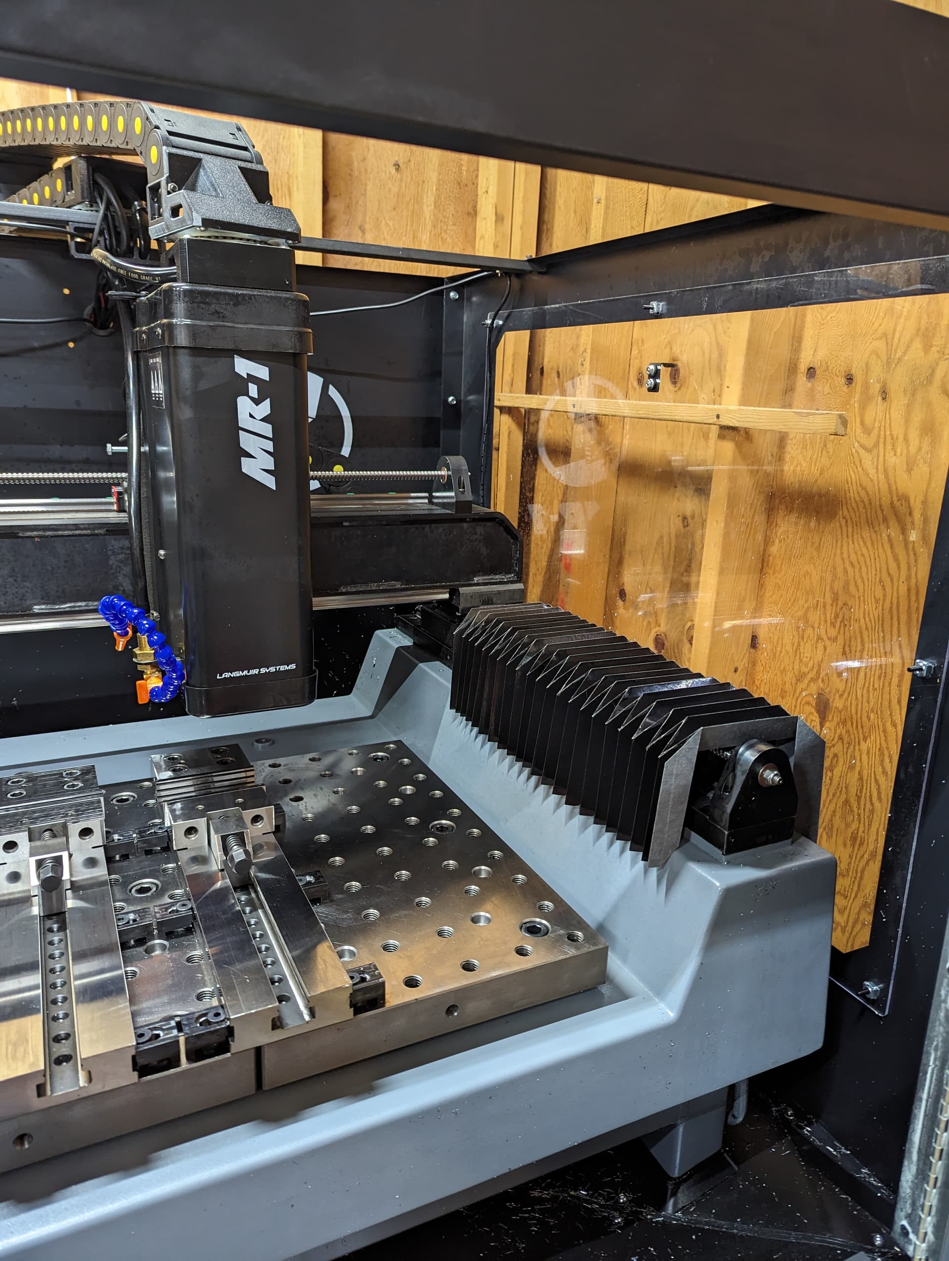
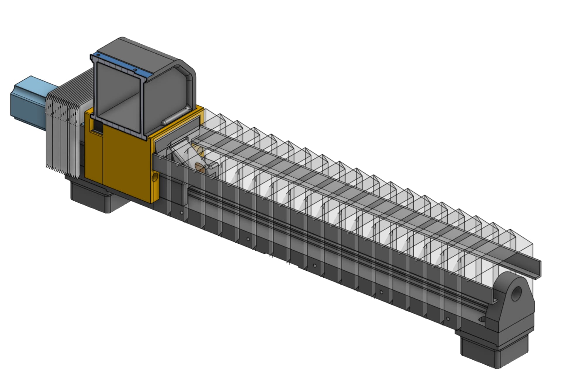
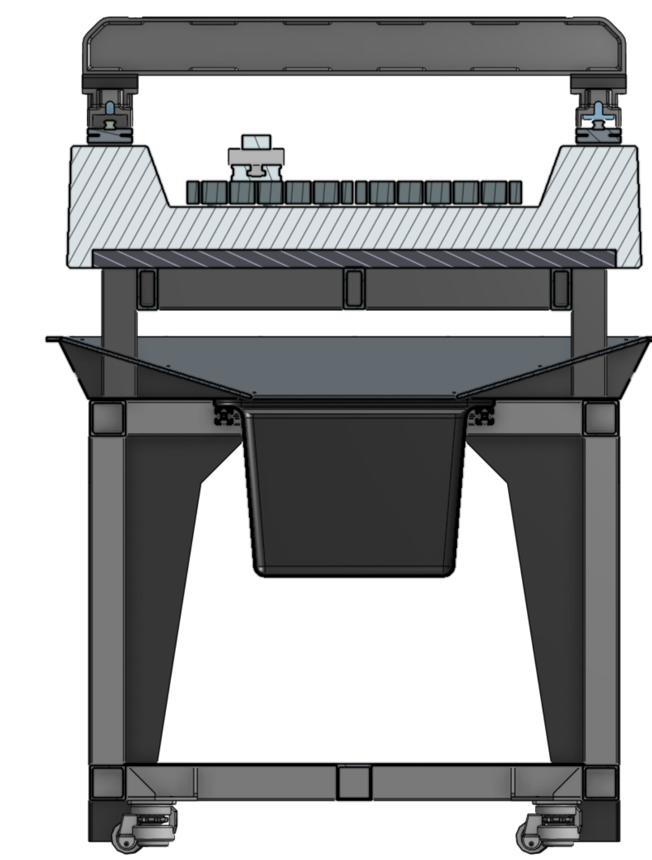
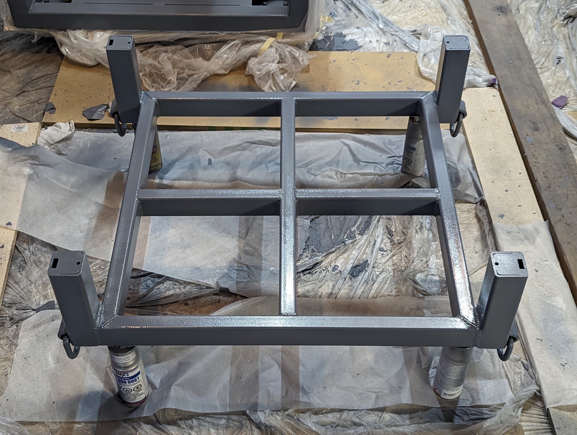
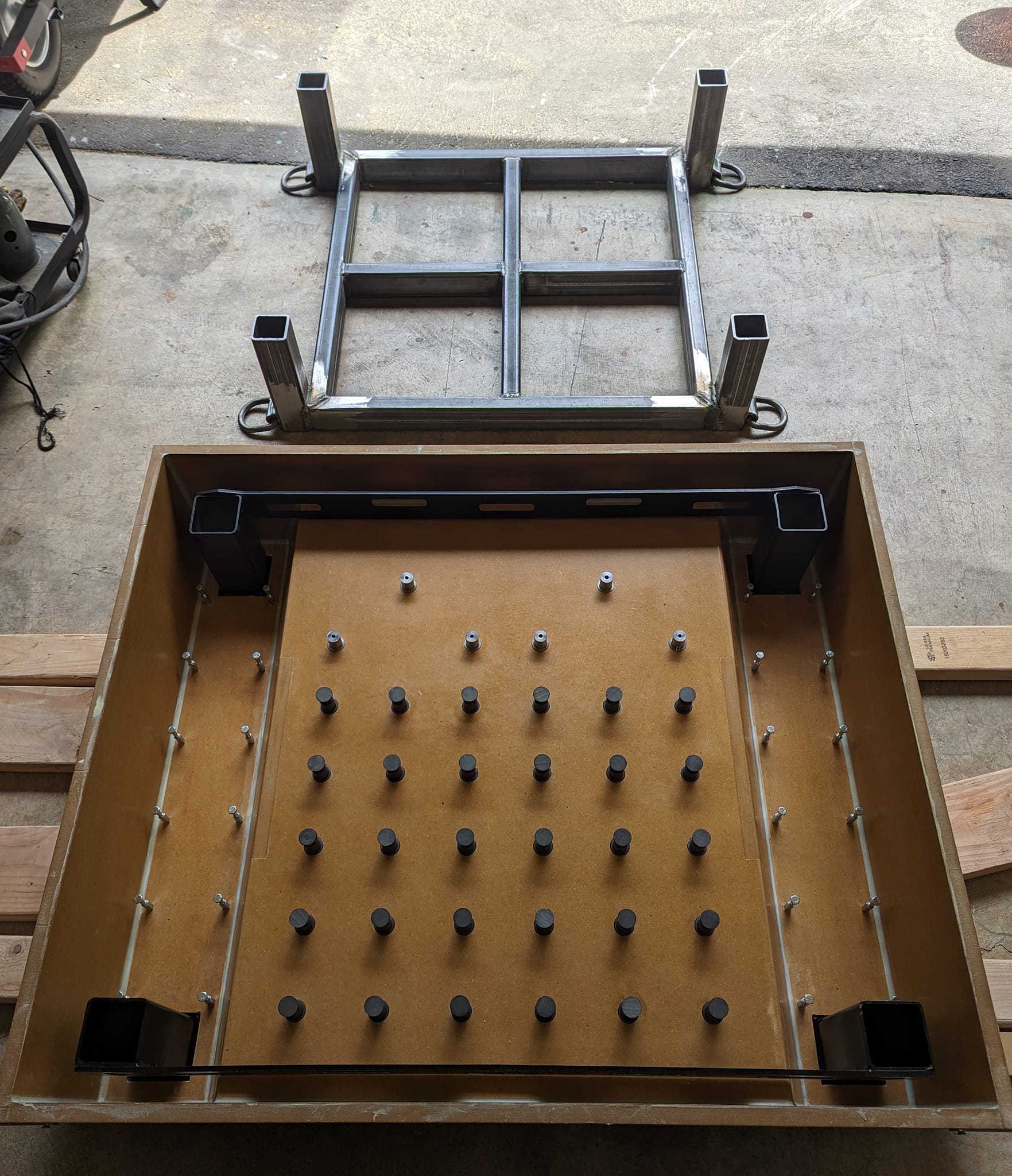
This machine has no drains- the whole table hovers above the chip bin like a Datron. I also built a new frame from welded 1/4 inch wall square tube. The fixture plates are 40mm thick, stress relieved cast iron, and are removable for fixturing directly to the machine bed if needed.
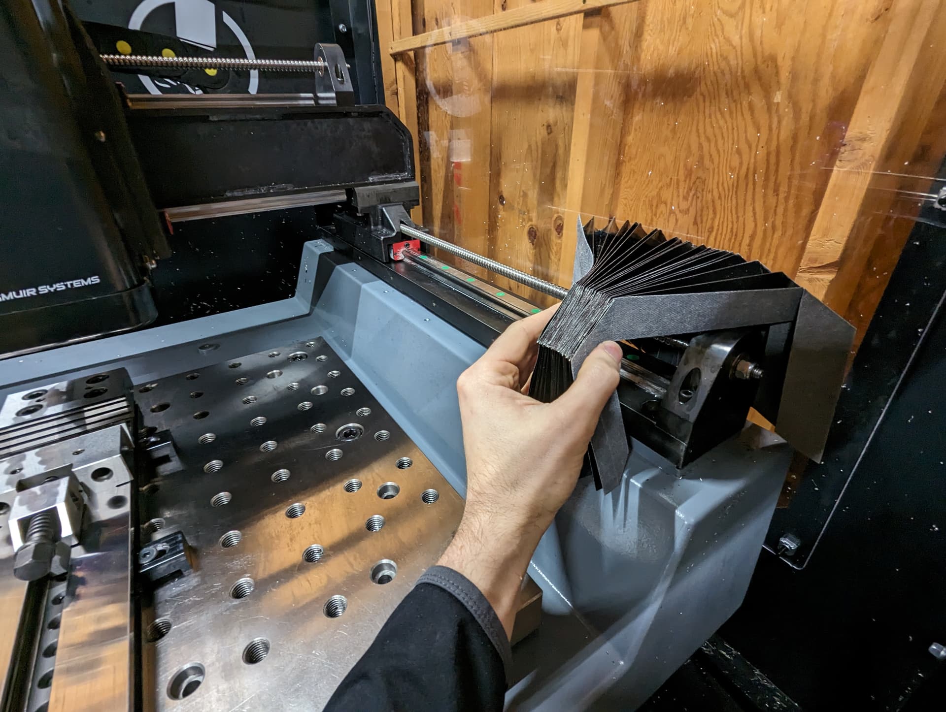
Just need to put on the enclosure and finish sealing up the flood coolant system. There will be a 5 gal sump below the chip bin and in-line filtration.
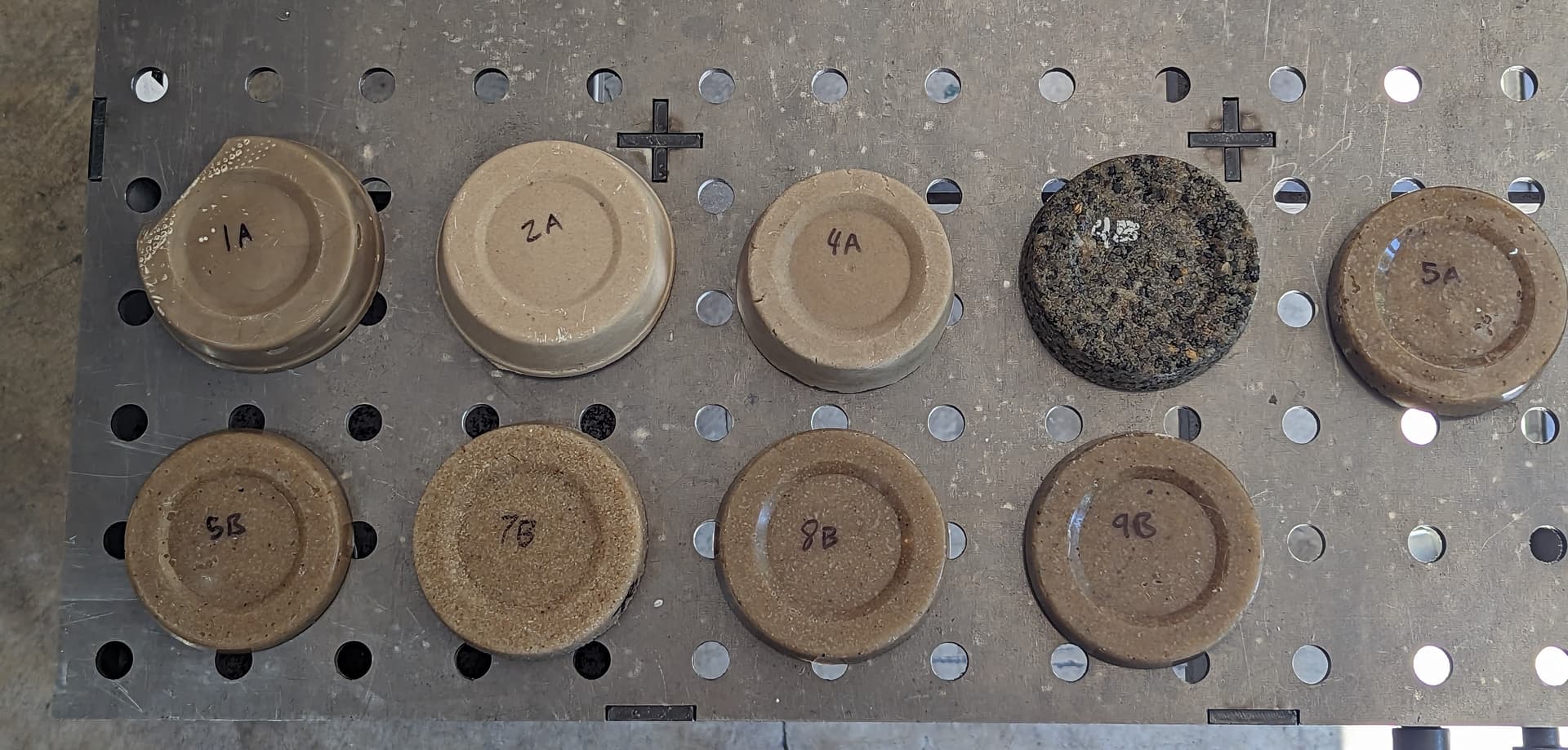
The mold with Bondo fillets, waxed and ready for fill. NOTE: if I did this again, I would use melamine board rather than MDF. Even with extensive waxing and a good amount of draft, it was a challenge to demold. The epoxy granite slurry is extremely abrasive, and easily wears through the wax barrier. This wouldn’t be a problem with melamine laminate board. The only reason I used MDF was because I already had it laying around.
The finished machine bed after demolding. Originally I was planning to leave it black, but ultimately I decided to give it a coat of Raptor epoxy primer (grey) and some 2k gloss topcoat - it’s easier to see dropped fasteners against a lighter grey.
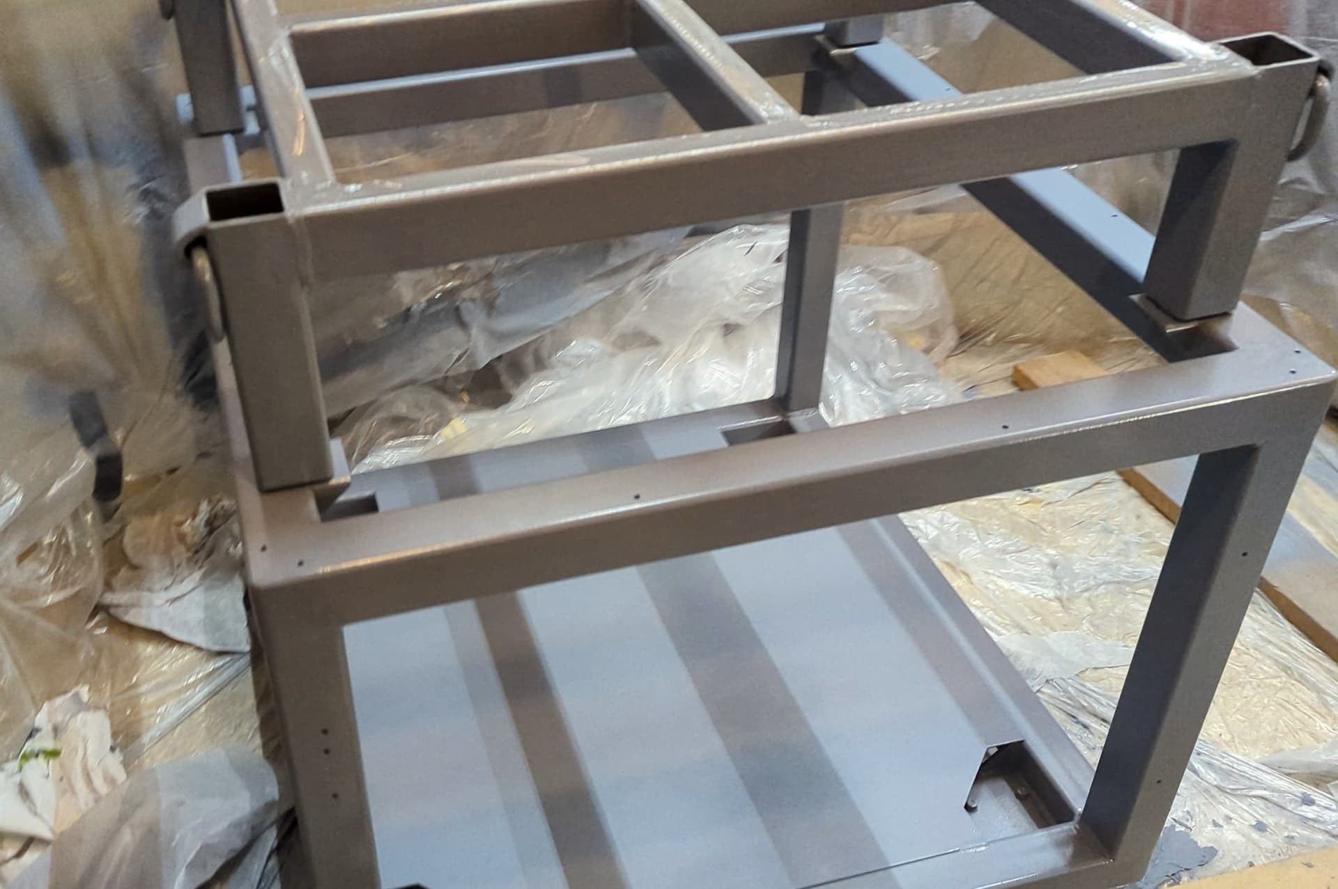
Here’s the subframe and base frame stack up bolted together. The original sheet metal legs provide some extra stability, as well as some extra vibration support when the levelling feet are deployed, so that all the load isn’t on the levelling casters.
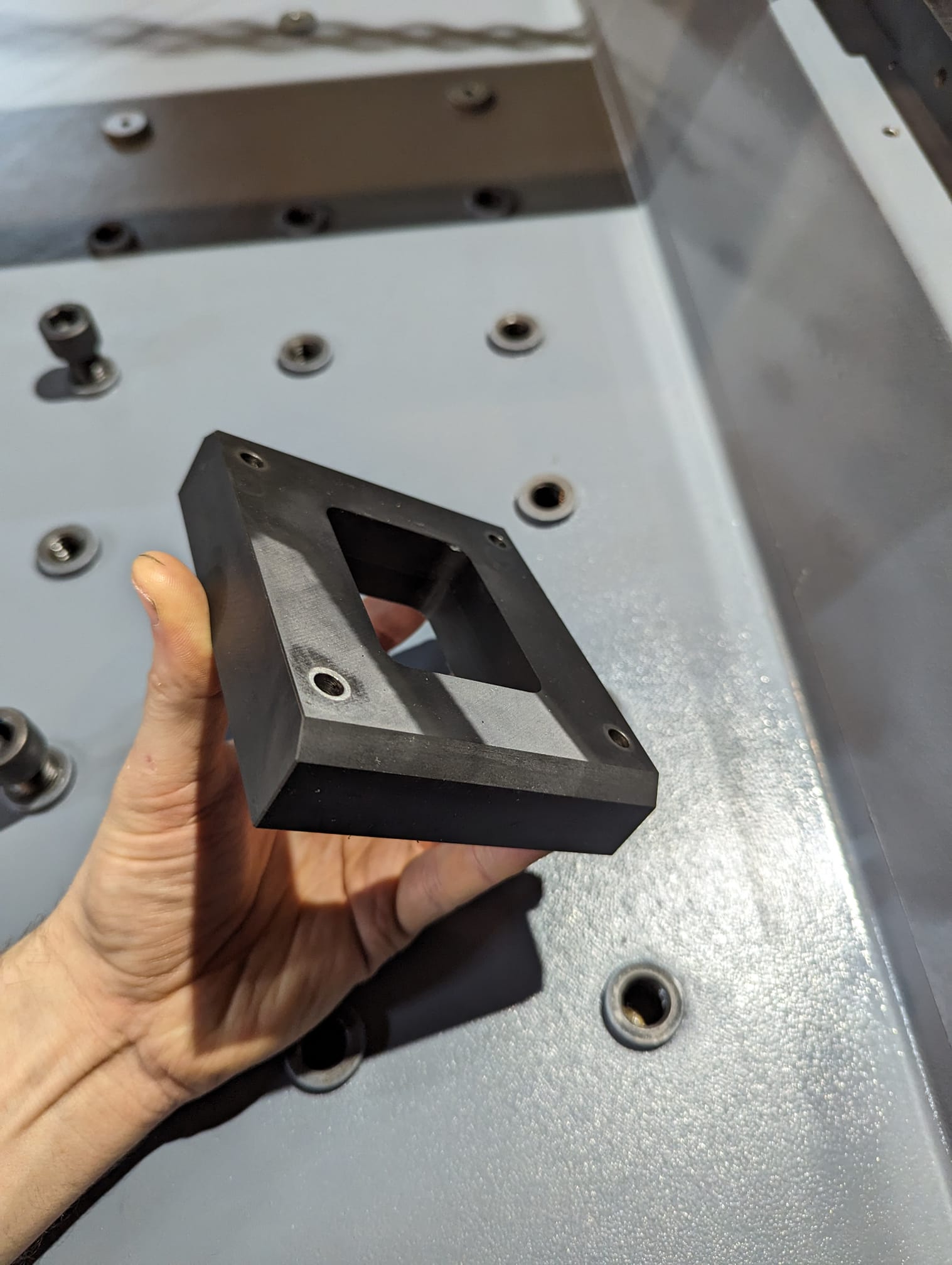
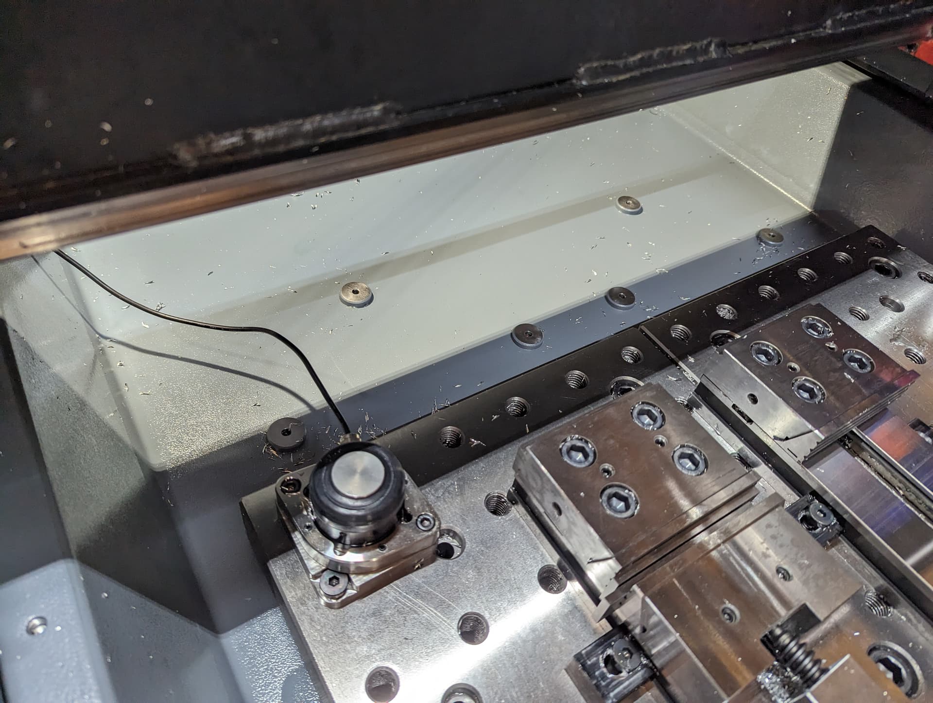
Here’s a spread of the more interesting epoxy
granite formulations I went through. Ultimately I was optimizing for:
*Volume fraction of filler, in order to control thermal expansion difference between embedded/bonded steel components and the casting.
*high Mixability. This is only viable if it can be mixed in garage shop conditions, which meant a 3.5 cf cement mixer.
I used the rule of mixtures as a rough proxy to estimate thermal expansion of the EG casting. At ~20 vol% epoxy (15.5% massfrac) the mixture should have a linear CTE of around 12 (10^-6 m/m°K). That also happens to be right around the lower limit of where I could reasonably mix large quantities of EG, since viscosity increases in a non-linear manner with increasing filler.
.
The final formulation was as follows (percentages are of total dry fillers by weight):
Fillers:
5.5 % Fines - made of 5% Sil-Co-Sil #45, with a D50 of approx 21µm, and 0.5% Fe3O4 powder.
21.5% Semi-fines - Lane Mountain LM125 Silica Sand, with a calculated D50 of 99µm
73% LM30 Silica Sand, with a calculated D50 of 696µm.
Binder:
15.5% Mas Deep Pour Epoxy, which has great (unmodified) strength and decently rigid elastic modulus.
The Mas Deep Pour epoxy TDS states a flexural strength of 13,480 PSI and compressive strength of 11,260 PSI. Just as important however, is that it has an extremely low mixed viscosity (260 centipoise, like a thin syrup). I attempted to use a higher viscosity epoxy system (Promarine), and it had unacceptably high viscosity. If I were to re-do this, I would choose Mas Deep Pour X - I think the slight sacrifice on mechanical properties and viscosity are counteracted by the benefits of being able to stage the epoxy pour over several days. With the Deep Pour standard formulation, I needed to pour sequential mixes within about 4 hours of each other to avoid laminar discontinuities. Exhausting!
Another note - adding fines to the mixed epoxy, fully mixing them together, and only then adding coarse and semi-fines resulted in a MUCH easier to mix slurry, vs attempting to mix coarse in first. Coarser particles seemed to have a much greater impact on viscosity than fine particles, up to a point.
Great Work! Gives me the vibes as the Adam Bender machine floating around on Hackaday.
A couple of questions.
Did you add that Y axis spacer to gain back Z space from the extra thick fixture plates? Or do you plan on reworking the Z axis stage to get more overall Z workspace?
Do you have more details on those cast in thread bungs? Custom machine or OTS part?
Will the enclosure still fit? It looks like it!
Other the chase of machine tool perfection. Were specific needs that forced you make these changes?
You’re correct, the Y axis spacer only gets me back the space I lose from the extra thick fixture plates. I intend to machine similar risers for under the Y rail beams (at each of the 4 corners), but these will be made on the MR-1 itself. I figured it would be easier to make 2 to start than 4.
Yes - there are a few types, all custom. I turned the ones at the back (with 1/4-20 threads) out of 304 stainless round stock. I gave up on this because it was taking too long. The ones in below the fixture plates have 5/8ths internal threads, I’m not great on a manual lathe, so I didn’t want to turn the internal threads. Instead, I made those out of these probably mild steel weld bungs: AA-138-J Steel Weld on Nut, 7/8" Long, 5/8" - 11 Right Hand Thread - A&A Manufacturing
I threaded partially threaded on some 5/8ths bolts from the underside, tack welded them together, and then sand blasted and parkerized the lot for a bit more corrosion resist.
Yes - just need to finish caulking and sealing!
Forced? No… but the main goals were to make a machine with these major traits:
High resistance to freeze-thaw thermal cycling, in my currently un-heated garage. As they say, it’s not a question of whether concrete will crack, but rather when. EG should be much better.
Mobile and transportable: the original design is hardly mobile, and the sheet metal legs don’t inspire confidence that I could have put it on a trailer and moved with the machine without any damage. The rigid subframe lets me roll the mill around the shop with less likelihood of losing calibration.
Better cleaning workflow. I wanted to be able to wash down the machine with a hose and nothing else, and deal with chips out of the chip bin later. Drains on the original table design seem like a very annoying feature. Someone made a chip auger- that’s a step in the right direction as well!
I know my own habits pretty well. If I have to do a laborious clean up process involving vacuuming and sweeping after every job, I simply won’t. And then it’s left there, as an annoying barrier to starting up working with the machine next time.
Yes - accordion style rail covers will be imminent. Later on I’d like to swap to closed loop servos and an ATC spindle. The anchors at the rear are intended as mounting points for a future ATC magazine.
Superb results and thanks for sharing! Hell of a job! While a MR1 is currently out of range for me, a small semi-cheap chattery manual machine has been in the back of my mind for a while. This is great info!
I’ve heard of people filling the column of a low cost manual mill with EG for better damping. I’d definitely consider doing that on a mini lathe - although the epoxy alone in this project cost as much as a China mini lathe.
There’s quite a lot of hollow space in the underside of those mini lathe castings. Its one of the reasons they are floppy. I wouldn’t follow the process in that video exactly though.
I plan on laser cutting, folding and gluing the first prototype of these, but I also did reach out to a couple of chinese CMs and got quoted about $250 for a single set. Really not too bad. The price could come down if some people wanted to do a group buy. I see no reason why these couldn’t be made compatible with the stock MR-1 as well.
Still need to design the endcaps, attachment points, and the surfaces they will slide on. Will probably 3D print those from PET to start.
The X axis is giving me a little more trouble. The top rail and screw are better protected by default already sitting on the back of the gantry beam. The bottom rail could be protected by a roll-spring type cover or an air curtain … although TBD if it actually gets pelted with chips.
What are the dimensions of your table? It looks like you might have left over Y travel to put a tool changer rack well behind the table and get some more Z distance for tools to hang into.