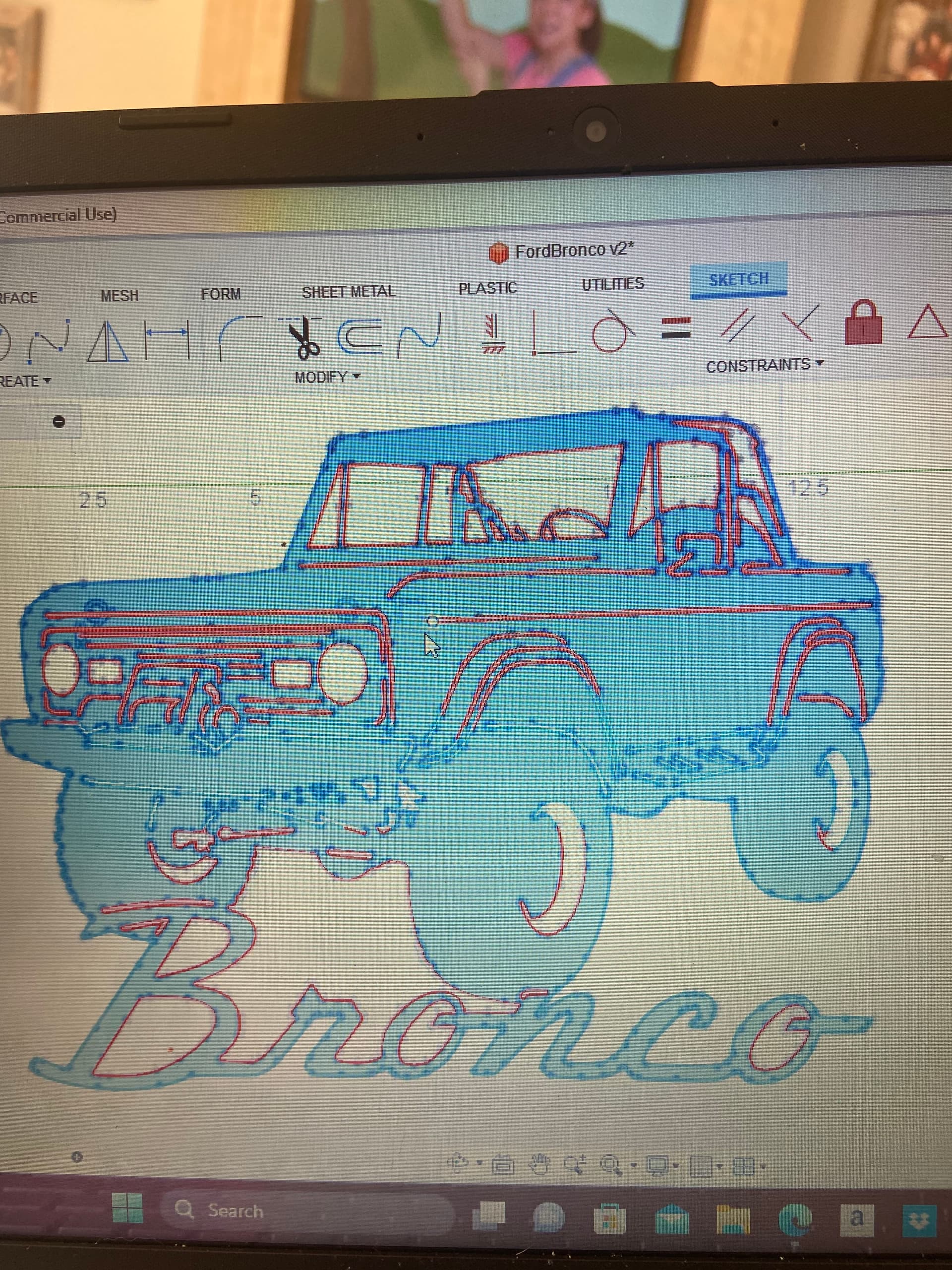
I can’t get fusion 360 to create a tool path to cut the fine lines on this design. I’ve set the kerf small as possible zero’d out my lead in/out and changed my settings to “center”. This is all info I have gathered from the forum and internet. There is something I’m missing or just going at this entirely wrong. I am new to program and plasma cnc. Any help would be appreciated. I’m running the RZR cut 45 with the crossfire table, Fusion 360.
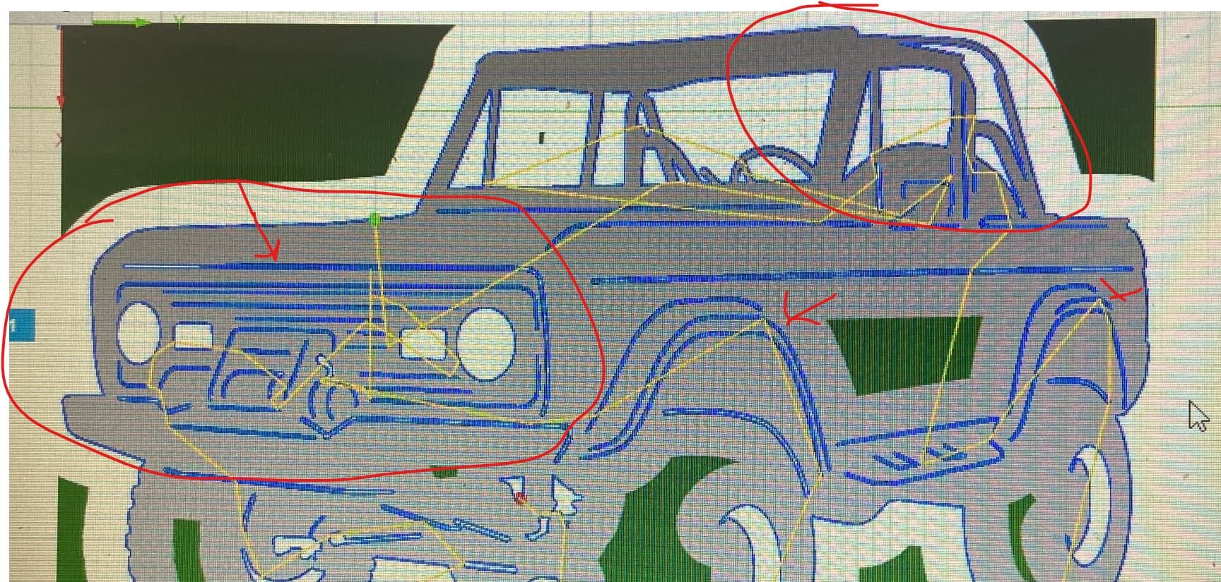
Being that I’m a new user the forum won’t let me upload a dxf document but here is a photo
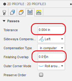
You can also get a lot of detail by decreasing the tolerance from 0.0004 to 0.004. You might consider putting a “Finishing overlap” of “0.01”. That will help improve your cut based on what I will suggest in the next slide on lead-ins and lead-outs.
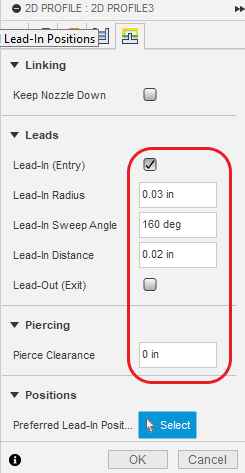
For even more detail this will squeeze more out at some expense with the lead ins. For most all cases, remove lead-outs and definitely set “Pierce clearance” to 0.0 nearly ALWAYS!
And if that doesn’t get everything you want, remove the Lead-in. Of course that will jeopardize some of the quality of the cut. (And put extra wear and tear on your consumables.)
The order I take is to see what I can get with the slightly more conservative whittling down the lead-ins. Let that be your last toolpath. See what you did not capture and then add an additional tool path where you select the contours that the first tool path failed to catch. On this tool path remove the lead-in and set pierce clearance to 0. This tool path, you will move into first path on the path to cut.
Always set pierce clearance to 0. You don’t need any pierce clearance, ever. But you will gradually see that you do need some lead-ins and finishing overlaps as you get better with things.
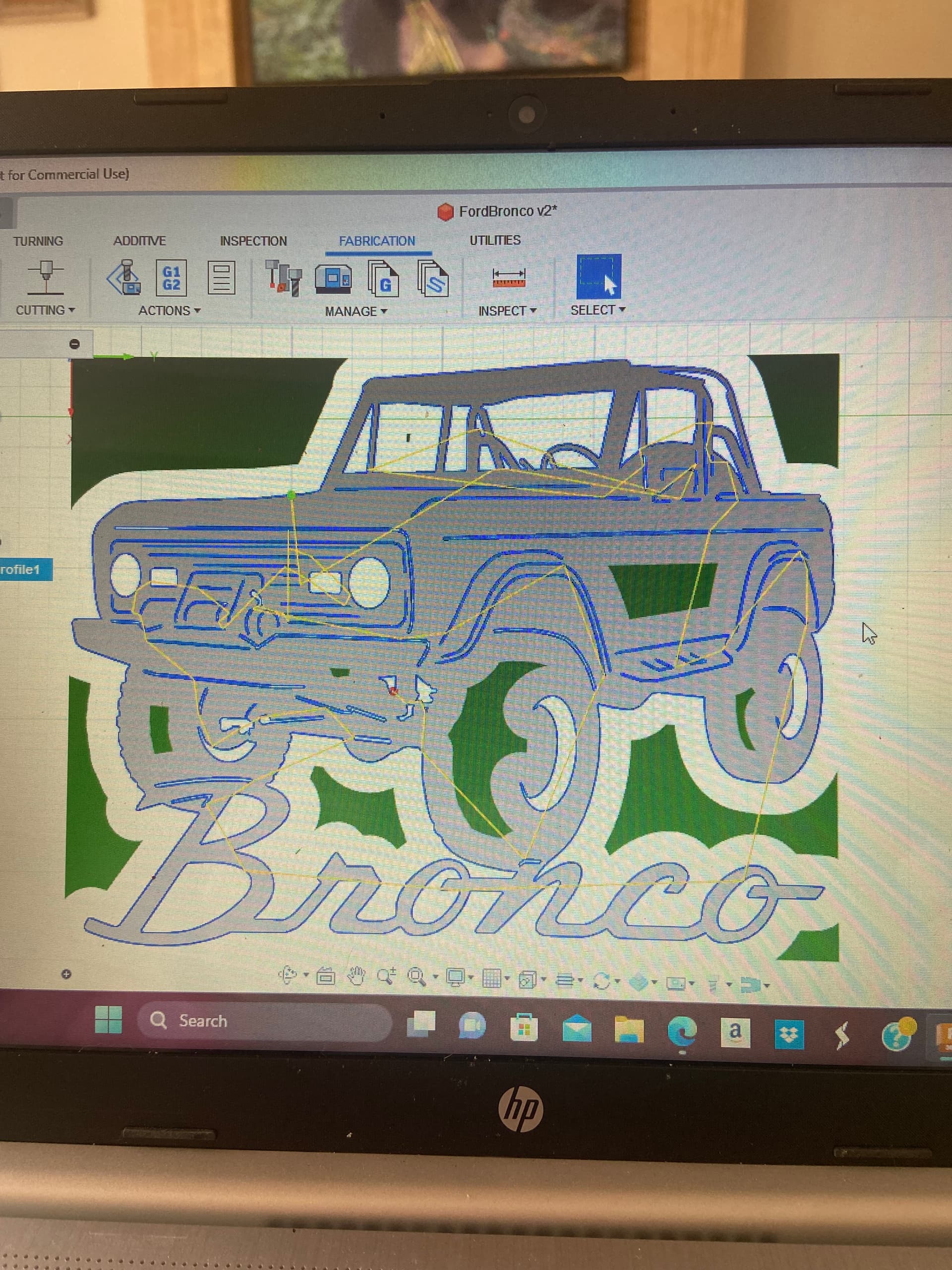
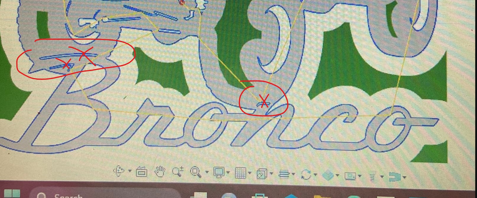
Be careful…just because the tool path is green don’t mean it’ll cut good. I would personally change a few things like the small loops to single lines and remove some of the really close lines. I might have time this afternoon if you figure out how to post dxf. I can make it more cuttable. Are you using fine cut tip?
You can always look at the places it won’t cut and measure those spots and see how small they are.
How big is that design? You can always try scaling it larger.
Thank you for all this information. This is what I have been needing. Im going to see what your settings will allow me to get away with. I plan on cutting this today.
The current design is scaled at 12" (W) 10" (H) it be nice to scale it larger but at the same time I’m just trying to make a test run before using large amounts of material. So are you thinking this is to much detail for this small scale?
I did that process before I tried setting my pierce clearance to zero as DonP suggested. Tried everything I know of. Process of elimination. The current size is 12"(W) x 10" (H) I just wanted to make a test run before possible wasting larger amounts of material.
The forum says I’m to new of a user to upload a DXF file. Not sure if you know of a work around for this, but Id love to see your take on this. Thats a great way for me to learn on future projects on the do’s and don’ts on CAD drawings for plasma.
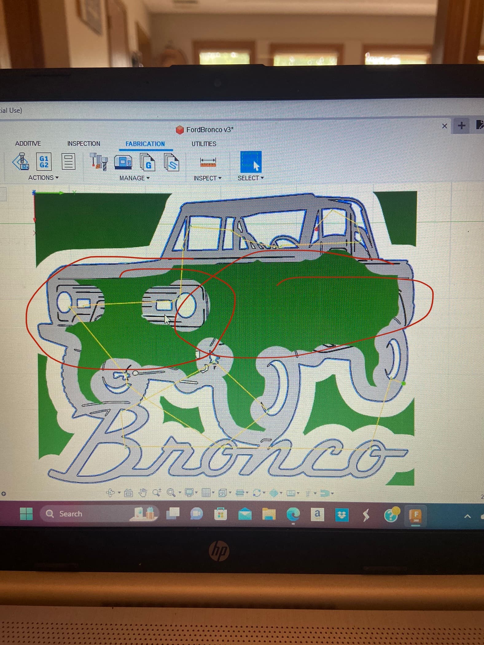
@ChelanJim with the settings you suggested it did not generate the entire tool path. It left out the grill and side detail. With the lead in removed and set to “center” it does generate all tool paths. Should I remove detail giving the size? 12"(W)x10"(H)
That means the lines are so close together that they are not finding enough material to burn.
It is like @DonP was saying. If the lines are closer than about 150% of you kerf width, they might not survive and you are better off making this a single line cut which is basically removing half of the contour lines of that contour or making your own line down the center. You then make a tool path that will only cut your single line elements with the center compensation, no lead in and no lead out. Move this tool path to the first cutting position.
So all of the elements that is not being captured without the center compensation, you will be best off treating it in this manner.
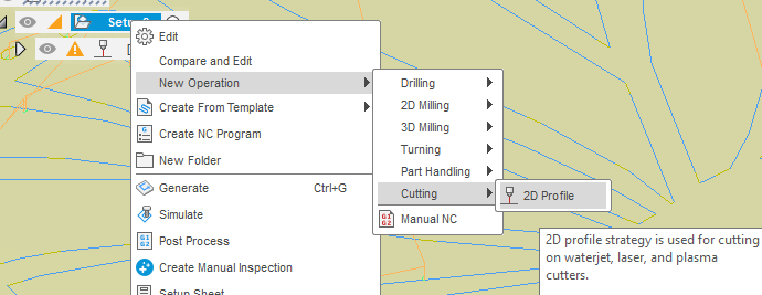
If you need help with the additional tool path, it is actually pretty easy. While highlighting your set-up proflie, right click on it and you will bring up these options:
You must be sure to move your single line cuts into the first position of the tool paths otherwise the other toolpath will cut out the outside of the object and you will lose the accuracy and possibly the electrical connection to the piece of metal.