Maleybr,
Thanks for the tip! You, my friend, are the man. The simulation worked perfectly. Cut the inner holes first then did the perimeter.
Maleybr,
Thanks for the tip! You, my friend, are the man. The simulation worked perfectly. Cut the inner holes first then did the perimeter.
This is a great idea! I was doing them with all 1 profile and didn’t think about breaking it down into multiple profiles. Thanks for the tip!!!
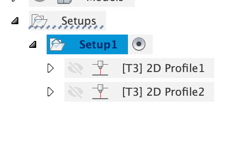
Probably already figured this out, but you can rename them from 2d Profile 1,2,3 etc…to Cut Small Holes, Cut Slots, Outer Profile or whatever you want to help keep up with them - especially when you have 3+ cut profiles. Can also reorder the operations them by click/hold/drag and moving up or down. Also, don’t cut the outside first…got to pay attention to the order of the cuts…AMHIK…
Also, you can use different cutting parameters (lead-in/lead-out values), type of cut (inside, outside or no offset), etc. on each profile as well. The other advantage of multiple profiles is they may generate individually where they won’t if you had them all in one.
Okay, I right-clicked on the profile but I can’t figure out how to rename it. I like that because like you said when the profiles start stacking up, it would be nice to know what’s what.
Thanks,
Anthony
Left single click to highlight/select it. Wait a second - then left single click (or double click) it again and it should go into edit mode where you can type the name out. You have to click on the text part, not the visibility eye or drill looking icon.
If you double click without highlighting first it will open the settings for that profile. They should add a field in the dialog for the name of the cut profile, but there’s not at present.
Thanks James, I got it now. Much appreciated.
Only Fusion360 could make such a task un-intuitive. 
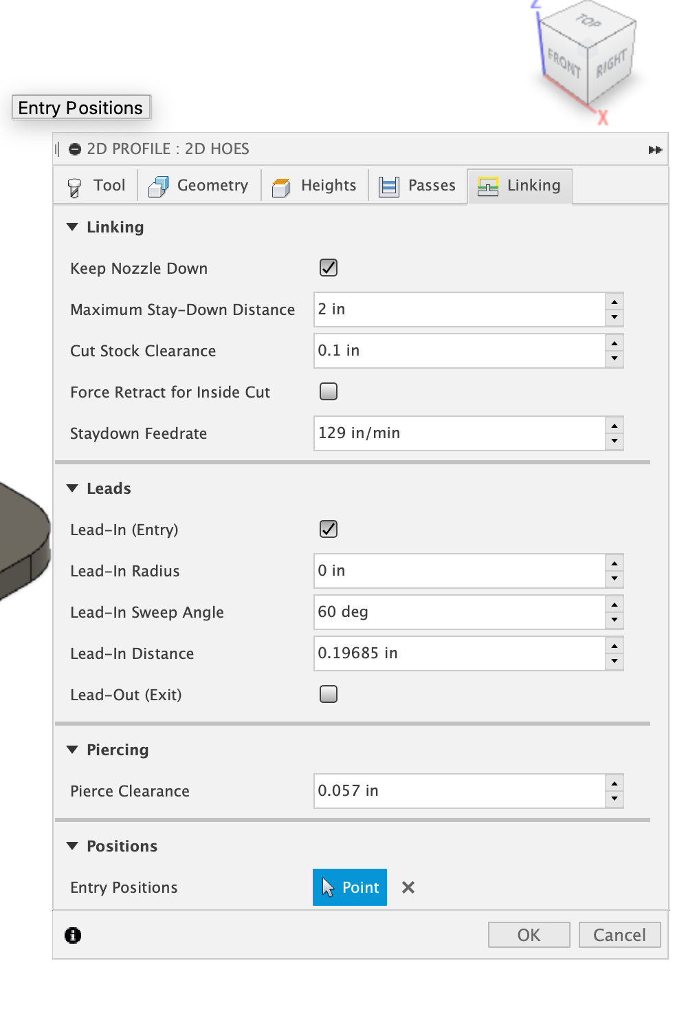
Okay so I have another question, since I only have the crossfire and have no Z axis control, I’m not quite sure on what all applies on this screen of the set up??!
More so on the leads section. Are all the lead settings only used if you have a Z axis control? When the info window pops up when I hover over each one it appears as if they are talking about piercing or something.Once again, thanks in advance to whoever can help out.
Anthony
Lead-in / out apply regardless of THC / Z axis. Those settings allow you to start your cut off the actual line you want to cut so the pierce does not affect your cut line and makes for a clean cut. There are times you don’t want lead in/out such as when you are cutting bend lines, and sometimes you want lead in and don’t care about lead out so much. I use lead in and no lead out on small holes for example, but there’s no real ‘rule’ on that - you just try to leverage them to make the best cut you can. All the other stuff on that tab I don’t touch and I have the THC. I think the post processor sets most of that anyway.
I don’t click keep nozzle down. I don’t set piercing here (set in post). Sometimes I use entry positions if I can see it put the entry in a place I don’t want, but usually it’s fine.
+1 level up for the 2d Hoes 
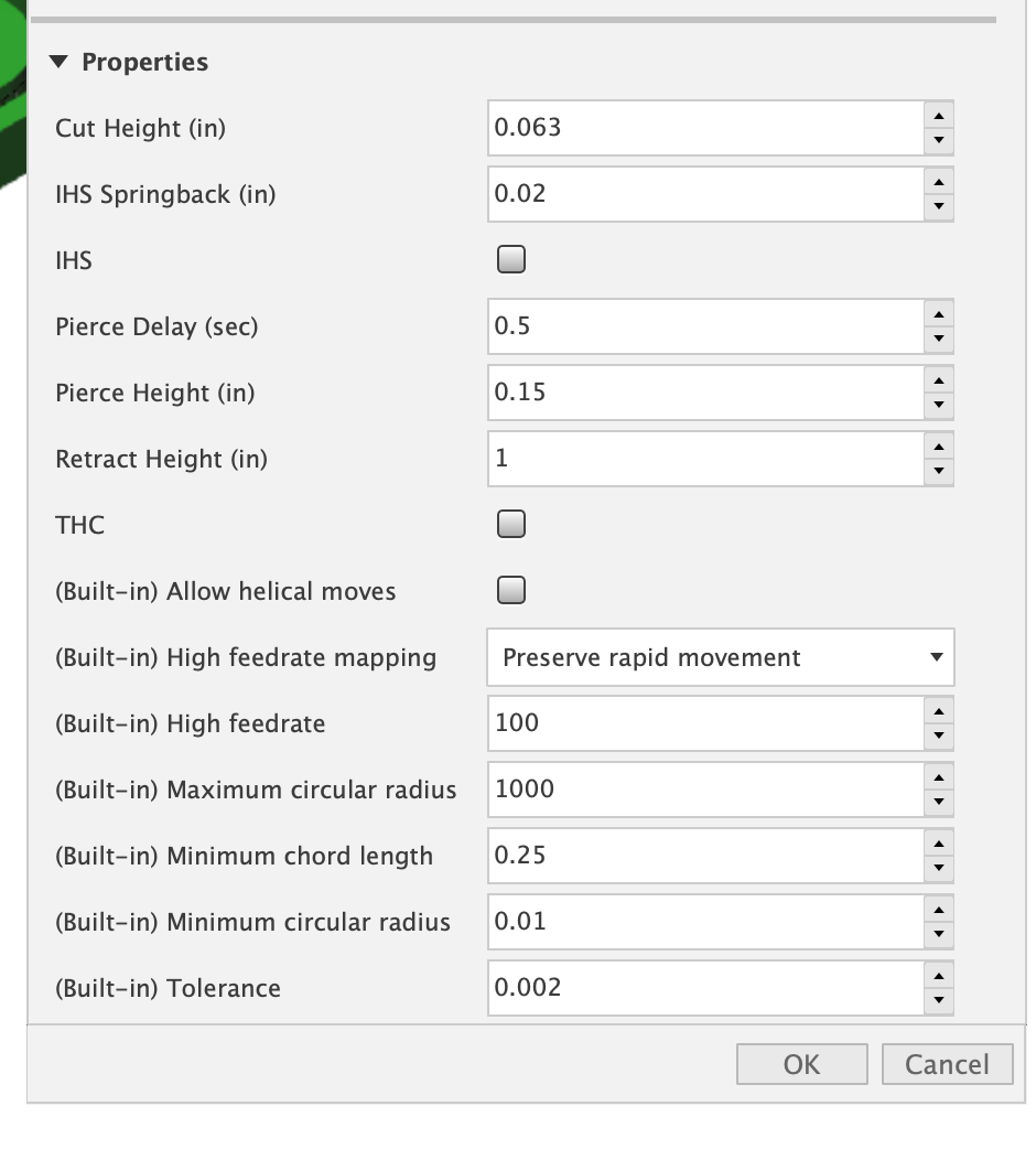
LOL I had to have a little fun renaming. When you mention "I don’t set piercing here (set in post) what does that mean? There’s still more setup after completing the tabs on this window? I usually do the “Setup” then the 2d Profile then click on the G1G2 and it creates the NC file. Nevermind I see there is a property drop down. I never really messed with that area before.
Is there anything I need to change in there even if I only have the Crossfire?Someone will have to check me on this, because you’re using Mach3 (I think) so the post process may be different, but there is a pierce height and delay setting when you ‘post’ or generate the gcode / nc file. It comes up in the window where you setup the post (file name, etc.) My understanding is the values set when you do this override all the settings in the 2d cut profile linking tab (except lead in /out).
Re-read question - yeah - that window you screen shot is what I’m talking about - those settings there override. Just leave THC unchecked (and IHS I think…)
In that screenshot - you are looking down on the cut - not from the side…
one step at a time…I’m still learning lots of stuff a year later…
Now that makes sense.
I’m using Firecontrol currently and I can’t wait for Langmuir Systems to come out with their z axis control upgrade for the crossfire table so I can go through the whole learning process all over again getting that dialed in ![]() …Thanks for the help James5.
…Thanks for the help James5.
Gotcha. I’m a little fuzzy on the non-pro versions. I had heard some are firecontrol, some are Mach3, but I don’t know the differences.
On the non pro just skip the whole properties section.
The pierce delay can be set for the whole job when you run the post processor to create the Gcode in Fusion before you send it to fire control.
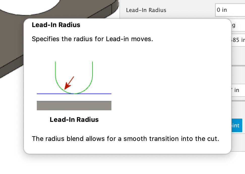
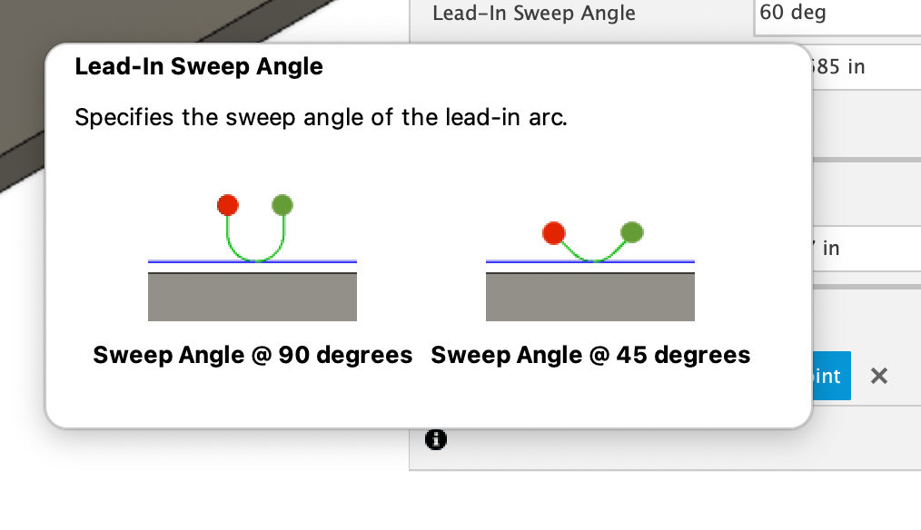
The lead-in radius I adjust depending on the part/profile I’m cutting. Some times for small holes I leave it out completely. For larger sweeping parts I might make it 30 or 60 degrees with a longer lead in that way I know I’m not going to get a blemish on the edge.
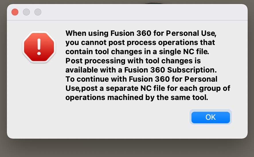
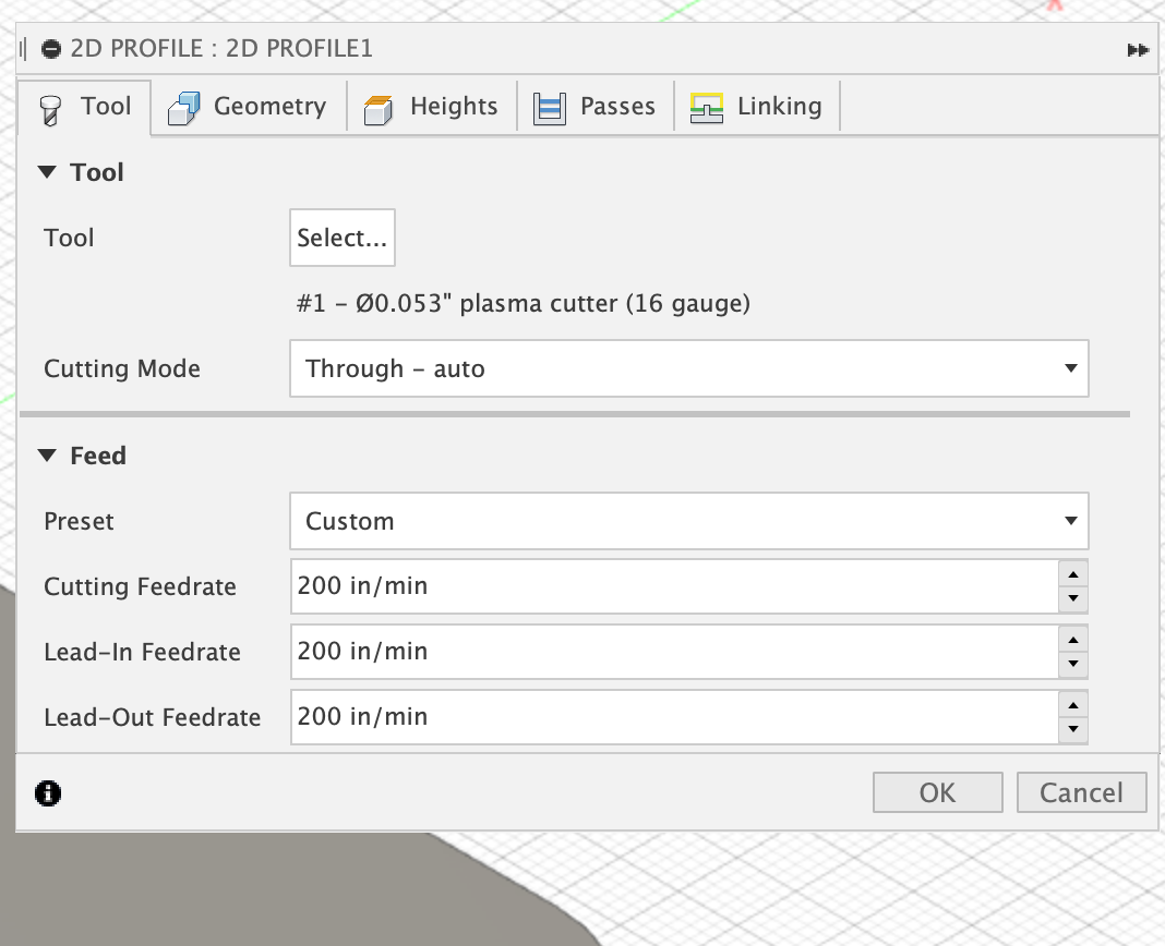
Thanks, Malebyr and James5, I have another question. Last night I was attempting to cut a simple 3x3 square out of some 18 gauge sheet. It has 4 1/4" holes that I was trying to see if it can make vs drilling them out. It seems to do well but on the first cut, it appears that it flies through the holes so fast that slowing down a tad would help. I have made two tool paths, one for the holes and one for the perimeter. The question I have is I was prompted with this message…
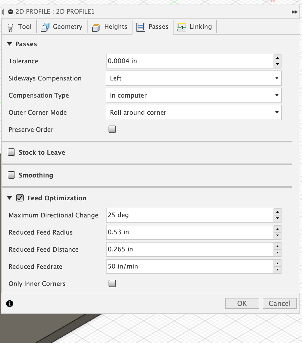
Is there a workaround for this? I had reduced the speed from 265 IPM to 200 just to see if the holes would come out better. I also tried feed optimization but I don’t really understand that part to well. When I attempted to do the feed optimization,(screenshot is just for reference, all other settings I left alone with the exception of the reduced feed rate. I bumped that up to 200 but I wasn’t noticing it slow down any, maybe I needed to mess with the other settings to get it to kick in?) nothing was changing, so I figured I’d change the whole speed altogether by creating a second tool path but that’s when I got the message.Thanks,
Anthony
Yes. Sheetcam ![]()
Not sure if this is part of F360’s recent personal use changes, but might want to try using same tool for both cut profiles - I see you are using tool #1 - make sure to use that on both. If it still does it, then it’s either upgrade or use something like sheetcam for the post. Note: sheetcam doesn’t do the design part - just the CAM part. You could also try making 2 seperate setups and creating a g-code file for the holes and a separate g-code for the outside profile and run them seperately- but that’s no fun. There may be another way I’m not thinking of…but that’s what it looks like to me.
Oh - and for small holes like that - I’ll drop down to 50 ipm depending on what’s being cut. The motors never really get up to speed on those small pieces, but they try when it’s set fast.
Okay James5, after posting my question I started researching and found a discussion where some other new user was experiencing the same issue. One guy said what you said and that was to make sure you’re using the same tool. I’ve since went back into that same part and deleted both profiles and started new. I put the same settings that I desired but made sure when it was time to select a tool that I selected it from the “setup” vs the standard library and that allowed me to create the gcode without any message warnings. I guess I just need to continue to learn this stuff. LOL at least I’m making progress, and eventually I can start making some $$$ on the side. Gotta nail this software though. Thank you for the speedy response
Here is the link to the discussion I was referring to https://forums.autodesk.com/t5/fusion-360-support/can-t-post-multiple-operations-that-all-use-the-same-tool/td-p/9781840 and a guy made a quick video explaining this as well. Video helped tremendously. I’m glad there are nice people out here on the forums helping out newbs like myself. Thank you all!
Anthony
I’m sorry I can’t help with the popup. I don’t get them so I can’t figure out a work around.
My fusion 360 is covered under my day job, so I don’t run into the personal limitations.
I do exactly what you were trying. Create a new tool for the holes that runs at a lower ipm (mmpm).
You can still do it with the personal you just have to create new gcode file for each tool.
So holes , then everything else.
Just make sure that your home point is the same for both files. I’ve wreaked Hours of work by not double checking my home was the same point on two different files. One was left hand bottom the other was center… Set the torch on the bottom left only to watch run to the middle of the (already cut sign) and fire the torch and slash it’s way trough the middle of everything as it cut the border faster than I could smack stop.
Been there and done that myself…![]()
![]()
Glad to hear!