Fusion 360 2020 for absolute newbies, Tips and tricks are welcome

Well… if you’re reading this then you are, or were, in the same boat as me. You bought the table and decided to try to learn autocad while waiting for it to be delivered. Maybe like me you looked at all the Langmuir videos… tried to replicate them but had errors come up, missing boxes, and generally got lost and overwhelmed and gave up. I know this because of tables Ive seen for sale with messages like"cant get AC360 selling my table".
Well… you arent alone and if it were not for a couple of very helpful forum members I might have given up too, as even the simplest of operations gave me fits and error codes. As a total newb I thought I would run this thread, chime in as I learn, and what is working for me in the simplest of fashion. The" I wish someone had told me that" evolution that might reduce your frustration.
First, you actually have to make the decision to learn autocad and not some of the others out there. I flailed around for a bit and then realized if I can learn one it will make learning the others much easier. For me it seemed like autocad with all its faults was still where I should focus my efforts. I spent about 20 hours messing around coming to this conclusion. Im merging my other posts into this one for brevity… thank you to those that have already helped me.

This will be an evolving thread as I learn Ill try to post what worked from start to one day cutting a part successfully. When I see all the work others have done Im heartened … if they can do it I can too. Im an experienced weldor and fabricator of 40 plus years. My passion is building unusual old medium duty trucks with modern technology. My table will be utilized to make parts for my projects.

This forum has people who are highly skilled at F360 and they may chime in, which is my hope.
Simple prerequisites… yes a computer with enough power to run autocad F360
(SPECS here
Autodesk shows these requirments
System requirements for Autodesk Fusion 360

WINDOWS BASED

Microsoft Windows Windows 10 (64-bit) Semi-Annual Release Channel
CPU Type x86-based 64-bit processor (e.g. Intel Core i, AMD Ryzen series), 4 cores, 1.7 GHz or greater; 32-bit not supported
ARM-based processors partially supported via Rosetta 2 only - see this post for more information.
Memory 4 GB of RAM (integrated graphics recommend 6 GB or more)
Graphics Card Supported for DirectX 11 or greater
Dedicated GPU with 1 GB or more of VRAM
Integrated graphics with 6 GB or more of RAM
Disk Space 3 GB of storage
Display Resolution 1366 x 768 (1920 x 1080 or greater at 100% scale strongly recommended)
Pointing Device HID-compliant mouse or trackpad, optional Wacom® tablet and 3Dconnexion SpaceMouse® support
Internet 2.5 Mbps or faster download; 500 Kbps or faster upload
Dependencies .NET Framework 4.5, SSL 3.0, TLS 1.2+

Recommended specs for complex modelling and processing
CPU Type 3 GHz or greater, 6 or more cores
Memory 8 GB RAM or greater
Graphics Dedicated GPU with 4 GB or more VRAM, DirectX 12 supported)

Im using an old desktop that barely runs the program and the choices out there are endless… if you have the money then put autocad 2020 best computers and up they’ll pop… looks like about 1200.00 gets you the hotrod computer… but members say they are successful with ones down in the 700.00 range… let your wallet be your guide

Ready set go…

a)Alright if you havent gathered all the Langmuir videos into your collection I suggest you do so… as well as fireshare… which I will experience at some point along with some of you in the future.

b) Download F360 2020 latest updated version… watch the Langmuir video if you dont know how to do it. There are many videos to show you how on the internet. While we are talking about videos remember… its just another person telling you what worked for them. I find a lot of 360 videos go way too fast and skip over many basic functions…Im a visual learner… show me each step and allow me to try it…
If you’ve downloaded current F360 you’ve already discovered that some of the “buttons” Langmuir refers to arent on your “homescreen”… fear not it will get better with a little practice and trying to get some F360 2020 videos… and yes they are popping up now… Ill list what I find

c) The first thing you’ll want to do is set your “preferences”… they are in the drop down menu under your name. (Gosh this gave me fits until I set them) Make sure you set your plane to x,y axis as the default. Set your units of measurement, in my case inches. Set any other preferences you want to your desired needs… and hit ok… and off to your first part.

d) Dont you wish we could all just jump to cutting?.. well… not just yet… we have to learn how to design a part first… SVG, DXF all these names are in foreign tongues… just like the commands made by technonerds in autocad…inkscape corel draw, a myriad of other software to learn… ugh… does it have to be so hard… well… not really… if you like start by importing a successful part (file) already drawn by someone else (Langmuir site has many helpful files already created …search the forum for them) into F360 just so you can get it from point A-Z without an error code. Inputting your machine …learning about a tool path… getting the file to manufacture… Langmuir instruction is good at that.

I suggest the below starter videos step by step to design a part from the beginning… note it is a 2020 version so you wont be hunting for non existent buttons or commands (which went into other areas after the November 2020 update). I will try to pick videos where the person speaks clear English, goes slow enough for most of us to understand and try to explain steps not just click through them.

Here’s a good one using INKSCAPE to capture an image and make it into an SVG file to bring into autocad… once you’ve mastered this then the world is your oyster as far as gathered images…

Now to beginning autocad… and designing a part. (This takes you through and into 3d… but all the concepts are the same…or so I believe)


From these two videos I learned how to draw lines, circles, arcs, how to set constraints for sizing and distance, and to extrude to 3d… that last part is not applicable to plasma cutting but was interesting. If you have to repeat these videos many times… don’t worry… I’m right there with you brother. Computers came about in my lifetime… and those of you who grew up on them then this is easy peasey. Me…I grew up on a measuring tape and a feel for design through experience.

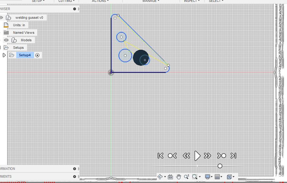
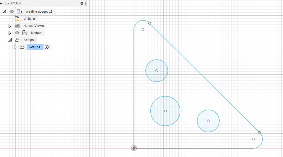
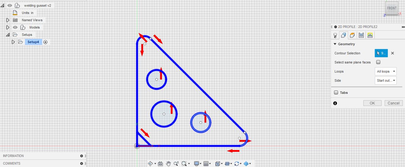
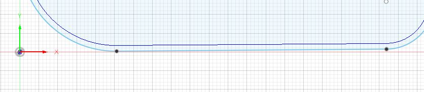
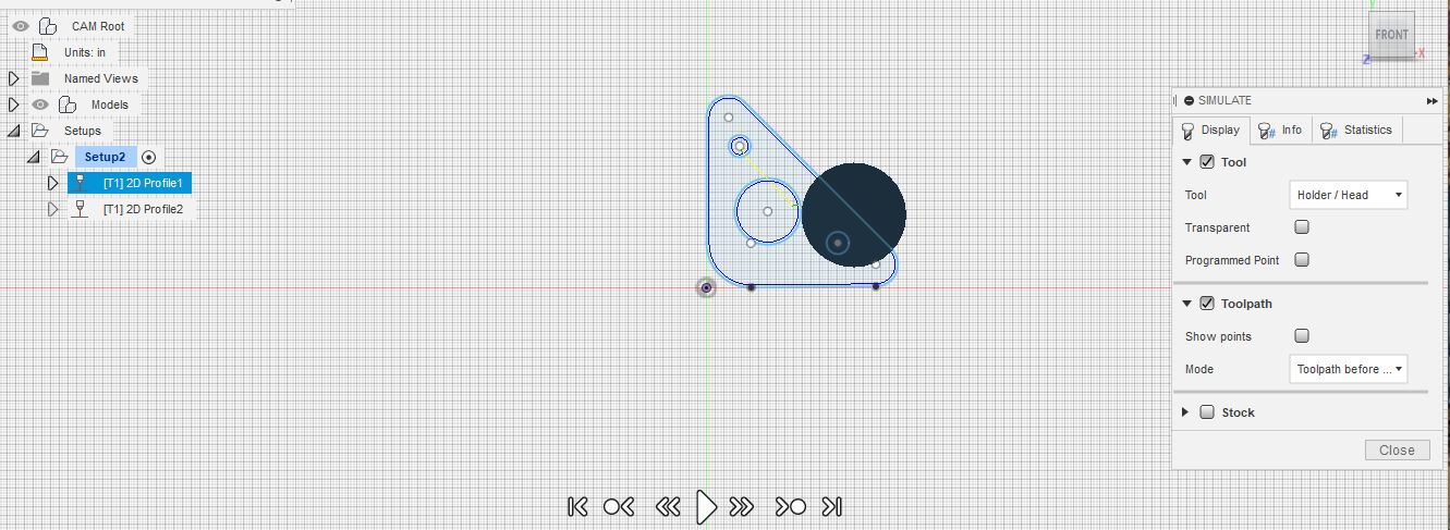
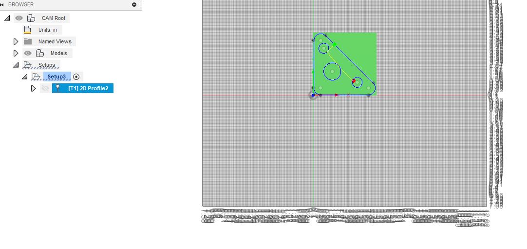
Now I can work on my basic welding gusset… with holes in it for hanging gear or just taking off weight and adding to the cool factor… Ill need to learn how to round the edges… next time

I suggest the KISS principle when first trying to design a part… for me just simple welding gussets will be fine (and there are already successful versions on the site).

That’s it for today… if you’re totally new like me and starting out you just got dog piled with information… come along with me on the journey of learning

7 Likes

Ten steps forward…20 back… or so it seems…
Welding gusset
As I stumble forward in frustration Langmuir makes its first delivery today
Worked on scale… I wanted close to 4 inches…( but I know there has to be an easier way to set line to exact lengths)
Worked on circles… had to line up everything manually… (but I know there has to be a way to snap everything into line)
Worked on radius corners… connecting everything… that took a number of tries… didnt get my 3 lines of the triangle points to connect… used pan and zoomed in to see they weren’t connected… and put them together manually (but I know there has to be a way to have them connect automatically to the radius)

Ah the joy of F360… I have to remember… several weeks ago I didnt know anything
When I went to manufacture and saw the tool path doesn’t look right and it isn’t smooth so I know Ive done something wrong (but no error code… just my looking at the simulation)

Why the squiggly lines outside my sketch?

That’s it for now until I get it successfully I wont post up a newby “this is how I did it” flow chart

What workspace are you working in?

That grid backgound grid doesn’t seem right … I usually leave the grid at default settings. For setting the sizes - I think the command you are looking for in ‘Dimension’ or D key shortcut. Dimension lets you set the size as you need it, but beware of constraints…a topic you’ll soon get into I’m sure…You can also set the size as you are creating a line or circle or rectangle…

Fortyfab-I had some of the attributes turned off, I closed the program and rebooted… this is what it looks like

James-Thank you for the “D” tip…Ill try that

I dont think the toolpath is correct because when I simulate it …it starts cutting the line on the right side of the triangle below the radius… then stops at the right bottom above the radius… then traverses back up the same line and then cuts all the rest including the radius and circles …

It seems to me the outside of the triangle should be cut in all one direction without traversing backwards? Am I wrong?
Also the x,y lines are in black and the rest are in blue…I dunno?

Also… I want to cut out the lower left of the triangle (so you dont weld into a corner)… havent figured that out yet.

Yeah your right all shapes should be cut continuously. It just looks like your original sketch isnt that great.
Something simple like a gusset is easy to make with just the simple sketch tools and it can be all done the size that you want.

If you start out making the triangle with the line command a box will pop up and you can just insert your measurement and left click your mouse and a new line will start from the end point then just do the same thing and the third line just follow up to the start and when you hover over the start point a small box will be around it click it and your triangle will be done and connected.
The circles if you have a certain spot you want them you can make a construction line to measure where you want to put them or atleast the first one if you want to make them in a line. After you make the first one if you hover over the center of the circle then move your mouse down a dotted blue line will follow to show you’re in the same center line of the first one.
I use construction lines a lot and circle patterns and constraints are your friend once you get the hang of them but they are confusing at first.
For the radius corners use the fillet command. if you hover in the corner after fillet is selcted click on it and another box will pop up and you can enter the radius that you want or use the arrow to push and pull the corner.
If you can do all that you will have a fully connected sketch. It just takes some time and practice to get used to the features.

1 Like

Thank you Sir, you have been really helpful and I do appreciate it

That fillet command will take care of that corner for you.

Also when you’re using the line command when you put in your measurement you can hit enter but you just have to use the shortcut key L or select the line icon again for every line.

1 Like

That was super helpful… and it was made very quickly… I have a linking constraint error… but I think I see what I did wrong…
Thank you

Constraint warnings will come up every once in a while normally there nothing to be worried about.
Like when you fillet a corner you will get a warning saying a dimension or constraint was changed during that operation.

Hot damn… I think I may have just made my first successful drawing… your help pulled me across the line… now …if I can just replicate it a number of times so it sinks in…

opps… not quite yet perhaps… in looking at my drawing blown up it appears some of the lines may be jagged… Ill look at that… but Im getting closer…hmm no error messages?..or as I like to say F360 “massages”

Today I dimpled die’d the drain holes in the water table…
Thats all the brain mush I can handle today…

1 Like

When you are doing your lines just make sure you are straight 90 that is if you want a straight line. You’ll notice there is 2 boxes open when you are making a line one for length and one for angle. You can either hit the tab key to go back and forth between the boxes or use your mouse to make the line go in whatever direction you want.
Your original picture your grid pattern was really small and your mouse will lock on to any junction in the grid so you could end up with something like 89.7 degrees instead of 90.

That jagged edge though in your last pic that is what it is because if it was straight the line would be following the x plane.

1 Like

I will be following this thread as I too am very new to any cad software and also trying to decide on which software is the most user friendly to begin with. I have Fusion360 currently and it seems nice but it also seems a little slow or glitchy at times. Nonetheless, I like your approach and look forward to seeing your progress.

Its going to depend on what kind of stuff you want to do with it. If you’re going to make a lot of dimensional stuff fusion is really good at that especially once you get the hang of using all the tools it has to offer. If you’re going to do mostly artsy stuff fusion probably isn’t going to be the best choice for cad even though it will do it its not the greatest.
Also with fusion you need to use it on a good computer or you will get bad lagging and crashing.
For me it works great because I do mostly all dimensional parts from scratch or reverse engineer existing parts plus I use it for 3d modeling to get parts 3d printed all in one program but I also have inkscape and sheetcam for the odd sign or design someone wants done.

4 Likes

Thanks for that information. What I plan to use my CNC table for is cutting plates for various builds on autos and motorcycles etc. mostly all two dimensional stuff. I have a new laptop arriving tomorrow fully spec’d out so it should be able to run whatever I throw at it thanks again for the info.

Fusion is great for that application. Once you get the 2d stuff figured out which is pretty easy with some practice it also does a whole lot more.
I build a lot of 4 link suspensions and with some quick measurements for frame rails and rear end you can model them in fusion and build every bracket for it and in the end you have a finished product that basically slides under the truck and bolts or welds in whichever way you decided to go.

1 Like

Exactly the types the things on my list that I would like to design. I’ve been practicing on fusion for a few weeks but after I design a particular plate with some holes, once I go try and simulate the cut, all the arrows indicating the travel direction throws me off. Like when you specify for the hole to be cut from the inside out, the arrows start to be placed all over the part and it gets confusing because they seem genetically placed near the hole and not really precise on their direction. So setting up the cutting route, offsets, figuring out speeds for cutting are all areas I need to work on. Then this whole “g-code” thing is next on the list, if that is something needed after getting everything else all set up. I have the month of January to continue practicing because my table should arrive by the beginning of February. So I’ll just keep at it I guess. Thanks for the info.

Anthony

There is definitely room for improvement with there direction arrows especially for smaller holes.
When you go through the 2d setup and hit ok it will show you the path with all the leadins and if any of them are wrong you can go to the drop down menu on the left and right click the profile and edit it and change the ones that are wrong by clicking on the arrow.

2 Likes

That’s exactly my issue with the smaller holes. I’ll give it a shot and report back when I have a chance after I set up my new laptop thanks again

40fab gets the new’b longevity tolerance award

Success

First file… they will get easier… I cant explain all the steps yet from a new’b perspective but Im at least making progress. I picked F360 because I was just wasting time looking a several softwares and I needed to buckle down and start somewhere. Ill continue to refer back to the “gusset” as I do edits… changes sizes, radius dimensions etc

Langmuir sent me a tracking number for the “second” shipment… looks like they will be several weeks behind their provided date… which all in all with covid and delays isnt bad at all.

If I can make a gusset then I can make a link… if I can make a link I can make shock towers, airbag mounts, steering box mounts… and on and on… I do plan on some sign work as well…

I still dont know why I get the squiggly lines in the bottom and side of my drawing… nor do I understand the small holes in the edges of the triangle…I didnt put them there… are they just reference marks in the program showing radii or an “operation” ?

This might sound really stupid… but what do I do with this file… does it load into fireshare… do I have to process it further in Fusion? How can I even transfer or access it outside of fusion?.. these are current questions Im asking myself
Let me see if I can find some direction for a search

Thank you

1 Like